How good are 'typical' cylinder heads from the factory?
Discussion


Just rechecked the specs on the rally engine above and the head was 29.5 not 30.5mm. The valvetrain was Schrick components whose cam profiles are not comparable with the profiles BMW use. The BMW Motorsport profiles have much faster valve acceleration and a much bigger price tag!
How does £800 per cam, £1000 a set of valves and another £1500 for springs and retainers grab you?
How does £800 per cam, £1000 a set of valves and another £1500 for springs and retainers grab you?
Edited by stevesingo on Monday 21st March 14:43
stevesingo said:
The s14 heads flow very well on the exhaust side to the point that the BMW Motorsport 29.5mm heads dont have any work done on the exhaust ports aside from the valve throat and seats are changed slightly.
As long as the exhaust ports are physically big enough, or can be made so, then all exhaust valves flow very well compared to inlets. The reason is simple. The shape of the inlet port is critical to direct the flow as evenly as possible all round the valve circumference to utilise the valve seat fully. An abrupt short side bend in an inlet port means the flow skips across the back of the valve and most of it exits into the chamber on one side of the seat. The valve circumference is therefore not being fully utilised in that case and the discharge coefficient suffers.On the exhaust side the flow has already passed through the valve seat so the shape of the port after that is much less important. It obviously isn't ideal for it to bend too abruptly but it really doesn't matter too much. What matters for good exhaust valve flow is that the exhaust valve seat isn't shrouded inside the combustion chamber and provided that's achieved then the valve seat will flow at peak efficiency round all of its circumference, something you can almost never achieve with an inlet valve.
That's why if you look at your cut-away heads the inlets are very downdraft and machined as straight as possible and the exhausts are not as it simply isn't necessary. I don't even bother flow testing exhaust ports and never have. You can tell all you really need to from the port size and the ratio of that to the valve size. I like to machine out to a minimum port diameter of 80% of the valve diameter, ideally a bit more and it does depend on the state of tune, remove any particularly nasty bends and changes of shape and that's pretty much all you need to do to guarantee a discharge coefficient higher than that of even the best inlet ports.
stevesingo said:
Inlets 38.5 exhaust 32.5 followers 37.5.
Cam base circle is 33.5 and valve lift is 11.75
Wow those are big followers for a 16v engine. Why so little valve lift then I wonder? Cam follower diameter directly affects the lift you can achieve from a given cam duration. You could be up around, or even over 13mm lift with your cam durations on a follower that size. Some free power going begging there methinks. I've just designed some nice tractable 290 degree seat duration cams for a 2v engine with 38mm followers and 12.5mm lift was nowhere near pushing the limits but the max lift was determined by valve spring clearance without going to silly special springs at more expense. Anyhoo.Cam base circle is 33.5 and valve lift is 11.75
Ratio of exhaust to inlet valve diameter is really nothing out of the ordinary for a 4v engine at 84%. I'd still suggest exhaust cam duration closer to that of the inlet would be better.
Running those valve sizes, estimated port flow efficiencies and various other things through the power prediction programme I start each engine design off with I'd like to expect a lot closer to 300 bhp and 215/220 ft lbs from an engine in your spec than 270 bhp, even with fairly mild tractable cams.
I did a 1600cc 4v Peugeot a while back with cams of about 245 degrees at 1mm lift (that's maybe 280 degree seat), big valves, throttle bodies etc and that made low 190s bhp so about 120 bhp per litre, 90 ft lbs per litre and a power band from 3k to over 9k. With more cam it made well over 200 bhp but needed to be a daily driver so I opted for a nice tractable compromise.
Pro rata that's exactly 300 bhp from yours. OK your big bore cylinders won't burn quite so well as 79mm ones but I'd be deeply unhappy with less than 290 bhp and 215 ft lbs.
Seems like I'll have to have a tinker with some BMW engines one day and see what can be done

stevesingo said:
Just rechecked the specs on the rally engine above and the head was 29.5 not 30.5mm. The valvetrain was Schrick components whose cam profiles are not comparable with the profiles BMW use. The BMW Motorsport profiles have much faster valve acceleration and a much bigger price tag!
How does £800 per cam, £1000 a set of valves and another £1500 for springs and retainers grab you?
F**ks sake. I could design and make the lot even as a one off for a fraction of that. I did a set of big inlet valves for a 5v per cylinder V6 Audi rally engine once. Nasty bloody fiddly little things with 5mm valve stems and 28.4mm heads. Even with the design cost and making a one off set of 18 it was under £300. Springs are easy, there's always something from another engine that'll do the job once I've calculated the stresses and loadings I need. Retainers my mate can knock out on his CNC lathe from steel or titanium. I design my own cams anyway as long as blanks are available or one offs can be done from EN40B billet. Someone out there is making serious money it seems but it sure as hell isn't me.How does £800 per cam, £1000 a set of valves and another £1500 for springs and retainers grab you?
Here is a cam profile graphs for the some cams
Schrick 276, 284, 292 and BMW MS 312 inlet cam
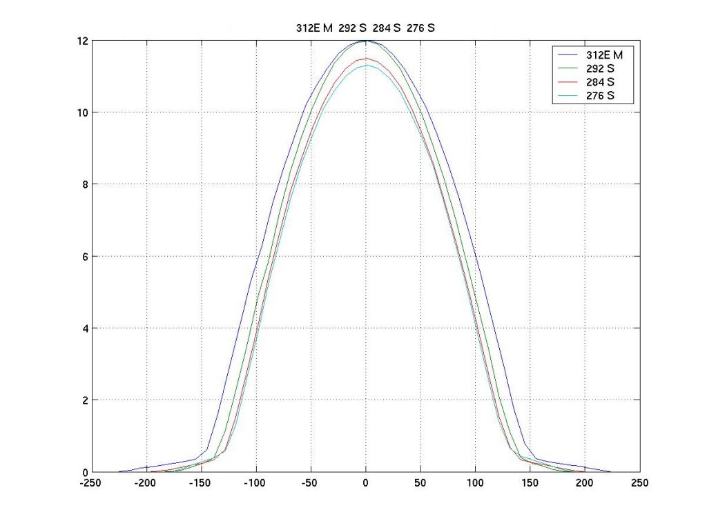
It looks like my 292 had 265deg @ 1mm lift
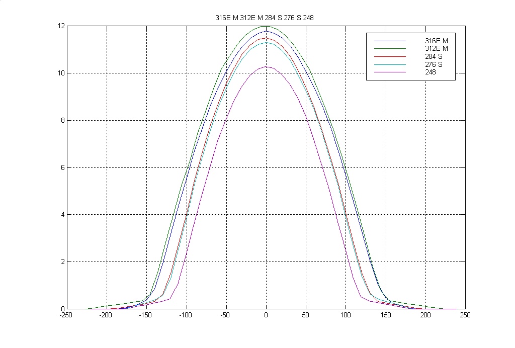
BMW MS 316, 312 inlet cams, schrick 284,276 and a stock inlet/exhaust cam from an early 26mm inlet engine (200hp)
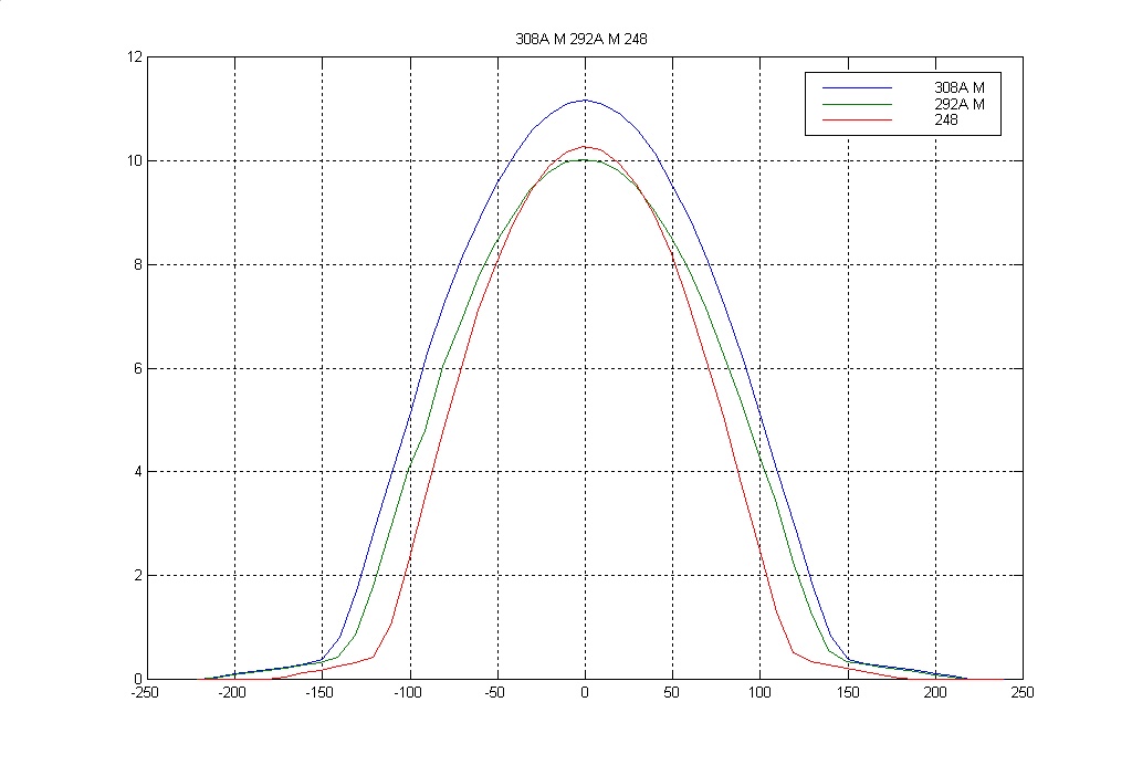
BMW MS 308, 292 exhaust cams and anothe stock cam
One of the issues with the higher lift cams is the there is limited space in the cam box. I had to modify my cambox for my inlet cam clearance. Also in order to avoid becoming coil bound, the BMW MS valves are longer with the collet grooves higher up the stem. This pushes the follower further up the follower bore therefor presumably reducing the stability of the follower.
A pic of the intalled engine with the DTM intake!

Thanks for your input. 290hp would be nice.
Sorry for hijacking the OP's thread.
Schrick 276, 284, 292 and BMW MS 312 inlet cam
It looks like my 292 had 265deg @ 1mm lift
BMW MS 316, 312 inlet cams, schrick 284,276 and a stock inlet/exhaust cam from an early 26mm inlet engine (200hp)
BMW MS 308, 292 exhaust cams and anothe stock cam
One of the issues with the higher lift cams is the there is limited space in the cam box. I had to modify my cambox for my inlet cam clearance. Also in order to avoid becoming coil bound, the BMW MS valves are longer with the collet grooves higher up the stem. This pushes the follower further up the follower bore therefor presumably reducing the stability of the follower.
A pic of the intalled engine with the DTM intake!
Thanks for your input. 290hp would be nice.
Sorry for hijacking the OP's thread.
Edited by stevesingo on Monday 21st March 15:02
stevesingo said:
It looks like my 292 had 265deg @ 1mm lift
That needs to be 1mm plus clearance to get actual valve lift i.e. about 1.2mm to 1.25mm at the cam so I suspect it's less duration than that. Remember the cam has to take up the valve clearance before any actual valve lift takes place. Trying to take a measure off the graph I get about 255 degrees at 1.25mm but the scale is a bit small to be precise.That's not too radical and should be ok above about 3.5 to 4k rpm. Much more duration than that and things get a bit unpleasant at low rpm with big valve 4v motors though.
The 276 and 284 make my point nicely that seat durations are immaterial given they both have almost the same profile but very different quoted figures. The 1mm + CL duration can very easily be the same on cams with 10 or more degrees difference at the seat if one of them lifts off the seat slowly.
Pumaracing said:
That needs to be 1mm plus clearance to get actual valve lift i.e. about 1.2mm to 1.25mm at the cam so I suspect it's less duration than that. Remember the cam has to take up the valve clearance before any actual valve lift takes place. Trying to take a measure off the graph I get about 255 degrees at 1.25mm but the scale is a bit small to be precise.
That's not too radical and should be ok above about 3.5 to 4k rpm. Much more duration than that and things get a bit unpleasant at low rpm with big valve 4v motors though.
The 276 and 284 make my point nicely that seat durations are immaterial given they both have almost the same profile but very different quoted figures. The 1mm + CL duration can very easily be the same on cams with 10 or more degrees difference at the seat if one of them lifts off the seat slowly.
Pumpa, is it best to open the valves fast and close slow, open fast and close fast or open slow and close slow? I read thatthere was a alot of performance to be had on the EVOS by using piper 272 cams as opsised to HLS ones. I think i read that the duration @ +1mm was much more on the Pipers. i guessthat menas they where letting the heads flow better? That's not too radical and should be ok above about 3.5 to 4k rpm. Much more duration than that and things get a bit unpleasant at low rpm with big valve 4v motors though.
The 276 and 284 make my point nicely that seat durations are immaterial given they both have almost the same profile but very different quoted figures. The 1mm + CL duration can very easily be the same on cams with 10 or more degrees difference at the seat if one of them lifts off the seat slowly.
Thanks,
Chris.
Open fast, close fast! Thats why you need big lifter diameter, so you can have high valve accelerations without getting into horrible high contact pressures that are a result of geometery compromises from small lifter diameter etc!
The opening and closing "ramps" and the blend between those and the main "profile" are critical for controlling the valve dynamics, which has an impact on everything from noise to wear.
If you plot out the accelerations from your valve lift curves, you will soon find that unless you have lift data to 3 or 4 significant places the acceleration of the acceleration looks hideous! (and often, on poor cams, is.........)
Pumaracing, have you ever experimented with surface finishes in the ports to see if this has any effect on performance or cylinder head temperatures?
The reason I ask is that when tuning piston-ported two stroke bikes back in the 70's and 80's there always seemed to be two schools of thought.
One maintained that surface finish was unimportant, the odd tool mark didn't matter and that size and shape were paramount.
The other was train of thought was that surface finish was vital ie polished to a mirror smooth surface, otherwise no matter what was done with the size and shape of the ports the engine would not work as efficiently.
Max_Torque said:
Open fast, close fast! Thats why you need big lifter diameter, so you can have high valve accelerations without getting into horrible high contact pressures that are a result of geometery compromises from small lifter diameter etc!
Actually what the lifter diameter primarily limits is not acceleration (which I agree it does due to lower contact pressures) but the maximum velocity i.e. maximum opening rate in thou per degree. As the cam lobe wipes across the follower it's the opening velocity that determines how far from from the centreline of the cam the contact point between the lobe and follower sits. The contact point obviously has to stay inside the circumference of the lifter. If the lobe runs off the edge of the follower then everything breaks in very short order.A cam lobe has 4 phases.
1) Opening ramp to take up the valve clearance. This is a very short ramp on a hydraulic lifter cam profile which is theoretically always in contact with its follower which is why hydraulic profile cams can't be used with solid lifters but vice versa is ok. It's very clear from the graphs above that these are all solid lifter cams from the 70 or so crank degree opening ramps to take up the valve clearance. A hydraulic cam profile would have opening ramps a fraction of that duration.
2) Acceleration phase where the velocity builds up to its peak.
3) Constant velocity phase where the cam opens at the same maximum rate and the cam profile curve is a straight line.
4) Deceleration phase as the opening velocity slows back down until it's zero at full lift.
Where R = Radius of follower in thou the maximum follower opening velocity in thou per degree of crankshaft duration is given by the equation (R-25)/114.6
Only at zero lift and full lift, when at both times the velocity is zero, is the contact point directly under the centreline of the cam. As the cam opens and the velocity builds up the contact patch moves away from centre, reaches its maximum lateral displacement at peak velocity and then moves back to centre as the valve slows down to reach peak lift and then it all repeats on the closing side.
With a larger diameter follower the acceleration phase can be extended to build up to a higher velocity which means more lift from a given duration in more or less direct proportion to the follower diameter.
This is why engines with pushrods and rockers can use smaller diameter lifters and direct acting overhead cams must use larger ones as there is no rocker multiplication ratio to increase the maximum lift from a given cam duration.
It should therefore be apparent that the effective follower diameter of a pushrod engine is rocker ratio x follower diameter when making comparisons with a direct acting OHC engine.
Edited by Pumaracing on Saturday 26th March 10:29
Edited by Pumaracing on Saturday 26th March 20:09
Tango13 said:
Pumaracing, have you ever experimented with surface finishes in the ports to see if this has any effect on performance or cylinder head temperatures?
Port finish is almost completely immaterial. It has little effect on flow and that has been tested to death over the decades so I'm surprised there would still be any debate about it. It is generally accepted that a slightly rough finish (i.e. a bit less than shiny) on inlet ports helps prevent fuel particle dropout from the air fuel mixture clinging to the port walls. Exhaust ports don't care one way or the other as the fuel is already burned by then.A rough cast port flows just the same as a CNC machined shiny one with the same average dimensions so all the spit and polish most head porters put on their work is purely to satisfy punters who think shine = power.
This is perhaps why the common phrase "port and polish" sets my bleedin' hackles on edge as the polish bit is mainly detrimental and most of the tosspots out there who think they can build engines have no clue what the correct basic shape should be anyway.
stevesingo said:
The valvetrain was Schrick components whose cam profiles are not comparable with the profiles BMW use. The BMW Motorsport profiles have much faster valve acceleration.
Looking at the graphs you have posted it's very clear that this is not the case.Referring to my previous post the 4 phases of the cam lobe can be clearly seen in your graphs.
1) The opening and closing ramps are the straight line constant velocity sections at the start and end of each curve. They take up the valve clearance gently so as not to smash the cam lobe into the lifter at the start or the valve onto the seat at the closing end. About 70 degrees of crank rotation is needed just to increase or decrease lift by 0.4mm which adequately covers the 0.2mm to 0.35mm clearance range that most OHC engines use.
2) The acceleration phase is very brief, only about 20 crank degrees which you can see where the graphs curve round rapidly to get into the constant velocity phase.
3) The CV phase is the straight line section before the graph starts to curve round again towards peak lift in the deceleration phase. Put a ruler against any of the lines on your graphs and you can see where this section extends to and from. As I said above the maximum opening or closing velocity is limited by the cam follower diameter and you can see very clearly that the CV phases on all of those cams have about the same slope i.e. the graph lines are parallel for all of the cams in that region so they all use the same maximum velocity. In fact the stock cam in the second graph has the fastest opening rate of any cam shown which you can see from the slightly steeper curve.
The BMW Motorsport cams clearly don't open any faster than the Shrick or stock cams. The stock cams also have slightly more aggressive opening ramps which given they presumably have an adequate service life means the performance cams are probably not really pushing the envelope.
All the BMW Motorsport cams have is more duration and frankly don't use that to the full to generate the lift they otherwise could have which could of course be proportionately more than the lift of lower duration cams. Nothing special is apparent in their graph profiles at all. In fact the Shrick cams generate more lift from a given duration than the BMW ones.
BMW is charging money for old rope matey. Any cam with a given duration and given lift will have almost identical performance in the engine because there simply isn't anything special anyone can do to exceed the limits dictated by follower diameter and the maximum allowable contact stresses.
All that ever varies is the advertising puffery trying to convince punters that company X's cams are special in some way. They never are.
Edited by Pumaracing on Saturday 26th March 10:21
Thread resurrection time with a question for Pumaracing Dave...

Those are SAE flywheel figures. 214hp@wheels.
I think the ramp rate was a little high at 500rpm/sec, but I don't think that would account for 40 odd hp.
56lb/min 590cc/min injectors
66% duty at Peak power
gives a BSFC of 0.635lb/hp Which is way outside the normal boundarys for a NA engine.
The engine has a large cylinder surface area and therefore I don't expect it to be very efficient.
Doing a little reverse maths from inj pulse width, duty cycle and estimated BSFC...
BSFC @ 0.60lb/hp = 270hp
BSFC @ 0.55lb/hp = 292hp
BSFC @ 0.50lb/hp = 325hp
I think I can safely discount the last one, as that is way more than similar engine builds have made.
270-292 seem a a little more reasonable in the 0.55-0.60lb/hp region.
Could I ask Dave what he thinks?
Many Thanks.
stevesingo said:
I have a 29.5mm head on my 2.5, 292 (265@1mm) inlet 284 exhaust 11.9:1 compression. Intake system and exhaust are good. I'm expecting 270bhp and about 200lb/ft. Is this reasonable? Bore is 95mm, stroke 87mm and the cams are timed at 102 on the inlet and 106 exhaust.
Pumaracing said:
Pro rata that's exactly 300 bhp from yours. OK your big bore cylinders won't burn quite so well as 79mm ones but I'd be deeply unhappy with less than 290 bhp and 215 ft lbs.
stevesingo said:
We will see in a month or so when I tune it on the rollers.
Steve
Not quite a month as I got alittle tied up with work, moving house blah blah...Steve
Those are SAE flywheel figures. 214hp@wheels.
I think the ramp rate was a little high at 500rpm/sec, but I don't think that would account for 40 odd hp.
56lb/min 590cc/min injectors
66% duty at Peak power
gives a BSFC of 0.635lb/hp Which is way outside the normal boundarys for a NA engine.
The engine has a large cylinder surface area and therefore I don't expect it to be very efficient.
Doing a little reverse maths from inj pulse width, duty cycle and estimated BSFC...
BSFC @ 0.60lb/hp = 270hp
BSFC @ 0.55lb/hp = 292hp
BSFC @ 0.50lb/hp = 325hp
I think I can safely discount the last one, as that is way more than similar engine builds have made.
270-292 seem a a little more reasonable in the 0.55-0.60lb/hp region.
Could I ask Dave what he thinks?
Many Thanks.
Surely AFR will affect the BSFC, did you vary AFR to find the optimal number.
There is no AFR shown. Also of course varying spark to find MBT is also required.
Just chucking a nicely built engine on the dyno and hoping to hit perfect numbers without running at LBT and MBT in is a recipe for disappointment.
(ie) Maybe your missing power in the tune side of things.
There is no AFR shown. Also of course varying spark to find MBT is also required.
Just chucking a nicely built engine on the dyno and hoping to hit perfect numbers without running at LBT and MBT in is a recipe for disappointment.
(ie) Maybe your missing power in the tune side of things.

ringram said:
Surely AFR will affect the BSFC, did you vary AFR to find the optimal number.
There is no AFR shown. Also of course varying spark to find MBT is also required.
Just chucking a nicely built engine on the dyno and hoping to hit perfect numbers without running at LBT and MBT in is a recipe for disappointment.
(ie) Maybe your missing power in the tune side of things.
Forgot to add...There is no AFR shown. Also of course varying spark to find MBT is also required.
Just chucking a nicely built engine on the dyno and hoping to hit perfect numbers without running at LBT and MBT in is a recipe for disappointment.
(ie) Maybe your missing power in the tune side of things.
It made this power at Lambda 0.89. It made a little more (1-2hp which may be in the dyno repeatability) at 0.90, but not worth the risk of inflated temps.
That was at MBT. In steps of 2 deg we gained until we got to +6deg of the base. At +8deg we gained no more and no knock either.
The only thing I might be missing is in inj timing, but at these rpm, I doubt it will make much difference.
HTH
Steve
Gassing Station | Engines & Drivetrain | Top of Page | What's New | My Stuff