Nearly pointless filter tinkering
Discussion


OK, I cant sleep so I thought i'd post
I cannot afford to insure any mods on my car yet, naturally I'm using the time to design things in my head and come up with ideas.
There is very little you can do to a 4a-ge without rebuilding it. Rebuilding one is not cost effective when you can just swap it out with a 4a-gze or a 3a-gte for the same price. The one flaw the engine does have in a Mk1 MR2 is the really odd air intake.
The stock air intake comes from the throttle body, through a hard pipe to the air mass metre in the bottom o/s corner of the engine bay, it then turns a corner and passes into the boot to the air filter box. The air is then ducted through restrictive piping all the way around the outside of the boot, under the light clusters, around under the radio antenna to the scoop on the n/s.
What some people have done is replace this arrangement with a good quality cone filter in the boot and ducted a cold feed to the top of the boot. I think this is unsightly and would have problems with rain getting in if not correctly done. You can get a dyno proven 4-5 bhp doing this however.
The best place for the filter would be directly behind the n/s scoop in the engine bay, the problem is the air mass metre is hard to move and ducts into the boot. A method would have to be devised to get the air from the filter.
One way would be to take a flexible pipe, and make a sweeping 180 degree curve from the boot back into the bay, passing back under the mass metre and around to the filter. The problem with this lies in that newton's laws, simply put, state that making the air turn a corner will slow it down and cause drag. This can be reduced by using large bore pipes to a degree.
A variation on this is to put the cone filter in the boot, inside a fabricated air box which is then ducted freely to the intake. There are logistical problems with this and would sacrifice boot space.
A more adventurous idea would be to disconnect the assembly from the throttle body, and move the whole thing to the other side of the engine. This would then be followed by ducting the air to the throttle body and extending the wiring loom to the relocated sensors. This would require massive effort and possibly a weight deficit considering the additional fabricated supports for the assembly. This is complecated by the simple fact it might not work and screws up the car.
Has anyone tried to do a similar thing to one of these cars? Any better ideas?
p.s. yeah i know, spending out for a measly 5bhp, I shouldnt do it
AFAIK it only needs an ECU reset. Mass metre picks up extra air and adjusts. Problem is there isnt much documentation or proven info out there thanks to Mr Barry. I swear I saw someone who'd gutted the air mass metre, choke, everything after the throttle body and stuck a filter directly on the throttle body. Not only is he drawing warm air in from the engine bay but I dont know how he hasnt put a piston through the block without the air mass sensor
edited to add
kwality! Not the same picture as I saw the last time but another muppet! The page referrs to the air mass metre box as the "resonator box" and should be removed, along with all sensors. Also using K&N filter which bench tests results have shown is the least efficient aftermarket filter of all popular brands
Sauce = www.fourwheels.org/mr2/knfilter.shtml
>> Edited by sadako on Thursday 24th February 08:12
Hi,most air filter mods,for MR2's that I've seen have just replaced original box for a decent cone filter.I can't imagine(& never heard of)any probs with rain water entering,as its under the cowl arch.Also its right next to the air intake boot panel/fans sucking warm air(esp when moving)oughtn't to be too much of a problem.
My own experience of adding cold air feeds is;keep it simple,use widest bore pipe you can fit & keep that pipe work as straight as possible.It's not really worth going mad over as gains are negligable.I've seen ppl add the air ram/scoop thingies to MR2s',imho-they're pretty ugly tho.
Heres a pretty heinous example of an abused MR2.sorry,but its the only pic showing the air scoops I have.
Yes, its in the golf club compartment between the engine bay and the rear bumper. On the pic I posted the car is pre revision, having the filter box beside the battery. On a post revision the pipework goes the other way, through the bulkhead into the side of the boot. I dont have the slightest idea why they changed this with the engine revision however

I'm working out how the thing works as I go along. It should work considerin the odd way the choke works (thermostat valve bypasses the throttle body, MAP sensor picks up airflow, adds more fuel, revs increase)
Hoping someone is going to turn up who is a veritable oracle on the subject. I'm not the kind for visual mods but I'd like to try things that may give me a bit more go that a novice can install, in the future of course...
Hoping someone is going to turn up who is a veritable oracle on the subject. I'm not the kind for visual mods but I'd like to try things that may give me a bit more go that a novice can install, in the future of course...
sadako said:
OK, I cant sleep so I thought i'd post
I cannot afford to insure any mods on my car yet, naturally I'm using the time to design things in my head and come up with ideas.
There is very little you can do to a 4a-ge without rebuilding it. Rebuilding one is not cost effective when you can just swap it out with a 4a-gze or a 3a-gte for the same price. The one flaw the engine does have in a Mk1 MR2 is the really odd air intake.
The stock air intake comes from the throttle body, through a hard pipe to the air mass metre in the bottom o/s corner of the engine bay, it then turns a corner and passes into the boot to the air filter box. The air is then ducted through restrictive piping all the way around the outside of the boot, under the light clusters, around under the radio antenna to the scoop on the n/s.
What some people have done is replace this arrangement with a good quality cone filter in the boot and ducted a cold feed to the top of the boot. I think this is unsightly and would have problems with rain getting in if not correctly done. You can get a dyno proven 4-5 bhp doing this however.
The best place for the filter would be directly behind the n/s scoop in the engine bay, the problem is the air mass metre is hard to move and ducts into the boot. A method would have to be devised to get the air from the filter.
One way would be to take a flexible pipe, and make a sweeping 180 degree curve from the boot back into the bay, passing back under the mass metre and around to the filter. The problem with this lies in that newton's laws, simply put, state that making the air turn a corner will slow it down and cause drag. This can be reduced by using large bore pipes to a degree.
A variation on this is to put the cone filter in the boot, inside a fabricated air box which is then ducted freely to the intake. There are logistical problems with this and would sacrifice boot space.
A more adventurous idea would be to disconnect the assembly from the throttle body, and move the whole thing to the other side of the engine. This would then be followed by ducting the air to the throttle body and extending the wiring loom to the relocated sensors. This would require massive effort and possibly a weight deficit considering the additional fabricated supports for the assembly. This is complecated by the simple fact it might not work and screws up the car.
Has anyone tried to do a similar thing to one of these cars? Any better ideas?
p.s. yeah i know, spending out for a measly 5bhp, I shouldnt do it
Hi Sadako,
I've also been thinking about the air-intake on my MK1b. However, I'm still rebuilding the bodywork so I haven't actually got round to looking at the system in detail. Are you certain that the big box is the AFM as I too have seen pictures of the air filter mounted directly onto the throttle body eg. http://homepage.ntlworld.com/nick.challoner/mr2/tech/jr.html
I'm not saying you're wrong, rather I'm surprised for example if the guy above has got it wrong.
Btw, I think you have your o/s and n/s mixed up.

That link has a mk1a as far as I can tell. His filter box is where my MAP is, assuming thats what it is. I've seen a lot of things saying "dont take this box apart, undoing the screws fscks it up.
From what i know of the engine some use AFMs some use MAPs, I think different revisions may have different sensors.
What bodywork are you doing BTW, Wheel arches?
From what i know of the engine some use AFMs some use MAPs, I think different revisions may have different sensors.
What bodywork are you doing BTW, Wheel arches?
sadako said:
That link has a mk1a as far as I can tell. His filter box is where my MAP is, assuming thats what it is. I've seen a lot of things saying "dont take this box apart, undoing the screws fscks it up.
From what i know of the engine some use AFMs some use MAPs, I think different revisions may have different sensors.
What bodywork are you doing BTW, Wheel arches?
Hi yes that's a MK1a. Mine's a MK1b (1987) so when you decide the best air filter solution please post to say

Bodywork I'm working my way back. I'm replacing the front bumper-bar and wings. While I'm in there I'm replacing the radiator which as usual has lost most of its fins.
Next I'm welding some small holes in the A-posts and then the sills.
I'm leaving the rear arches until last. They aren't as bad as the previous MK1 I owned, so for the moment I may just fill them with fibre-glass. My main aim at present is to have the car looking good and not be degrading any further.
I've also got a Mongoose to fit and some nice gold alloys (Mica blue car).
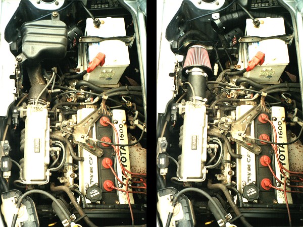
The engine in the photos has no air flow meter so it must be a MAP based system using a manifold absolute pressure sensor.
Toyta's system is the Tccs and uses two different types that i know of.
One is the air flapper type of air flow meter and the other is Map...which is what you have.
Toyta's system is the Tccs and uses two different types that i know of.
One is the air flapper type of air flow meter and the other is Map...which is what you have.
I have a red one. There is a little bondo in places but its in mostly good shape. The rust started coming through the wheel arches this winter and spreading fast. Nothing I can do about it till summer though. Went out to install the glass mounted DAB antenna and nearly froze my hands off. I'll be bedding cables and installing 3rd brake light during the summer time too
sadako said:
I have a red one. There is a little bondo in places but its in mostly good shape. The rust started coming through the wheel arches this winter and spreading fast. Nothing I can do about it till summer though. Went out to install the glass mounted DAB antenna and nearly froze my hands off. I'll be bedding cables and installing 3rd brake light during the summer time too
My last one was red. The advantage was that it was easy to blend in touch-up paint, the disadvantage is that the red can fade to pink

I assume you are aware that around the lip of the rear arches, between outer and inner wings, there is a strip of foam. This soaks up water and rots the arches from the inside. If corrosion has reached the surface then
 arches . I welded in arch repair panels to my previous MR2 but avoiding heat distortion is very difficult hence my thoughts of using fibreglass this time. I'm not fully decided on this though.
 PS There's loads of useful info here:
www.mr2mk1club.com/repairsindex.html
Including
www.mr2mk1club.com/repairsp46.html

Yes but I cant weld, and I cant afford to get them replaced. If they are gone from the inside i'll just have to grind off all the rust/dead arch and use hammerite to stop it spreading. It should keep the rest of the panel in one piece but it'll look really crappy. Fibreglass may well be the way to go.
sadako said:
Yes but I cant weld, and I cant afford to get them replaced. If they are gone from the inside i'll just have to grind off all the rust/dead arch and use hammerite to stop it spreading. It should keep the rest of the panel in one piece but it'll look really crappy. Fibreglass may well be the way to go.
You dont have to be able to weld .
The spot welder works by using two electrodes made of copper that are squeezed together with the two pieces of sheet steel in between.
All you do is squeeze the two handles together and the machine triggers, delivering 70 maybe 100 amps at the two electrodes and creates a "spot" which melts.
When you see the metal glowing,(you usually have a timer on it too) itll switch off. Move it to the next spot to be welded and off we go again.
No skill needed at all, just a very little practice.
No distortion at all, no problem.
Hey, its how its done at the factory!
DeltaFox said:
You dont have to be able to weld .
The spot welder works by using two electrodes made of copper that are squeezed together with the two pieces of sheet steel in between.
All you do is squeeze the two handles together and the machine triggers, delivering 70 maybe 100 amps at the two electrodes and creates a "spot" which melts.
When you see the metal glowing,(you usually have a timer on it too) itll switch off. Move it to the next spot to be welded and off we go again.
No skill needed at all, just a very little practice.
No distortion at all, no problem.
Hey, its how its done at the factory!
Hi Delta, rather than replace the complete rear quarter which is a big job and the panels are expensive, most MR2 owners use smaller repair panels which are about 4" wide and extend right round the arch. Therefore there is a seem between the old panel and new panel which wasn't present in the factory. On my last car, I made a butt weld along this seem but had problems with heat distortion (but I was new to welding). Could you spot weld this seem? Would you joggle and over-lap or can it do a butt weld?
Another person has since told me that joggling the join and brazing would have been best.
Thanks for any advice.
Cheres, Robert
If you could physically get the spot welder in there, then sure, no problem at all.
So long as the two panels are stripped to bare metal where youll be spotting, i cant see a problem.
You could even manage to spot the arch flanges as the manufacturers do and again no distortion at all.
The seal in between the sheets (where they rust) can be painted with a weld thru type seam sealer first,ie you can weld it with the seam sealer in position(get the right product though, has to be Weld thru type) so therell be no reocurrence of the dreaded tin-worm after.
Id not even think about brazing or using any kind of flame welding as itll just put so much heat into the job that itll be all over the place once youve finished, especially on large panels.
As regards using small panels to fabricate the arch shape, yeah can do it that way as well. You can either fit them overlapping slightly with a joggled edge (preferred for me as itll be almost flush) or simply overlap a flat panel and use a millimeter or 2 skim of filler over it to finish.
The choice being whichever is the easiest in your case.
Ive done a fair bit of this kind of metal bashing and i wish id actually gone out and bought a spot welder at the time..it makes some jobs so simple plus you can also use it for fabbing up brackets, boxing, transmission tunnels etc...so easy to use, all you need is a little skill with the materials and the rest is time and imagination.
>> Edited by DeltaFox on Saturday 26th February 14:54
Gassing Station | Japanese Chat | Top of Page | What's New | My Stuff