Converting to Megasquirt
Discussion


lancepar said:
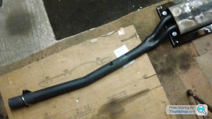
I'm struggling to think of one good reason why anyone would want to mount the sensor there.Access is difficult because it's under the car. You've got the potential for air leak at the slip joint to the Y piece. And it's a looooong way from the combustion chamber and there will be a time lag between the throttle and revs position and combustion event , and that gas being read by the sensor.
Most bizarre choice.

Access for inserting the sensor was not difficult, I did fit that and not being a service item wont need regular attention and the wiring is a lot tidier as it is not in the engine bay.
If the exhaust pipe is assembled correctly at the joint there will be no exhaust gas leak.
Regarding the time lag etc, that at present is debatable 'cause I know bugger all about it, but PO did and that is why it is positioned where it is.
The only thing bizarre it is that the PO couldn't transport the system in one piece to be altered so he cut it as can be seen in the photo and was going to use a horrible sleeve clamp for a joint. now that would have been difficult to fit and seal so I welded the pipe up and sold the clamp.
I didn't get round to finish the restoration the PO started.
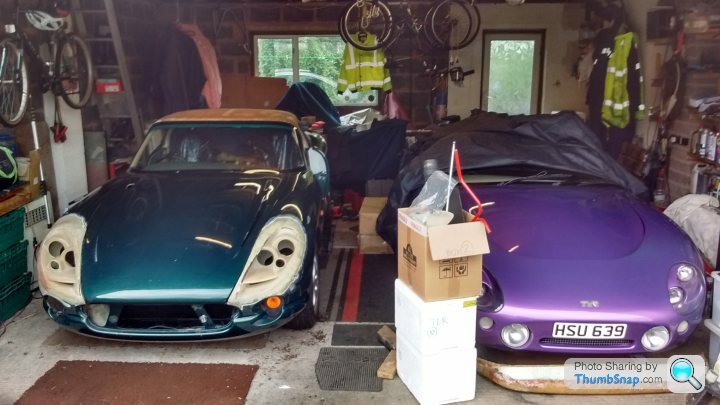
Here it is waiting for collection on Sunday.

What a strange and unaccessible place to put the boss!
I seem to remember measuring my spare exhaust very accurately for the guy to weld back together correctly.
What I did notice changing exhausts on my mates Volvo was the lambda is positioned way down the line and in a similar place to the one above but I agree with Joolz, the sooner you get those readings the better.

That because your mates sensor Alun was located post cat this is to monitor cat efficiency/function  and agree the TVR exhaust above thats a ridiculous (for reasons already stated) location for a WB sensor, it also liable to thermal/quench shock if up to temp and runs through a flash flood or similar WB sensors tolerate little abuse inc impact
and agree the TVR exhaust above thats a ridiculous (for reasons already stated) location for a WB sensor, it also liable to thermal/quench shock if up to temp and runs through a flash flood or similar WB sensors tolerate little abuse inc impact Can you guys remember where you connected in the map sensor?
I'm aware it's supposed to be teed into the fuel pressure regulator line but my map connection at the ECU is only 3.5 mm diameter and the pressure regulator line is about 5 mm.
I don't seem to be able to find the relevent reducers to do this.
I'm aware it's supposed to be teed into the fuel pressure regulator line but my map connection at the ECU is only 3.5 mm diameter and the pressure regulator line is about 5 mm.
I don't seem to be able to find the relevent reducers to do this.
I drilled and tapped a new hole in the trumpet base, alongside the crankcase breather connection, to take a small barbed fitting. These are readily available on eBay.
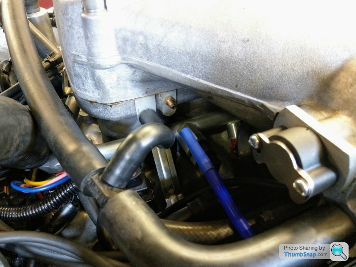
As an aside, I've never for some reason liked the MS idea of taking the vacuum tube all the way to the ECU when you're taking lots of wire in that direction anyway and there's always a spare connector or two on the DB37. I use an external GM MAP sensor and short run of vacuum tube.
Dougal.
As an aside, I've never for some reason liked the MS idea of taking the vacuum tube all the way to the ECU when you're taking lots of wire in that direction anyway and there's always a spare connector or two on the DB37. I use an external GM MAP sensor and short run of vacuum tube.
Dougal.
Yes that's right, however, when using MAP as the primary load, throttle position, and all the other inputs, are used by the code to determine final fuel load.
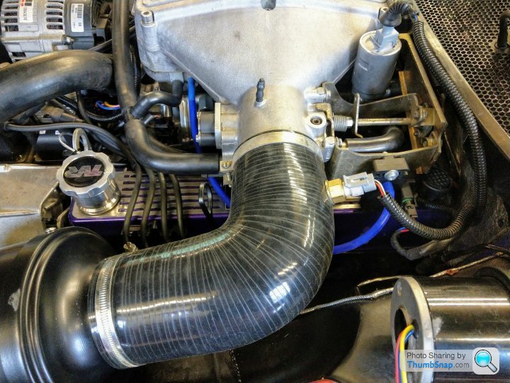
Regards the TPS, I found the standard Lucas one to have poor resolution, plus mine had fairly erratic readings and these where affected also by underbonnet heat. I changed to the Colvern TPS which has excellent resolution, a very smooth read-out and appears to be unaffected by heat. It could be mounted directly using a short length of modified throttle spindle but I preferred to take any stress off the sensor by mounting the spindle in a small bearing pressed into an aluminium mounting plate. Accurate TPS operation is also required for tuning of acceleration enrichment which relies solely on the TPS rate of change.
Dougal.
Can anyone tell me if fitting the trigger wheel to the crank pulley is much the same as this for a serp engine?
https://youtu.be/0GHldV2aKg4
https://youtu.be/0GHldV2aKg4

Belle427 said:
Any info you have on the plug lead numbering to coil packs would be handy to know.
Im going to be running vw style coil packs.
you will have two coil packs with two coils in each. How you or your installer wire the trigger wiring to each of the packs will determine which coils do which cylinders.Im going to be running vw style coil packs.
Each coil does 2 cylinders so in order for wasted spark to work they will always be this config...
1 - 6
8 - 5
4 - 7
3 - 2
If you are wiring this yourself i would start by doing a drawing of where the coils will sit and where the cylinders are. With this you can plan the neatest route for your leads. The layout will be completely different for coils sitting across the engine against the bulkhead compared to the coils mounted out over the water pump pulley.
Steve
So my conversion is complete and running, it all went reasonably smoothly. I did find some areas of it frustrating but it was an interesting project.
Shaun of Ms2 Tuning connected remotely to make some tweaks for me, the map actually feels pretty good on the road.
Proper mapping is the next stage but Shaun is 4 hours away and im struggling to get hold of Bailey performance at the moment.
Shaun of Ms2 Tuning connected remotely to make some tweaks for me, the map actually feels pretty good on the road.
Proper mapping is the next stage but Shaun is 4 hours away and im struggling to get hold of Bailey performance at the moment.
Gassing Station | Chimaera | Top of Page | What's New | My Stuff