Chimaera 4.0 ‘96 Fuel pump wont prime.
Discussion


Trying to get to the bottom of why my Chimaera won’t start…. And know this may be a similar line to lots of other posts on the forum.
Basic description that everyone knows. Disarm alarm, and put ignition into activate, but not start – Don’t hear the fuel pumps priming.
Assumed first thing to try – ECU and Fuel Pump relays in passenger footwell. They are both ‘clicking’ in. Have removed the relays and bench tested them both, and they appear to be fine.
Have added a bulb to the output of Fuel Relay, and it lights for 3 second on ignition – so assume 12v out of relays (Pin 87). Cable out of relay for me is White / Purple.
Disconnected the inertia switch, and applied +12v to the output, and the fuel pump runs. So I assume from inertia switch to fuel pump ok.
Have bridged the inertia switch, and turned on ignition, and fuel pump doesn’t prime (also tested for continuity across inertia switch and OK) so I assume its not the inertia switch. Output from Inertia switch yellow wire – input into inertia switch yellow / black wire.
In the first instance – have I missed anything obvious?
Secondly, how and where are the terminations between the white and purple wires out of the Fuel Pump Relay, (located in the passenger footwell) until it turns into the Yellow / Black wire that are the input into the inertia switch located under the passenger side dash?
I can see a black plug / socket I the footwell with linking wires, but all appear to be back - so even if this is in circuit, they must also connect in at least one other place.
Looking at the schematic on page 270 of the bible, there appears to be a block F:G coming back from the Yellow / Black input into the inertia switch. Any ideas what this is? What colour? Where in the car?
Any help greatly accepted
thanks
As you have 12v after the relay, there are 2 possibles.
1. Push the passenger seat fully forward and tilt it. On the back of the B pillar carefully pull the carpet away - held by velcro - and you will find a large opening. Look inside and you will see some multiplugs linking the rear of the car to the front. Disconnect the fuel pump connector - the colours from the pump are easy to see - and use either contact cleaner or WD40 and spray the connectors. Reconnect and try again. This is a very common problem.
2. Apply 12v directly to the pump positive terminal to ensure it has not seized up especially if it has been standing a long time. Also check the earth wire is making good contact if it is attached to the chassis nearby.
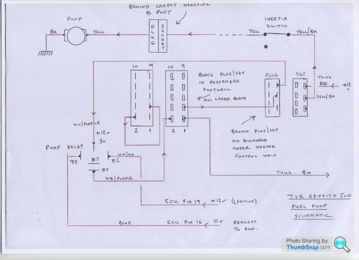
Thank the owner of this website http://www.bertram-hill.com/fuel-pump-schematic.ht...
I think this will help
I think this will help
Hi
N7GTX - Thanks for the info re the wires behind passenger B Pilar. Didn't know they were there.
However, I cant see either a white with purple wire (output from the Fuel Relay) or Yellow Black (input to the inertia switch).
I have just made a bridge directly out of the fuel relay into the output of the inertia switch, and that primes the pump as expected (both signifying the connections to the pump and earth from the pump ok, and also that the fault lies somewhere between the two). BUT WHERE.....
Penelope Pitstop, I had seen that diagram, but still cant find either a black connector with the white / purple wire going in, or a brown connected block anywhere on my car.
Belle427 Could be through the immobiliser, but the diagrams I have managed to find on line don't show this? Not sure how I could find out, as cant find where the white / purple wire goes
http://www.abacuscaralarms.co.uk/tvr-alarms.html
https://www.pistonheads.com/gassing/topic.asp?h=0&...
https://www.pistonheads.com/gassing/topic.asp?h=0&...
Edited by Penelope Stopit on Tuesday 3rd July 18:49
Fuel relay has two pins marked 87.
One has two white/orange wires which go to the Lambdas.
The second has two wires a white/Purple and a black. The white purple goes to the carbon canister purge valve. Which leaves the black wire which is for the fuel pump. This black wire goes to a connector positioned at top of passenger footwell over the tunnel and sort of under the dash. So black goes into the connector Pin 2 and comes out the other side as Yellow/Black and on to the Immobiliser connector. The output from the immobiliser then goes inertia switch.
So my guess would still be with immobiliser.
Has anyone suggested doing a hard reset by disconnecting the battery for a few minutes then reconnect.
Steve
If it turns out to be the immobiliser I’d try to identify the other circuit cut for your own peace of mind so it can be found easily if the car breaks down.
I’d probably bypass it altogether if it’s started to fail now, inexpensive modern immobilisers can be fitted easily.
You could retain the central locking of the original system or if your competent change the whole thing.
These are pretty good and no messing with pressing buttons to disarm, just the immobiliser part.
https://www.ebay.co.uk/itm/Toad-Sterling-Excel-Tha...

cheltgar said:
Thanks Steve and chimpongas
I have tried hard reset by disconnecting battery
If I have a dodgy immobiliser, understand how to bypass this circuit now, will try tomorrow, but are there any other circuits I should also bypass?
Thanks in advance
If you PM me I will send by return my simple to follow and completely reversible step by step bypass instructions with supporting photos and wiring diagram.I have tried hard reset by disconnecting battery
If I have a dodgy immobiliser, understand how to bypass this circuit now, will try tomorrow, but are there any other circuits I should also bypass?
Thanks in advance
It helps to understand the immobiliser element of the Meta security system is really nothing more than an interrupter switch on the ECU and starter solenoid circuits, it's just in this case it's a switch you remotely turn on and off with an IR fob rather than manually with your finger.
So with this understood there's nothing to stop you replacing a sick immobiliser with a simple 12v latching switch

Obviously a replacement security system is better, but don't dismiss the very real reliability benefits of keeping things simple, and you can't get more simple than a carefully hidden one of these

100% reliability for less than a quid!
ChimpOnGas said:
If you PM me I will send by return my simple to follow and completely reversible step by step bypass instructions with supporting photos and wiring diagram.
It helps to understand the immobiliser element of the Meta security system is really nothing more than an interrupter switch on the ECU and starter solenoid circuits, it's just in this case it's a switch you remotely turn on and off with an IR fob rather than manually with your finger.
So with this understood there's nothing to stop you replacing a sick immobiliser with a simple 12v latching switch
Obviously a replacement security system is better, but don't dismiss the very real reliability benefits of keeping things simple, and you can't get more simple than a carefully hidden one of these
100% reliability for less than a quid!
Dave can you send me your instructions also please. It helps to understand the immobiliser element of the Meta security system is really nothing more than an interrupter switch on the ECU and starter solenoid circuits, it's just in this case it's a switch you remotely turn on and off with an IR fob rather than manually with your finger.
So with this understood there's nothing to stop you replacing a sick immobiliser with a simple 12v latching switch
Obviously a replacement security system is better, but don't dismiss the very real reliability benefits of keeping things simple, and you can't get more simple than a carefully hidden one of these
100% reliability for less than a quid!
Many thanks Al


Gassing Station | Chimaera | Top of Page | What's New | My Stuff