Door Lock Relay
Discussion


Loubaruch said:
Like Belle247 I also fitted a Toad (Sterling One) alarm/Immobiliser to replace the original Meta that in my case was failing to operate the door locking reliably.
The Toad does require the external door lock relay module but I believe TVR Parts stock these.
The Toad is superior in several aspects to the factory fitted Meta system:
The relays that provide immobilisation are heavy duty items as opposed to the light duty items in the Meta.
By adding an additional relay remote boot lid switching was achieved
It was significantly less expensive than the current Meta replacement
I also omitted the internal alarm function as in an open car it can be far more trouble than its worth
By omitting the internal alarm function the alarm category I believe is downgraded from Thatcham 1 to 2.
The system was fitted 2 years ago and has been fault free.
An alarms interior protection function must be used for Thatcham category 1 approval and certification of installationThe Toad does require the external door lock relay module but I believe TVR Parts stock these.
The Toad is superior in several aspects to the factory fitted Meta system:
The relays that provide immobilisation are heavy duty items as opposed to the light duty items in the Meta.
By adding an additional relay remote boot lid switching was achieved
It was significantly less expensive than the current Meta replacement
I also omitted the internal alarm function as in an open car it can be far more trouble than its worth
By omitting the internal alarm function the alarm category I believe is downgraded from Thatcham 1 to 2.
The system was fitted 2 years ago and has been fault free.
Should an insurance company require a Thatcham category 1 alarm to be fitted, the owner would need to have the alarm installed by an approved installer that will issue a certificate on completion of installation and testing
Thatcham category 2 is an immobiliser
Edited by Penelope Stopit on Tuesday 20th August 12:17

 Cobra CAT 1 been trouble free for 12 years
ChimpOnGas said:
Does anyone have a picture or sketch to show the connections of the door lock relay module? I'm making a wiring loom design and want to know which wire goes to which blade on the lock module. I can see the numbering on the front but can't see how the IDs relate to the blades and don't have one available to me right now. Any help much appreciated!
Can't do a photo at present as new phone has a different connector so I now need to buy all new leads. Damn.
I will try and draw you a picture
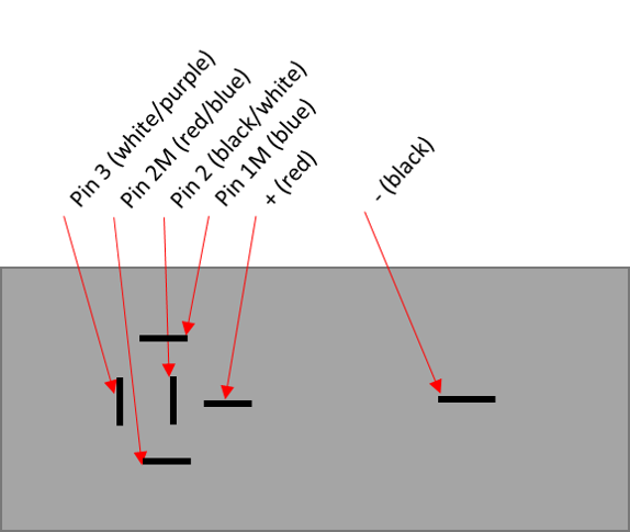
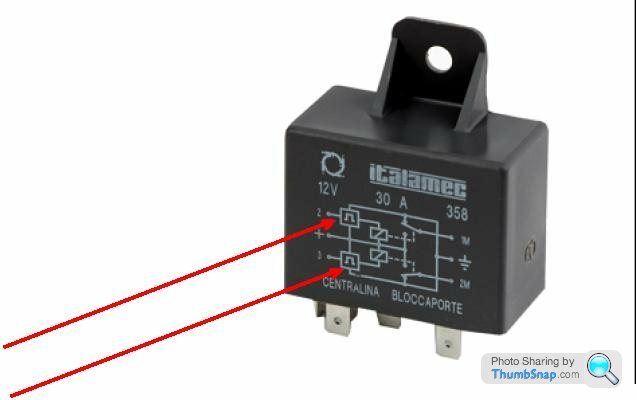
Stand the module on its end and look at the pins. At the top is a cluster of 5 pins in the same layout as a 5 pin relay. (They won't line up no matter how many spaces I put in)
__
I __ I
I
Top horizontal is pin 3 white/purple wire.
Middle horizontal is pin 2 black/white wire x 2
To left of pin 2 is vertical pin 2M red/blue wires x 2
To right of pin 2 is vertical pin 1M blue wires x 2
below pin 2 is vertical pin + red wires x 2
Lower down the module on the right is pin marked earth black wire.
I've drawn my own wiring diagrams if they are any help to you.
Steve
I will try and draw you a picture
Stand the module on its end and look at the pins. At the top is a cluster of 5 pins in the same layout as a 5 pin relay. (They won't line up no matter how many spaces I put in)
__
I __ I
I
Top horizontal is pin 3 white/purple wire.
Middle horizontal is pin 2 black/white wire x 2
To left of pin 2 is vertical pin 2M red/blue wires x 2
To right of pin 2 is vertical pin 1M blue wires x 2
below pin 2 is vertical pin + red wires x 2
Lower down the module on the right is pin marked earth black wire.
I've drawn my own wiring diagrams if they are any help to you.
Steve
Edited by Steve_D on Tuesday 19th January 09:19
Penelope Stopit said:
Have you considered or decided in fitting an all singing and dancing alarm system?
If answer is that you have decided to fit new, CDL circuits will be built into the new alarm unit and all the TVR units and wiring will then become reduntant, really does tidy the job up much
Not really, I haven't decided on an alarm yet though to be honest I don't like alarms - they aren't really hard to shut up if you want to steal the car so my thought is that for my build I just want to have a nice key fob that locks and unlocks the doors and pops the boot when I press a button. I'll fit an immobiliser and a tracker of some sort but probably won't bother with an alarm or intrusion sensors. If answer is that you have decided to fit new, CDL circuits will be built into the new alarm unit and all the TVR units and wiring will then become reduntant, really does tidy the job up much
So with that in mind, my current thought would be something like an autowatch 457 like I have on my existing Chim with some of the functions unused, or if I can find a system with a nicer modern looking flip out key fob then I might do that - any suggestions?
The main reason is that I'm binning the whole wiring loom and am currently designing a new one as part of my project rocket build which will (almost) completely rid the car of fuses and relays and will run all inputs and outputs through a Life Racing PDU system. In this way, the door buttons and remote locking functions will give input requests and the PDU will lock or unlock the doors etc upon request. This should mean I can do some interesting things like if the battery is getting too low pop the boot automatically or even the drivers door too. Maybe disable the door opening when the car is moving above a certain speed and some other logic to make it a little bit smarter and more usable.
The only trouble is that the lock solenoid requires the flow of current to be reversed to lock and unlock and the PDU won't be able to perform that function, so probably the only relay in the car will be this door lock relay.
Edited by 450Nick on Tuesday 19th January 11:04
Steve_D said:
Can't do a photo at present as new phone has a different connector so I now need to buy all new leads. Damn.
I will try and draw you a picture
Stand the module on its end and look at the pins. At the top is a cluster of 5 pins in the same layout as a 5 pin relay. (They won't line up no matter how many spaces I put in)
__
I __ I
I
Top horizontal is pin 3 white/purple wire.
Middle horizontal is pin 2 black/white wire x 2
To left of pin 2 is vertical pin 2M red/blue wires x 2
To right of pin 2 is vertical pin 1M blue wires x 2
below pin 2 is vertical pin + red wires x 2
Lower down the module on the right is pin marked earth black wire.
I've drawn my own wiring diagrams if they are any help to you.
Steve
Thanks very much Steve! That's extremely helpful, so does this look correct?I will try and draw you a picture
Stand the module on its end and look at the pins. At the top is a cluster of 5 pins in the same layout as a 5 pin relay. (They won't line up no matter how many spaces I put in)
__
I __ I
I
Top horizontal is pin 3 white/purple wire.
Middle horizontal is pin 2 black/white wire x 2
To left of pin 2 is vertical pin 2M red/blue wires x 2
To right of pin 2 is vertical pin 1M blue wires x 2
below pin 2 is vertical pin + red wires x 2
Lower down the module on the right is pin marked earth black wire.
I've drawn my own wiring diagrams if they are any help to you.
Steve
Edited by Steve_D on Tuesday 19th January 09:19
Am a hater of car alarms but felt it best to pop the question
Yes, am following project rocket and couldn't resist studying about the PDUs and their capabilities, may have posted to your topic in the past about liking the PDUs
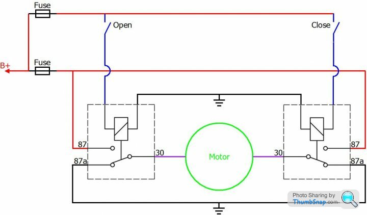
Understand your problem with revering the polarity and have what you may or may not consider to be a better solution
Put together the following diagram for someone that needed to reverse polarity window motors
You may or may not choose similar switching for project rockets windows circuit
Ignore the open and close switches as your PDU outputs will be doing the switching
Yes, am following project rocket and couldn't resist studying about the PDUs and their capabilities, may have posted to your topic in the past about liking the PDUs
Understand your problem with revering the polarity and have what you may or may not consider to be a better solution
Put together the following diagram for someone that needed to reverse polarity window motors
You may or may not choose similar switching for project rockets windows circuit
Ignore the open and close switches as your PDU outputs will be doing the switching
Thanks for the info! Yes I had thought about a pair of relays but then individual relays are notoriously hard place in a car with any degree of neatness, so I figured the original lock relay solution effectively does the same job but in a neat package that can be installed quite neatly. I've found a place that sells new ones so unless there's a tidier solution then I'll probably just go with that.

450Nick said:
Thanks for the info! Yes I had thought about a pair of relays but then individual relays are notoriously hard place in a car with any degree of neatness, so I figured the original lock relay solution effectively does the same job but in a neat package that can be installed quite neatly. I've found a place that sells new ones so unless there's a tidier solution then I'll probably just go with that.
You're welcomeYes the CDL relay does the same job and also has a preset timer circuit
Penelope Stopit said:
Ok then
What's you plan of attack on the windows circuit?
From memory the window motor has a 3 pin connector with a common earth and 12v to each of the other pins for up or down, so had just planned to use a dedicated output for up and down for each window. The PDU can sense when the motor stalls and stop current so can program in auto down or up.What's you plan of attack on the windows circuit?
Gassing Station | Chimaera | Top of Page | What's New | My Stuff