Door Lock Relay
Discussion


I was.... What do you know about them? On my old Chimaera the windows were rather slow on the drivers side so I bought a new one, pulled the mechanism apart and changed everything and found the new one to be no faster really. While the door was off though I put a 12v battery charger directly onto the terminals of the motor and it shot up so I figured the problem was simply not enough amps getting in. There's no relay and the full power goes through the switch so the voltage drop is significant. My thought was that the PDU will take a 5v input from the window buttons then will shoot a nice strong 12v+ directly to either side of the motor with amply sized cable - this should fix the issue. If it doesn't then I'll try a different motor maybe.
Know that the standard fit motors are 2 wire permanent magnet
Bearing in mind I only know of the permanent magnet type used by several manufacturers and think all manufacturers use permanent magnet, the PDU switching method for reversing the polarity to the window motors is the same as reversing the polarity to the central locking motors (complicated if possible)
Is it possible that you will end up using too many PDU circuits for window motor switching?
Am I right in thinking that the method you mention above and plan to use is for the PDU switching being a positive output for window up and a positive output for window down using a possibly nonexistent 3 wire motor (I don't know of any)
Yes, many window motor circuits suffer from volt-drop, relays fitted and wired close to the motors are a common fix, some manufacturers do use motors with relays built-in as a single unit
Edited by Penelope Stopit on Wednesday 20th January 11:58
Been commenting about PDUs yet meant had viewed the PMUs https://www.ecumaster.com/files/PMU/PMU_Manual.pdf
Now found https://www.liferacing.com/products/pdus/
Wondering if a purpose built or readily available polarity reverser used in conjunction with/running alongside a PDU would make life easier for you
Positive PDU output can still supply motors through relays or control units and the circuits would still have PDU over-current sensing
2 x Relays as a sealed unit in each door supplied by PDU???????????????
Only ideas
Simply thinking/posting out loud
Edited by Penelope Stopit on Wednesday 20th January 12:29
Good discussion! It seems I must have a hazy memory as I could have sworn that there were 3 wires... Logically speaking though I think you're right so I will need to do something different. Yes I'm currently planning to use the PDUx4 so number of outputs won't be a problem, but indeed reverse polarity circuits might be.
WAIT. I just re-read the datasheet a little bit more thoroughly and realised that it has 5 pairs of full bridge outputs so it can control reverse polarity on 5 circuits up to 40amps each. Nice!
Well turns out I won't need one of those relay modules after all. Brilliant!
WAIT. I just re-read the datasheet a little bit more thoroughly and realised that it has 5 pairs of full bridge outputs so it can control reverse polarity on 5 circuits up to 40amps each. Nice!
Well turns out I won't need one of those relay modules after all. Brilliant!
Edited by 450Nick on Friday 22 January 02:42
Penelope Stopit said:
All's good then, no relays, heaven
PDUx4. That's a hell of a lot of outputs for one unit, could reverse a space rocket with one of those
PDUx4. That's a hell of a lot of outputs for one unit, could reverse a space rocket with one of those
 yeah it is a bit of a beast... I started with the x3 but I just about ran out of outputs so for the moment it's x4 but I'm still working through a bunch of things so I might be able to get rid of a few outputs. I'm looking at the possibility of using new Bosch OEM direct drive wiper motors that can be controlled with LIN or CAN bus - that'll be at least a couple saved if I can go with that.
 I'm using a program called RapidHarness to do the harness design - amazingly powerful for this job. Next question is going to be wing mirror motors... How the hell do they work? Do you happen to have a wiring schematic - I'll probably get into that one this weekend...
Steve D has drawn some nice diagrams
Remember discussing Bosch motors with you over at PH project rocket
Have never used software for wiring harness building but can imagine it being much fun
Here's a schematic that am working on, not joined the DOTS yet and missing some components
Feel free to finish the work for me

Joking apart (might never get that diagram finished)
Here's a not so clear diagram complete
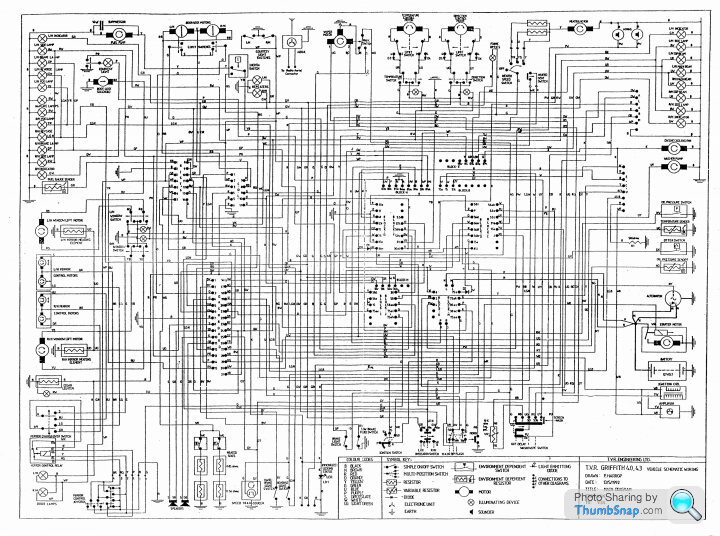
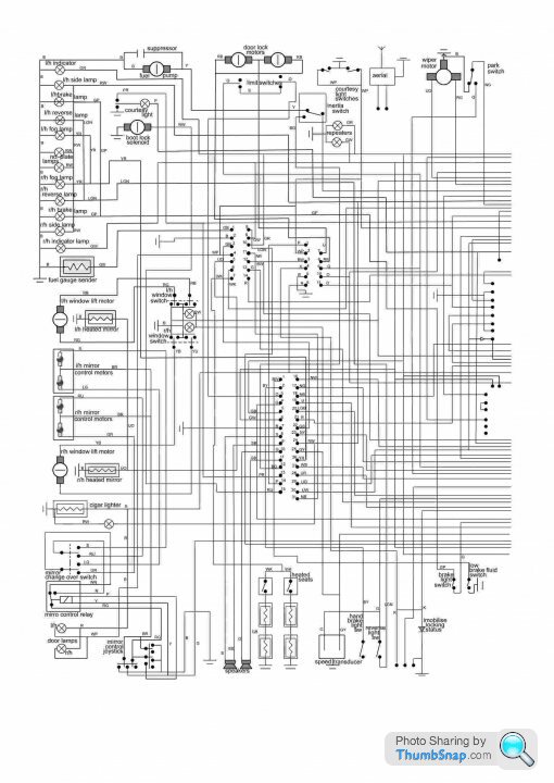
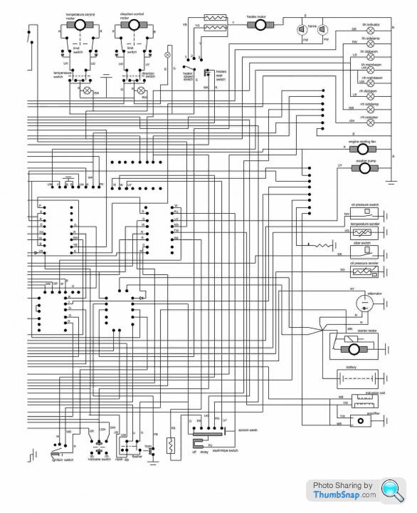
Here's a clearer one in 2 halves
Have fun
Remember discussing Bosch motors with you over at PH project rocket
Have never used software for wiring harness building but can imagine it being much fun
Here's a schematic that am working on, not joined the DOTS yet and missing some components
Feel free to finish the work for me
Joking apart (might never get that diagram finished)
Here's a not so clear diagram complete
Here's a clearer one in 2 halves
Have fun
Penelope Stopit said:
............Joking apart (might never get that diagram finished)........................
I looked at re-drawing those diagrams but decided they were next to useless as the circuits terminate at the point where they disappear into the fuse/relay box or the 'dashboard' so they offer no insight as to how the circuit works.This is why I produced my own.
PM me if anyone wants them.
Steve
Steve_D said:
Penelope Stopit said:
............Joking apart (might never get that diagram finished)........................
I looked at re-drawing those diagrams but decided they were next to useless as the circuits terminate at the point where they disappear into the fuse/relay box or the 'dashboard' so they offer no insight as to how the circuit works.This is why I produced my own.
PM me if anyone wants them.
Steve
What I had planned was to add the fusebox internal circuits
With building the diagram using diagram drawing software that will work with layers, was considering drawing each circuit as a layer and then saving all those layers plus add them all together, all can be saved as image files, would be left with a complete circuit diagram plus individual circuit diagrams
Time is the problem
Penelope Stopit said:
I agree, they are definitely lacking information
What I had planned was to add the fusebox internal circuits
With building the diagram using diagram drawing software that will work with layers, was considering drawing each circuit as a layer and then saving all those layers plus add them all together, all can be saved as image files, would be left with a complete circuit diagram plus individual circuit diagrams
Time is the problem
Those diagrams have been around for many many years, you just copied them ! So you don’t seem to of been working on them very much. I guess without a tvr it’s going to take you a while ! I can’t talk, I have a mustang gt !
David Beer said:
Those diagrams have been around for many many years, you just copied them ! So you don’t seem to of been working on them very much. I guess without a tvr it’s going to take you a while ! I can’t talk, I have a mustang gt !
Don't be nastyAm hoping that the diagrams posted are of some use, never have claimed to have drawn them, have simply posted them here
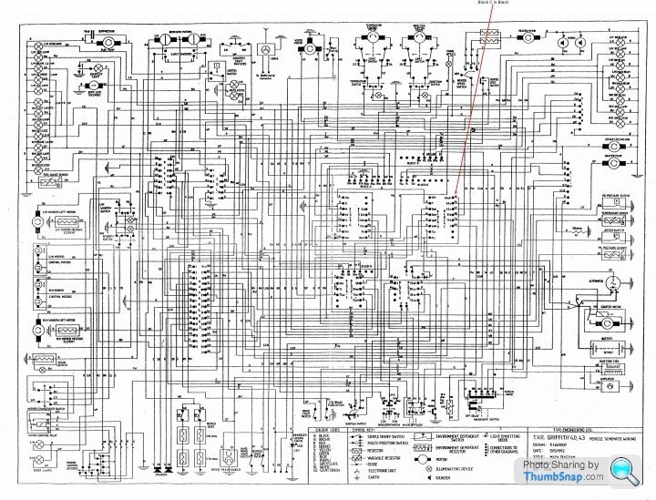
Spent much time adjusting the sizes of those 2 halves and cropping them until nearly achieving a perfect merging of them, the method used has up to now allowed the drawing of the below image that shows plugs, exterior lights, warning lights and motors
Penelope Stopit said:
Don't be nasty
Am hoping that the diagrams posted are of some use, never have claimed to have drawn them, have simply posted them here
Spent much time adjusting the sizes of those 2 halves and cropping them until nearly achieving a perfect merging of them, the method used has up to now allowed the drawing of the below image that shows plugs, exterior lights, warning lights and motors
Oh ok, carry on. Didn’t see that difference. Am hoping that the diagrams posted are of some use, never have claimed to have drawn them, have simply posted them here
Spent much time adjusting the sizes of those 2 halves and cropping them until nearly achieving a perfect merging of them, the method used has up to now allowed the drawing of the below image that shows plugs, exterior lights, warning lights and motors
Steve_D said:
Penelope Stopit said:
............Joking apart (might never get that diagram finished)........................
I looked at re-drawing those diagrams but decided they were next to useless as the circuits terminate at the point where they disappear into the fuse/relay box or the 'dashboard' so they offer no insight as to how the circuit works.This is why I produced my own.
PM me if anyone wants them.
Steve
Hold on a minute
Those diagrams are very useful for point to point continuity testing
They would be more useful if the relays and fuses circuitry were added to them or posted below them
Your diagrams aren't of much use unless used alongside the above diagrams, and, diagrams or images of fusebox termination points and relay apertures
Criticising diagrams that assist users of your diagrams to be able to understand them is bizarre
It's a human trait expecting others to understand something that doesn't include all the information needed to be able to understand it
Something positive has come from you criticising the above diagrams
Think about it
Example
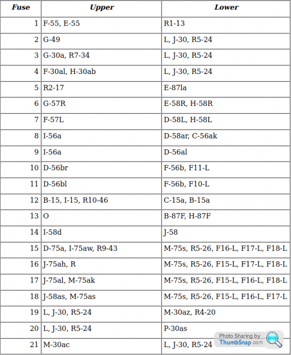
A snippet from a diagram
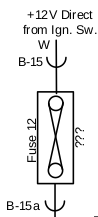
shows termination points B15 and B15a, there is no much needed information about the termination points
A recent post to another topic shows the information needed
Penelope Stopit said:
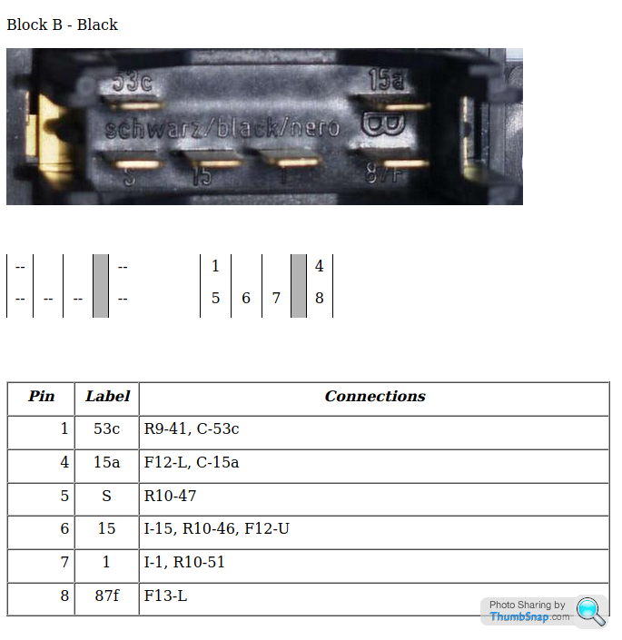
See below images that relate to fusebox plug B (Black Plug) this is the plug that the supply from the ignition switch goes into for fuse 12 and exits from to supply the blue loop-back block
As can be seen in the second image, supply from ignition switch goes in at Black Plug B Terminal 15 and exits at Black Plug B Terminal 15a
As can be seen in the second image, supply from ignition switch goes in at Black Plug B Terminal 15 and exits at Black Plug B Terminal 15a
Edited by Penelope Stopit on Saturday 23 January 10:03
450Nick said:
Next question is going to be wing mirror motors... How the hell do they work? Do you happen to have a wiring schematic - I'll probably get into that one this weekend...
Know that a different mirror with 1 x motor and 1 x solenoid can simplify the job (Chimaera mirrors have 2 x motors), something in the back of my mind is telling me that Steve D has a diagram for a Corrado Mirror conversion using the original switches yet not needing a relay, VW Corrado mirrors have 1 x motor and 1 x solenoidFound the topic
https://www.pistonheads.com/gassing/topic.asp?h=0&...
That includes
Steve_D said:
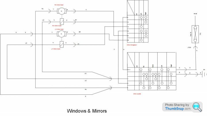
This is all you need
Steve
Steve
Penelope Stopit said:
Don't be nasty
Am hoping that the diagrams posted are of some use, never have claimed to have drawn them, have simply posted them here
Spent much time adjusting the sizes of those 2 halves and cropping them until nearly achieving a perfect merging of them, the method used has up to now allowed the drawing of the below image that shows plugs, exterior lights, warning lights and motors
Me stupid,what do those dots mean. ? Maybe when you post the information is not shown. Am hoping that the diagrams posted are of some use, never have claimed to have drawn them, have simply posted them here
Spent much time adjusting the sizes of those 2 halves and cropping them until nearly achieving a perfect merging of them, the method used has up to now allowed the drawing of the below image that shows plugs, exterior lights, warning lights and motors
Edited by David Beer on Sunday 24th January 08:18
David Beer said:
Penelope Stopit said:
Don't be nasty
Am hoping that the diagrams posted are of some use, never have claimed to have drawn them, have simply posted them here
Spent much time adjusting the sizes of those 2 halves and cropping them until nearly achieving a perfect merging of them, the method used has up to now allowed the drawing of the below image that shows plugs, exterior lights, warning lights and motors
Me stupid,what do those dots mean. ? Maybe when you post the information is not shown. Am hoping that the diagrams posted are of some use, never have claimed to have drawn them, have simply posted them here
Spent much time adjusting the sizes of those 2 halves and cropping them until nearly achieving a perfect merging of them, the method used has up to now allowed the drawing of the below image that shows plugs, exterior lights, warning lights and motors
Need to click for bigger diagrams, have added pointers to Fusebox Termination Point Block C on both of them
There is a loom plug of blue colour that plugs into Block C
All the rows of DOTS are termination points and are coloured to match the colours of the wiring harness plugs, makes life much easier for the users of the diagram
This is why many of my posts make it look like I'm on drugs and talking to myself, they sometimes go on and on and on........The thing is, I don't know what people do and don't understand about a circuit being discussed, hence attempt to explain everything in a clear way
Should the work ever be completed, someone some day might benefit from a coloured and decently labelled diagram that includes additions such as relays and fuses
Stay safe

Gassing Station | Chimaera | Top of Page | What's New | My Stuff