Jobs, Progress and Questions!
Discussion


LLantrisant said:
all bolts looks to be inox, besides the one holding the coil-bracket...its a galvanized......which immediately identifies the typical "built in a shed at home" mentality.
do it once , do it right.
there is no excuse :" but i could get the longer bolt for the moment just in galvanized" "i will change it later" "its just a temporary solution"
i beg it will be there even in 3 years.
Ok, so this is my ignorance, why is galvanised bad? I was intending on replacing all of the bolts with those, I got a set, when I take the Plenum off.do it once , do it right.
there is no excuse :" but i could get the longer bolt for the moment just in galvanized" "i will change it later" "its just a temporary solution"
i beg it will be there even in 3 years.
Edited by LLantrisant on Saturday 31st August 08:49
Having a 1 year old doesn’t leave huge amounts of time so I need to choose my battles as it were.

Most things I’ve done so far are when I’m supposed to be working and the wife is out!
Ok, got it 
I didn’t actually buy them because they were cheap, I got them because they were the right size, so have no issue changing to stainless.
The cost isn’t really the problem, it’s the deliveries! The wife hates having more stuff in the house! eBay is good because I can send it to Argos and pick it up when she isn’t around!
You will all be delighted to know, I am sure, that a set of stainless bolts, washers and copper grease is all winging its way to my nearest Argos so I can sneak it past the Mrs and fix my heinous error. 
Unfortunately buying things is currently the only "work" I have had time to do, for now.
Unfortunately buying things is currently the only "work" I have had time to do, for now.
Time this morning was found for some work!
Reading the Bible, Mr Heath says that if BOTH lamba's are showing an error then it is likely the heater supply to both probes. So I thought I would check the fuse for the heater, and of course, after looking at various fuse box layouts, mine seems to adhere to this one (it is a 1997 car) -

However, as you can see from my actual fuse box, the "Blank" one above has a 10AMP fuse in it. Also, the slot (14) that is for the heater has a 20AMP fuse in it, not a 15. My heater fan works, but I haven't had a chance to run the car out to check the heat from it, and the fuse is not blown, but this concerns me that it may have killed both lambda sensors. I'll put a 15AMP fuse in, and will try and get my probes into the back of the lambda's themselves when I can run the car next (I don't really want to start buying new lambda's if I don't have to, and the US Ebay seller, Global Automotive doesn't appear to have any, I did ask them).

I checked all of the 15 amp fuses and the one in slot 6 was blown, so I put a replacement in (seemed odd that it was the alarm and hazards, they worked fine, when I broke down), and I hadn't worked out which layout my fuse box was while in there. It was a cheapy one though so I need to source some decent ones - any suggestions on a good fuse supplier?
Basically, my fuse box layout is confusing me. Am I right in thinking someone has put the wrong fuses in some slots?
Moving on from there, I decided to check the 2 resistors from the coil to the ECU and rev counter. OOOOOHH boy.
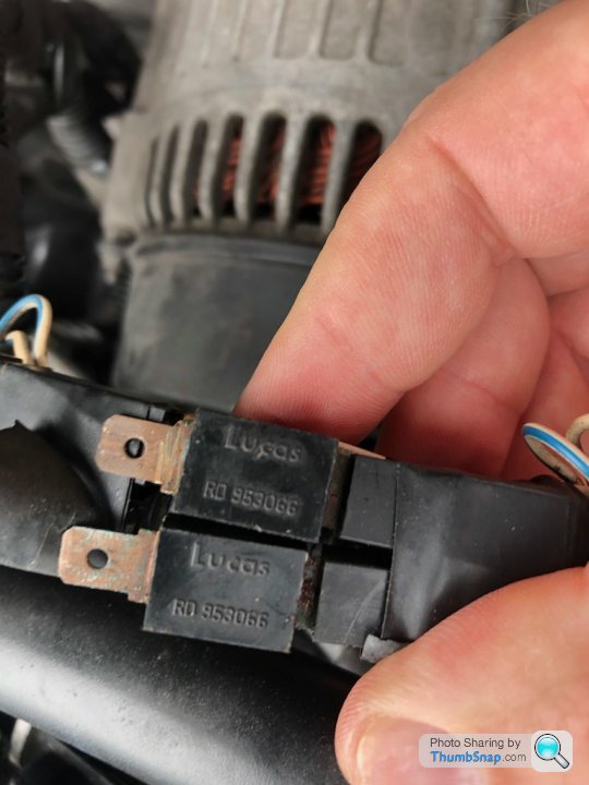
The otherside was worse. I sprayed some contact cleaner on them, and into the connections to/from the loom and then cleaned up the resistor contacts fully. The insides of the connectors looked fine though.
One resistor reads spot on, the other seems to be a bit high. Both have identical part numbers on them, so they should be the same. I got no reading at all from the one reading high before I cleaned it up.


I'll go ahead and see if I can find some replacements. I'm going to wrap them up once replaced as well, to try and prevent that corrosion again.
Reading the Bible, Mr Heath says that if BOTH lamba's are showing an error then it is likely the heater supply to both probes. So I thought I would check the fuse for the heater, and of course, after looking at various fuse box layouts, mine seems to adhere to this one (it is a 1997 car) -
However, as you can see from my actual fuse box, the "Blank" one above has a 10AMP fuse in it. Also, the slot (14) that is for the heater has a 20AMP fuse in it, not a 15. My heater fan works, but I haven't had a chance to run the car out to check the heat from it, and the fuse is not blown, but this concerns me that it may have killed both lambda sensors. I'll put a 15AMP fuse in, and will try and get my probes into the back of the lambda's themselves when I can run the car next (I don't really want to start buying new lambda's if I don't have to, and the US Ebay seller, Global Automotive doesn't appear to have any, I did ask them).
I checked all of the 15 amp fuses and the one in slot 6 was blown, so I put a replacement in (seemed odd that it was the alarm and hazards, they worked fine, when I broke down), and I hadn't worked out which layout my fuse box was while in there. It was a cheapy one though so I need to source some decent ones - any suggestions on a good fuse supplier?
Basically, my fuse box layout is confusing me. Am I right in thinking someone has put the wrong fuses in some slots?
Moving on from there, I decided to check the 2 resistors from the coil to the ECU and rev counter. OOOOOHH boy.
The otherside was worse. I sprayed some contact cleaner on them, and into the connections to/from the loom and then cleaned up the resistor contacts fully. The insides of the connectors looked fine though.
One resistor reads spot on, the other seems to be a bit high. Both have identical part numbers on them, so they should be the same. I got no reading at all from the one reading high before I cleaned it up.
I'll go ahead and see if I can find some replacements. I'm going to wrap them up once replaced as well, to try and prevent that corrosion again.
Loubaruch said:
Thank you! And wow they are more expensive than I thought they would be.Steve_D said:
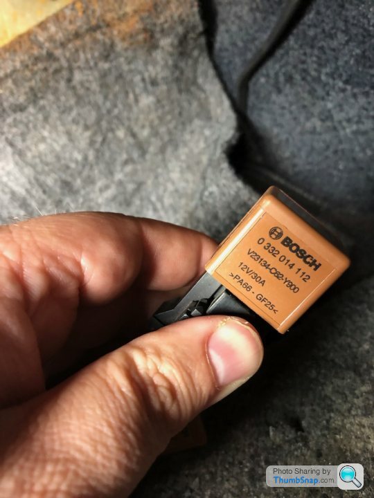
The lambda heaters are not fused. They are a direct supply from the fuel pump relay (white/orange wires). the fuse that supplies the relay has to be OK or the fuel pump would not work. If the Lambda heaters are not getting +12V then you may have the wrong type relay.
Steve
Ok, thank you. Steve
Both are the same, and Googling seems to indicate they are the right ones. Will check the lambda's directly next chance I get.
Belle427 said:
Got it, thank you.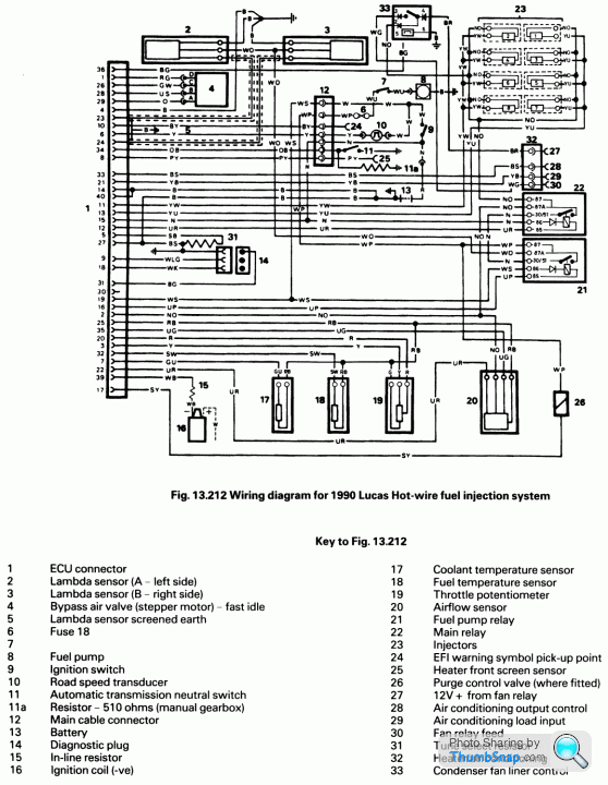
To confirm, the advice given here - https://www.actproducts.co.uk/2011/lucas-14cux-fue... on how to test the sensors, is that correct? I've seen a couple of threads that disagree so want to make sure before I stick probes in the sensors!
ACT said:
With the ignition switched off, test for continuity between the White ground wire and the engine block. There should be no resistance (i.e. a short circuit). Now set the multimeter to read Voltage, and insert the negative probe into the White ground wire, and the positive probe into the Red heater wire.
Now start the engine and check the voltage. There should be 12-14 Volts present when the engine is running, which is the supply for the sensor heater. This comes from the same relay that feeds the fuel pump, and shares the same fuse. If this supply is absent then the sensors will never give the correct reading.
Next the sensor signal itself should be probed. Leave the negative ground probe in the White ground wire, and put the positive probe into the Black signal wire. The voltage here should oscillate up and down between 0.2 and 1.2 Volts approximately 2 to 3 times per second. If the signal is stuck at 0 Volts or over 3.5 Volts then the sensor MAY be defective.
Re the resistors, I've ordered the RimmerBros ones. They are definitely pricier than what I was expecting for a resistor, but would prefer to use the "right" part. I ordered 2, even though one seems fine, a spare is always handy.Now start the engine and check the voltage. There should be 12-14 Volts present when the engine is running, which is the supply for the sensor heater. This comes from the same relay that feeds the fuel pump, and shares the same fuse. If this supply is absent then the sensors will never give the correct reading.
Next the sensor signal itself should be probed. Leave the negative ground probe in the White ground wire, and put the positive probe into the Black signal wire. The voltage here should oscillate up and down between 0.2 and 1.2 Volts approximately 2 to 3 times per second. If the signal is stuck at 0 Volts or over 3.5 Volts then the sensor MAY be defective.
Thanks, but how do you know which relay/connector does what? Should I just unplug one and see if the fuel pump primes?
And when you talk about the long lead test lamp, do you mean unplugging a lamdba connection and then putting another wire into the holes for the white and red leads from the lambda on the loom side to see if there is supply to it or do this from the relay connector?
And when you talk about the long lead test lamp, do you mean unplugging a lamdba connection and then putting another wire into the holes for the white and red leads from the lambda on the loom side to see if there is supply to it or do this from the relay connector?

Checked and found the right connector (it was blue), and tested each pin. Pin 30 did have a constant 12v, and the other 2 had 12V when the ignition was turned on and then dropped away.
Am going to make up a test lead with some circuit prototyping wiring I have around and an LED, for the lambda connections.
Am going to make up a test lead with some circuit prototyping wiring I have around and an LED, for the lambda connections.
No worries, all good learning, thank you.
One question - would leaving one lambda plugged in and then connecting the led up to the other connection put enough load on? Since both are throwing a code, its likely a problem in the wiring in the engine bay. I could easily swap it about as well, just to make sure. Or is that daft?
I definitely have some spare headlamp bulbs around I can use.
Yes, those are the connections. I've definitely misunderstood then, I thought both Lambda's were on the same circuit.
I'll see if I can find the second set of connections, I hadn't seem them while poking around.
My plug socks have shown up, so will hopefully have the time this weekend to do the plugs, HT leads (inc king lead), dizzy cap and rotor arm.
I know I am posting a lot of questions, but this is fun (for me). Almost as fun as actually driving the car. All the help is much appreciated!
I'll see if I can find the second set of connections, I hadn't seem them while poking around.
My plug socks have shown up, so will hopefully have the time this weekend to do the plugs, HT leads (inc king lead), dizzy cap and rotor arm.
I know I am posting a lot of questions, but this is fun (for me). Almost as fun as actually driving the car.
All the help is much appreciated!I actually have some good quality thermal CPU paste sitting around, so may do the swap. I didn't put gobs on, just enough and I did clean up the plate it mounts to before refitting. I did consider using the CPU paste, but assumed the stuff supplied would be sufficient.
I got the new resistors yesterday, they are unbranded so not Lucas (I guess I was expecting too much), but both read correctly so have put them in. However, after watching this video of Phazed's car - https://www.youtube.com/watch?v=fa5oKqEgkME (I browse PH a lot), his car does exactly the same thing on gear change, so I wonder if this is a case of "they all do it", although I am certain my old one didn't.
In Lambda news, I think they are both dead - https://www.youtube.com/watch?v=O0FZaWmf6c0 I found the connections both sides of the Plenum, simple when you know they are there! I used the probes in various places, on the different connections and got the same results, I just videoed those two. Shame I can't find them at a reasonable cost from that US eBay seller. Is it worth just buying one, testing it to make sure this is right? I assume if there was a break in the wiring somewhere I would be getting nothing. I did try 2 multimeters as well!
They were working, I saw them doing so on Rovergauge, so I do wonder if my misadventure with the ignition amp killed them, and somehow blew the fuse I replaced.
Re the blue relay, there is a white/orange and a white cable going into it on one 87 pin.
Well, I mean more when I drove the car and the ground for the ignition amp may have been suspect, which is what I would expect killed the previous amp. I could be wrong though!
Re the heater element, I assume for this I would disconnect the probe from the loom, and then test the resistance that way? Since there is only one heater wire, I assume I will still need to do this with the white wire and the black wire?
Re the heater element, I assume for this I would disconnect the probe from the loom, and then test the resistance that way? Since there is only one heater wire, I assume I will still need to do this with the white wire and the black wire?
Got it, thanks.
I did do some other tests, based on the ACT tests and I am now a bit confused.
I tested the resistance from the white wire to the engine block, on both, and that seemed fine. I also tested the voltage on the white and red wires, and this is where I am confused.
On the passenger side lambda, negative to white and positive to red, I got what I would have expected when testing white and black (according to ACT) - https://www.youtube.com/watch?v=PcaD6v_HgcQ
When I did the same to the drivers side lambda, nothing, no movement at all.
The passenger side seems fine, according to all of the tests, but it is still throwing an error code in the ECU. But, my wiring seems wrong, the signal is on the red wire and not the black one?
I haven't had a chance to check the heater elements. It was on my list for today (I had a car maintenance pass from the wife). Unfortunately, I didn't get time to get to them, due to a small calamity (perhaps I am the calamity), that I am hopeful I can fix without too much stress (I expect my hopes to be dashed here).
I had decided to start with plugs, leads, dizzy and rotor. Those Beru extender things are awful, and are now in the bin. The plugs were a LOT harder to get out than I expected, and I was being very careful. They all came out ok eventually, except the 2nd plug on the passenger/left hand side (number 3?). It took a fair bit of time and effort, but it came out. Unfortunately, I think the person who did this last threaded it partially and then managed to get it in, and now I cannot get it back in, and don't want to force it.
It looks to me that the thread further in is ok, so I have ordered this - https://www.amazon.co.uk/gp/product/B0086306NO I fully expect to be told this won't work and I am going to have to strip the engine to get it drilled out. I have also ordered a more "normal" thread chaser, as a cover all the bases, but I would rather the first one was successful.
I assume I should keep the above oiled/lubricated while using it?
I did carry on and replace the rest of the plugs, the dizzy cap, rotor and leads (the diagram in the bible did not match the orientation of my dizzy cap, but I just put it back how it was) and socks on the leads. Once this plug is sorted, the ignition refresh will be done.
This is a bit disheartening, but will hopefully get it sorted soon.
Or maybe I should buy that 5.3ltr V8 Developments engine on eBay..
Thats a great video! I had already seen this one - https://www.youtube.com/watch?v=3UK8kEAnHVk, but the other one is a lot more detailed, gives me confidence I can do it. I hope!
I haven't got a camera, and it is one of those things sitting in my Amazon wishlist, so I should get one.
My only concern with the tool is that it might be too long for the clearance between the block and the body. I left everything I had removed loose, like the induction elbow so it is all easy to get out. The dipstick holder/tube might be an issue but hopefully it will move enough when I undo the screw that has it held in place.
Gassing Station | Chimaera | Top of Page | What's New | My Stuff