Jobs, Progress and Questions!
Discussion


Belle427 said:
Got it, thank you.To confirm, the advice given here - https://www.actproducts.co.uk/2011/lucas-14cux-fue... on how to test the sensors, is that correct? I've seen a couple of threads that disagree so want to make sure before I stick probes in the sensors!
ACT said:
With the ignition switched off, test for continuity between the White ground wire and the engine block. There should be no resistance (i.e. a short circuit). Now set the multimeter to read Voltage, and insert the negative probe into the White ground wire, and the positive probe into the Red heater wire.
Now start the engine and check the voltage. There should be 12-14 Volts present when the engine is running, which is the supply for the sensor heater. This comes from the same relay that feeds the fuel pump, and shares the same fuse. If this supply is absent then the sensors will never give the correct reading.
Next the sensor signal itself should be probed. Leave the negative ground probe in the White ground wire, and put the positive probe into the Black signal wire. The voltage here should oscillate up and down between 0.2 and 1.2 Volts approximately 2 to 3 times per second. If the signal is stuck at 0 Volts or over 3.5 Volts then the sensor MAY be defective.
Re the resistors, I've ordered the RimmerBros ones. They are definitely pricier than what I was expecting for a resistor, but would prefer to use the "right" part. I ordered 2, even though one seems fine, a spare is always handy.Now start the engine and check the voltage. There should be 12-14 Volts present when the engine is running, which is the supply for the sensor heater. This comes from the same relay that feeds the fuel pump, and shares the same fuse. If this supply is absent then the sensors will never give the correct reading.
Next the sensor signal itself should be probed. Leave the negative ground probe in the White ground wire, and put the positive probe into the Black signal wire. The voltage here should oscillate up and down between 0.2 and 1.2 Volts approximately 2 to 3 times per second. If the signal is stuck at 0 Volts or over 3.5 Volts then the sensor MAY be defective.
Monsterlime said:
Belle427 said:
Got it, thank you.To confirm, the advice given here - https://www.actproducts.co.uk/2011/lucas-14cux-fue... on how to test the sensors, is that correct? I've seen a couple of threads that disagree so want to make sure before I stick probes in the sensors!
ACT said:
With the ignition switched off, test for continuity between the White ground wire and the engine block. There should be no resistance (i.e. a short circuit). Now set the multimeter to read Voltage, and insert the negative probe into the White ground wire, and the positive probe into the Red heater wire.
Now start the engine and check the voltage. There should be 12-14 Volts present when the engine is running, which is the supply for the sensor heater. This comes from the same relay that feeds the fuel pump, and shares the same fuse. If this supply is absent then the sensors will never give the correct reading.
Next the sensor signal itself should be probed. Leave the negative ground probe in the White ground wire, and put the positive probe into the Black signal wire. The voltage here should oscillate up and down between 0.2 and 1.2 Volts approximately 2 to 3 times per second. If the signal is stuck at 0 Volts or over 3.5 Volts then the sensor MAY be defective.
Re the resistors, I've ordered the RimmerBros ones. They are definitely pricier than what I was expecting for a resistor, but would prefer to use the "right" part. I ordered 2, even though one seems fine, a spare is always handy.Now start the engine and check the voltage. There should be 12-14 Volts present when the engine is running, which is the supply for the sensor heater. This comes from the same relay that feeds the fuel pump, and shares the same fuse. If this supply is absent then the sensors will never give the correct reading.
Next the sensor signal itself should be probed. Leave the negative ground probe in the White ground wire, and put the positive probe into the Black signal wire. The voltage here should oscillate up and down between 0.2 and 1.2 Volts approximately 2 to 3 times per second. If the signal is stuck at 0 Volts or over 3.5 Volts then the sensor MAY be defective.
Penelope Stopit said:
I'm as certain as can be that one fuel pump relay terminal 87 supplies the pump and the other fuel pump relay terminal 87 supplies the Lambda sensors
The thing is, when turning the ignition on that relay is only momentarily switched on to prime the fuel system, once the engine starts the relay is switched back on and remains on
An easy mistake to make when testing for a supply to the Lambda Sensors is to test when the engine isn't running
You could test them by connecting a long lead test lamp to a Lambda Sensor supply cable and watch the lamp when turning the ignition on.....the lamp should momentarily switch on. The other way to test for the Lambda Sensor supply is to do it with the engine running but be careful.....hands and fingers....you know
The above test that you have linked to is suggesting that wires are probed, which is comicalThe thing is, when turning the ignition on that relay is only momentarily switched on to prime the fuel system, once the engine starts the relay is switched back on and remains on
An easy mistake to make when testing for a supply to the Lambda Sensors is to test when the engine isn't running
You could test them by connecting a long lead test lamp to a Lambda Sensor supply cable and watch the lamp when turning the ignition on.....the lamp should momentarily switch on. The other way to test for the Lambda Sensor supply is to do it with the engine running but be careful.....hands and fingers....you know
Test at terminals
Thanks, but how do you know which relay/connector does what? Should I just unplug one and see if the fuel pump primes?
And when you talk about the long lead test lamp, do you mean unplugging a lamdba connection and then putting another wire into the holes for the white and red leads from the lambda on the loom side to see if there is supply to it or do this from the relay connector?
And when you talk about the long lead test lamp, do you mean unplugging a lamdba connection and then putting another wire into the holes for the white and red leads from the lambda on the loom side to see if there is supply to it or do this from the relay connector?
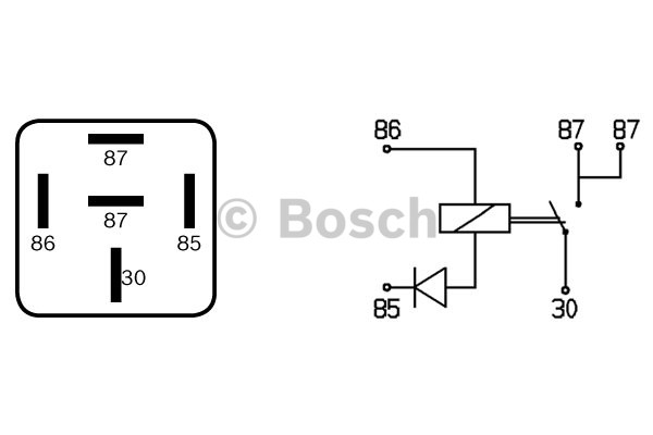
The brown relay that you posted earlier is the correct one. As can be seen with the relay removed, 2 x terminal 87 apertures at the relay plug are one above the other in a horizontal position

When switching the ignition on with the relay fitted there should be approximately 12 volts at both of the 87 terminals for a few seconds and a constant 12 volts at them both once the engine is running
Best check the above 12 volts is at those above 2 x 87 terminals before going any further
If all is good with the above relay outputs test....
Yes disconnect both Lambda sensors, find terminals or thin wires that will fit into their plug terminals but not too big as they will open the plug terminals up past their natural sprung pressure and damage them (don't let the terminals or wires touch each other). Connect a test lamp to the terminals then turn the ignition on to see if the supply and return is getting there to them during that initial few seconds switching of the relay
That probing of the wires is for kids, the person that posted it didn't give any consideration about the future damage at the sensor cables due to salt water or anything else for that matter getting at the conductors
Enjoy, have fun
Monsterlime said:
Thanks, but how do you know which relay/connector does what? Should I just unplug one and see if the fuel pump primes?
And when you talk about the long lead test lamp, do you mean unplugging a lamdba connection and then putting another wire into the holes for the white and red leads from the lambda on the loom side to see if there is supply to it or do this from the relay connector?
There are 2 relays for the engine management unplugging either of them will stop the pump so you will learn nothing from that.And when you talk about the long lead test lamp, do you mean unplugging a lamdba connection and then putting another wire into the holes for the white and red leads from the lambda on the loom side to see if there is supply to it or do this from the relay connector?
the fuel pump relay has a permanent +12v supply in at pin 30 (Purple/white) so that is your first way to identify it. Start your test by ensuring you have +12v at that pin. There should then be a pin marked 87 with a black wire and (if you have a fuel vapour canister) a white/purple wire. The black wire is the fuel pump. The other pin marked 87 (see the earlier diagram for pin positions) should have 2 wires both white/orange going to your lambda heaters. With ignition off test all the connections on the back of the relay connector with the relay plugged in. Only pin 30 should have 12v on it.
If this is the case then put your test lead on one of the pin 87 and turn on ignition. For a few seconds you should get +12. do the same for the other pin 87.
Re long test leads this is only if you don't have an assistant to turn on the ignition.
Steve
Monsterlime said:
Thank you, this is very helpful. One final question - Is the blue connector in the below image ALWAYS the fuel one? I just want to make sure I play with the right one. 

Should be but "should" can be dangerous, people get things wrong or change thingsCompare what your loom cable colours are to those in the image and diagram
The ECU Relay won't have any white, white/orange trace, white/puple trace or any other white/??????traced cables............obviously the Fuel Pump/Lambda Sensors relay will have
Here is a better diagram https://www.dropbox.com/sh/i0acxr8nwr10ow6/AACcZ2H...
Link found here https://www.pistonheads.com/gassing/topic.asp?h=0&...
Checked and found the right connector (it was blue), and tested each pin. Pin 30 did have a constant 12v, and the other 2 had 12V when the ignition was turned on and then dropped away.
Am going to make up a test lead with some circuit prototyping wiring I have around and an LED, for the lambda connections.
Am going to make up a test lead with some circuit prototyping wiring I have around and an LED, for the lambda connections.
Monsterlime said:
Checked and found the right connector (it was blue), and tested each pin. Pin 30 did have a constant 12v, and the other 2 had 12V when the ignition was turned on and then dropped away.
Am going to make up a test lead with some circuit prototyping wiring I have around and an LED, for the lambda connections.
Whatever you use to test the circuit at the Lambda sensor plugs needs to put a load on the circuit, an LED drawing so little current won't achieve thisAm going to make up a test lead with some circuit prototyping wiring I have around and an LED, for the lambda connections.
A test lamp with 21 Watt bulb will put a load on the circuit
A headlamp bulb will be better 60 Watt 5 Amps (not trying to teach Grandmother to suck eggs)
Circuits sometimes check ok without a load test on them but fail when loaded
No worries, all good learning, thank you.
One question - would leaving one lambda plugged in and then connecting the led up to the other connection put enough load on? Since both are throwing a code, its likely a problem in the wiring in the engine bay. I could easily swap it about as well, just to make sure. Or is that daft?
I definitely have some spare headlamp bulbs around I can use.
Monsterlime said:
No worries, all good learning, thank you.
One question - would leaving one lambda plugged in and then connecting the led up to the other connection put enough load on? Since both are throwing a code, its likely a problem in the wiring in the engine bay. I could easily swap it about as well, just to make sure. Or is that daft?
I definitely have some spare headlamp bulbs around I can use.
The problem with testing as above would be that the load wasn't on the Lambda Sensor circuit being testedOne question - would leaving one lambda plugged in and then connecting the led up to the other connection put enough load on? Since both are throwing a code, its likely a problem in the wiring in the engine bay. I could easily swap it about as well, just to make sure. Or is that daft?
I definitely have some spare headlamp bulbs around I can use.
Are these type of plugs in use?

If yes
Should you be able to get to the back of the terminals in the plugs, leaving the Lambda Sensors connected and testing at the rear of the terminals would do the job, a multimeter will check the voltage if using this method and a lamp load wouldn't be required
Obviously sensors with known good heater elements would be needed, otherwise perhaps no load was being applied to the circuit being tested if a sensor element was faulty
Edited by Penelope Stopit on Thursday 5th September 08:58
Yes, those are the connections. I've definitely misunderstood then, I thought both Lambda's were on the same circuit.
I'll see if I can find the second set of connections, I hadn't seem them while poking around.
My plug socks have shown up, so will hopefully have the time this weekend to do the plugs, HT leads (inc king lead), dizzy cap and rotor arm.
I know I am posting a lot of questions, but this is fun (for me). Almost as fun as actually driving the car. All the help is much appreciated!
I'll see if I can find the second set of connections, I hadn't seem them while poking around.
My plug socks have shown up, so will hopefully have the time this weekend to do the plugs, HT leads (inc king lead), dizzy cap and rotor arm.
I know I am posting a lot of questions, but this is fun (for me). Almost as fun as actually driving the car.
All the help is much appreciated!Monsterlime said:
Yes, those are the connections. I've definitely misunderstood then, I thought both Lambda's were on the same circuit.
I'll see if I can find the second set of connections, I hadn't seem them while poking around.
My plug socks have shown up, so will hopefully have the time this weekend to do the plugs, HT leads (inc king lead), dizzy cap and rotor arm.
I know I am posting a lot of questions, but this is fun (for me). Almost as fun as actually driving the car. All the help is much appreciated!
Vehicle electrical testing is much fun, it's good that you're enjoying itI'll see if I can find the second set of connections, I hadn't seem them while poking around.
My plug socks have shown up, so will hopefully have the time this weekend to do the plugs, HT leads (inc king lead), dizzy cap and rotor arm.
I know I am posting a lot of questions, but this is fun (for me). Almost as fun as actually driving the car.
All the help is much appreciated!Yes you'll find or maybe find that there is one White/Orange cable from one of the fuel pump relay terminal 87's that splits (splice) into two somewhere in the engine loom not far away from where both sensor looms enter the engine loom. Who knows, the fault may be in this area
Penelope Stopit said:
........Yes you'll find or maybe find that there is one White/Orange cable from one of the fuel pump relay terminal 87's that splits (splice) into two somewhere in the engine loom........
All the ones I have seen both the white/orange wire are in the same terminal at the relay.Steve
Steve_D said:
Penelope Stopit said:
........Yes you'll find or maybe find that there is one White/Orange cable from one of the fuel pump relay terminal 87's that splits (splice) into two somewhere in the engine loom........
All the ones I have seen both the white/orange wire are in the same terminal at the relay.Steve
Monsterlime said:
Thanks, I have new HT leads (that won't be using the extenders) and plugs to go in, but hadn't thought about touching the dizzy. Will add that to the list.
As it happens, for now, the shunting issue seems solved. I put the new amp on, made sure it had a liberal amount of thermal paste applied
I hope you get to the bottom of this soon. These issues are a bugger. As it happens, for now, the shunting issue seems solved. I put the new amp on, made sure it had a liberal amount of thermal paste applied
Edited by Monsterlime on Tuesday 27th August 12:06
Just fyi, too much thermal paste can actually cause overheating issues. You only need the thinnest scrape of paste, just enough to fill the imperfections of the surface of the amp/disti.
Good luck!

Oldred_V8S said:
I hope you get to the bottom of this soon. These issues are a bugger.
Just fyi, too much thermal paste can actually cause overheating issues. You only need the thinnest scrape of paste, just enough to fill the imperfections of the surface of the amp/disti.
Good luck!
This ^ and better to use computer CPU thermal paste than the crap not suitable for the job silicone grease often inc with a new ign module Just fyi, too much thermal paste can actually cause overheating issues. You only need the thinnest scrape of paste, just enough to fill the imperfections of the surface of the amp/disti.
Good luck!
 I have just fixed a Mitsubishi V6 with random misfire fault codes when running for long periods due to owner not cleaning module mounting plate and using thermal paste (module overheating) that was last week and all clear so far
Gassing Station | Chimaera | Top of Page | What's New | My Stuff