Speeduino install update.
Discussion


I'm getting into some basic idle tuning now with mixed success.
I've got it starting reasonably well and idling with a good AFR but if you blip the throttle it leans out horribly and the engine just wants to stall. It's like it's taking a massive gulp of air but not getting the fuel to match.
I think this is down to a lack of Acceleration Enrichment but I'm not confident I have the right settings.
I'm set up for MAP tuning but have set this on TPS controlled enrichment as I thought this might give the most rapid response to blipping the throttle.
Would the aftermarket ECU folks be able to share their settings? Pictures of what I have for this and the fuel table below.
Belle427 said:
I can check my old cars file later but are you happy the tps is calibrated and the settings such as required fuel are all correct?
Did you generate the ve table or is it a base map provided by someone?
Yep, TPS is calibrated. VE table came from a typical Rover V8 base map that was on the Canems website but to be honest I'm only really working around idle currently and I've already leaned this out a lot to get a sensible AFR. I started around 35 and had to reduce to 28 in the cells around idle speed.Did you generate the ve table or is it a base map provided by someone?
Required fuel looks good. I calculated 16m/s based on my injectors (Opel V6 Bosch) which have a flow rate of 202cc/min.
I'm not currently running an idle control valve which I don't think is helping. It revs fine if you go very slowly but if you blip hard it stutters badly, leans right out and wants to stall. It's almost as if Acceleration enrichment isn't working at all. So maybe I'm just being too conservative with the curve.
Yeah would be good to see your settings. Thanks.
Belle427 said:
Send me a message via email and I will send you my base file provided to me and a road created map, you should be able to open it just to view it but it is Megasquirt/Tunerstudio.
Mine was mapped on the road using Tps (AlphaN) as it was the choice of the tuner, it felt more responsive to me to be honest as I did try using map myself.
Its for a 400 but the settings may help you.
Thanks! mine is a 400HC so won't be far away. Just sent you a message.Mine was mapped on the road using Tps (AlphaN) as it was the choice of the tuner, it felt more responsive to me to be honest as I did try using map myself.
Its for a 400 but the settings may help you.
geordiepingu said:
If you are running without an idle control valve, have you got the ports all blanked off to stop the vacuum leak?
You will be on forever tuning AE if you are doing it by AFR. The trick is to keep richening it until it stops bogging down, then data log it to fine tune it, where you can calculate and see the lambda delay.
That said, before you tune acceleration enrichment, you should work on getting your fuelling closer. The autotune function in TunerStudio can help get the figures roughly where they want to be for the likes of fast idle etc before you fine tune the table by hand. Once you are happy that it's at a reasonable AFR in that load cell, you will find tuning acceleration enrichment a lot easier.
Another tip for setting up your fuelling, you will find it easier if you disable EGO control at first.
Yep all ports blanked off, in fact I'm pulling 30kPA at idle which I think is pretty impressive as a manifold vacuum.You will be on forever tuning AE if you are doing it by AFR. The trick is to keep richening it until it stops bogging down, then data log it to fine tune it, where you can calculate and see the lambda delay.
That said, before you tune acceleration enrichment, you should work on getting your fuelling closer. The autotune function in TunerStudio can help get the figures roughly where they want to be for the likes of fast idle etc before you fine tune the table by hand. Once you are happy that it's at a reasonable AFR in that load cell, you will find tuning acceleration enrichment a lot easier.
Another tip for setting up your fuelling, you will find it easier if you disable EGO control at first.
EGO disabled at the moment. I did think that might just confuse the issue so left it off.
Autotune does sound like the next step to be honest.
ric355 said:
A quick note to those who have MS2 and are talking about various features being discussed here (e.g. EGO control): Speeduino is not the same as MS2 (the firmware is completely different), and so stuff that works well on MS2 may not be as effective on Speedy. So just bear that in mind when discussing things.
With regards to idle MAP, I'm surprised you've got it as low as 30kpa. Mine idles at 45-50kpa although I'm idling it relatively lean when hot as I don't like the smell of a rich idle.
For the relay pulse generator, I put mine into the original tach wire on the original connector and it worked fine (white Caerbont tacho). You obviously need to extract the coil from the relay entirely for your final solution; there should be no mechanical parts left.
For Accel enrichment, I think the graph you've got is not adding any fuel. In fact I think it is taking fuel out. This is because in multiply mode the numbers are percentages so a value of, say, 85 means "take 85% of the pulse width" rather than "turn the pulse with up to 185%". You either need to alter the graph or change the type to Adder instead. You can verify if I'm correct by taking a data log and looking at the pulsewidth when you pump the throttle. I'm running an earlier version of firmware at the moment which doesn't have the PW Multiplier option, so I can't check this for you. Incidentally, learning to read the logs is important - it will guide you a lot.
Autotune is not very good for idle tuning - stay away from it in that region (fast idle no problem).
The closed loop stepper idle control works but again it is not very good for maintaining the idle speed because the stepper motor isn't fast enough for the PID control loop, so stick to open loop idle control when you get the stepper running, or update to a bosch style PWM based valve. I would recommend getting the stepper working sooner rather than later otherwise you'll have to retune certain things once you've added it.
Req_fuel looks fine at 16ms. Mine is a bit higher (20ms IIRC) but I'm still on the original 180cc injectors and a 4.5 engine.
For accel enrichment you want the taper to start a bit higher - I have mine tapering from 3000 to 4000rpm. My pulse time is set to 130ms for what it's worth, but the amount you add/multiply drastically affects the appropriate value here so you should do your own thing.
You will get best response from the 'instantaneous' MAP setting. It seems to work fine with the large plenum on the RV8. But you need to make sure you can run without any filtering and still have good signal. I have been wanting to try TPS for load at some point to see if it runs better but it's just a big job to change it over and I can't motivate myself to do it. Theoretically MAP is a better estimate of load under certain conditions but I don't want to start a debate about it.
Brilliant!! Thanks ric355. This is really useful. I think you may have found the reason why the engine dies when revving. Will change the Accel enrich settings and set up a log this time. 2 wire PWM valve on the way so best get this installed quick before I go too much further.With regards to idle MAP, I'm surprised you've got it as low as 30kpa. Mine idles at 45-50kpa although I'm idling it relatively lean when hot as I don't like the smell of a rich idle.
For the relay pulse generator, I put mine into the original tach wire on the original connector and it worked fine (white Caerbont tacho). You obviously need to extract the coil from the relay entirely for your final solution; there should be no mechanical parts left.
For Accel enrichment, I think the graph you've got is not adding any fuel. In fact I think it is taking fuel out. This is because in multiply mode the numbers are percentages so a value of, say, 85 means "take 85% of the pulse width" rather than "turn the pulse with up to 185%". You either need to alter the graph or change the type to Adder instead. You can verify if I'm correct by taking a data log and looking at the pulsewidth when you pump the throttle. I'm running an earlier version of firmware at the moment which doesn't have the PW Multiplier option, so I can't check this for you. Incidentally, learning to read the logs is important - it will guide you a lot.
Autotune is not very good for idle tuning - stay away from it in that region (fast idle no problem).
The closed loop stepper idle control works but again it is not very good for maintaining the idle speed because the stepper motor isn't fast enough for the PID control loop, so stick to open loop idle control when you get the stepper running, or update to a bosch style PWM based valve. I would recommend getting the stepper working sooner rather than later otherwise you'll have to retune certain things once you've added it.
Req_fuel looks fine at 16ms. Mine is a bit higher (20ms IIRC) but I'm still on the original 180cc injectors and a 4.5 engine.
For accel enrichment you want the taper to start a bit higher - I have mine tapering from 3000 to 4000rpm. My pulse time is set to 130ms for what it's worth, but the amount you add/multiply drastically affects the appropriate value here so you should do your own thing.
You will get best response from the 'instantaneous' MAP setting. It seems to work fine with the large plenum on the RV8. But you need to make sure you can run without any filtering and still have good signal. I have been wanting to try TPS for load at some point to see if it runs better but it's just a big job to change it over and I can't motivate myself to do it. Theoretically MAP is a better estimate of load under certain conditions but I don't want to start a debate about it.
OK, very frustrating day.
I got the Acceleration enrichment working it was just as you said ric355 the curve was working upside down.
It was revving beautifully from idle...... then something happened.
Suddenly the AFR shot to 21. Running dreadfully lean and won't idle at all and will barely start. I thought I'd run out of fuel but dipped the tank and still have 5 inches of fuel left. (Gauge isn't reliable under 1/4)
I just can't do anything with it....All the gauges are still working correctly, Trigger wheel working OK etc. But it's now suddenly massively under-fuelling despite no changes to the VE table.
Totally confused.
Edited by Fenderer on Friday 13th May 18:04
Looks like there is an issue withe supply to the fuel pump as I've got no voltage at all at the terminals of the pump and it now won't prime.
Pin 87 of the fuel pump relay is only showing 7.3v when the pump is trying to prime, so either the ECU isn't grounding the fuel pin correctly or there's a massive voltage drop to the pump.
Pin 87 of the fuel pump relay is only showing 7.3v when the pump is trying to prime, so either the ECU isn't grounding the fuel pin correctly or there's a massive voltage drop to the pump.
ric355 said:
I'm not clear how much of the original loom you still have. For my installation I have the original loom still in tact right down to the OEM 14CUX connector, and thus I had to engineer a way to ensure that the OEM main relay is turned on when the ignition key is activated. Without that, you get no supply to the fuel pump relay.
The answer to that is there's not much left of the original loom into the engine bay. I've ripped out all the old relays and connectors and most of the OE wiring. I've got a totally separate sub-fusebox now located under the dash, fed upstream of Fuse 12 in the main fusebox. One relay controls coil packs and fuel pump and the other looks after injectors and the ECU. Basically the main relay goes live when the switched ignition goes on. The fuel pump and coil pack relay goes live when the Speeduino grounds pin 85 i.e. the fuel pump run signal. The odd thing is I was only get +8v or thereabouts when looking at the voltage measured between the Speeduino fuel pump run pin 16 on the board and the voltage at supply pin 87 of the fuel pump relay.
My initial thought was that the pump wiring was so knackered it was drawing down the voltage to this level due to crazy resistance but I pulled the fuse and it was still there. If I measured between pin 85 of the main relay which has a proper ground to the chassis and the same pin 87 I get the full 12.5v battery voltage. So this would leave me to conclude that under fuel priming (the configurable 4 or sec routine to pressurise the fuel rail) the Speeduino is not actually fully grounding pin 16 which sounds daft so left me confused. Either way it was enough to trigger the relay and supply the pump so wasn't the problem just another weird anomaly.
I tried to put that aside as it was pretty clear the pump wasn't running. I disconnected the terminals switched on the ignition and got full battery voltage at the pump terminals, but pump wasn't running, so basically the pump died. Got the pump off and tested straight across a battery and it wouldn't there either so it must have been slowly dying , caused the lean out and then just gave up.
New pump coming next week and will start again.
Edited by Fenderer on Sunday 15th May 20:43
Edited by Fenderer on Sunday 15th May 20:44
lancepar said:
If you need to test the pump.
Run a 12v pos and neg supply to it with the OE wiring disconnected. even if you run it backwards it will do no harm and if it's blocked it should clear it anyway.

Thanks, yes exactly what I did in the end and found pump is knackered which explains a lot.Run a 12v pos and neg supply to it with the OE wiring disconnected. even if you run it backwards it will do no harm and if it's blocked it should clear it anyway.
I'm using 0.4.3d, the last one before SMT which has a ULN2003 on board and proto has been removed.
Either way the fuel pump output is only grounding pin 85 of the main relay so shouldn't be supplying any current other than the 130mA or so to power the relay coil?
This is assuming I haven't made the completely wrong assumption about how that pin works. My understanding is that the Speeduino grounds that pin (pin 16 on the IDC) to run the pump.
Edited by Fenderer on Monday 16th May 15:24
ric355 said:
You're correct about the grounding. All of the speeduino outputs are grounds.
On boards without a ULN, there are a set of proto area pins connected directly to the arduino mega. The intent with these is that you put a circuit in the proto area (most often just a ULN) and the output of that circuit connects to one or more IDC pins that are physically next to the proto pins. It's possible to simply bridge from the proto area to the relevant IDC pin with just a wire but this effectively connects whatever is on the IDC pin directly to the arduino's digital output. In the case of a relay that would mean it would need to sink the relay coil current through the arduino, which is too much for it and would immediately blow the digital output pin.
If your output is driven by the ULN you're fine.
The medium current outputs have mosfets on them hence why it's common to use those on slightly earlier boards to control relays and the like.
Great thanks that's reassuring. Going to do some more testing and make sure I haven't run myself around in circles with voltage measurements.On boards without a ULN, there are a set of proto area pins connected directly to the arduino mega. The intent with these is that you put a circuit in the proto area (most often just a ULN) and the output of that circuit connects to one or more IDC pins that are physically next to the proto pins. It's possible to simply bridge from the proto area to the relevant IDC pin with just a wire but this effectively connects whatever is on the IDC pin directly to the arduino's digital output. In the case of a relay that would mean it would need to sink the relay coil current through the arduino, which is too much for it and would immediately blow the digital output pin.
If your output is driven by the ULN you're fine.
The medium current outputs have mosfets on them hence why it's common to use those on slightly earlier boards to control relays and the like.
OK just checked again and it's pretty confusing.
With ignition on - Testing on the Fuel Pump Relay.
I'm getting:
8v between pin 86 and pin 85 - Pin 85 is connected to Speeduino - Pin 16 on the board IDC
12.6 v between pin 86 and known ground.
This suggests the Speeduino isn't grounding the fuel run pin with ignition on.
To verify - Voltage between known Ground and Speeduino - Pin 16 on the board IDC is 4.5v.
This proves the pin isn't grounded.
I don't understand why... With ignition on, the fuel pump should prime, so it should ground the pin for 4 seconds or so set in the software. Maybe it will 8v is actually enough to trigger the relay so the fuel pump will try to run anyway even though it's not getting the right trigger voltage.
Am I missing something in how the Speeduino operates?
Edited by Fenderer on Monday 16th May 18:24
ric355 said:
As a suggestion to help with investigations, you could try moving the fuel pump output to either BOOST or VVC. This removes the ULN and replaces it with a MOSFET so it puts you on a different circuit. You will need to set the fuel pump pin in the tune, and make sure no other setting in the tune is using that same pin otherwise you'll get odd results.
That would at least help to prove whether there is an issue with the ULN on your board or whether it's something else.
Regards the grounding, the way I check this is to measure continuity between the output pin on the IDC and the ECU ground using a meter that beeps. Or look for zero ohms if you don't have a beep feature. If you don't get continuity at the IDC you can move back to the arduino's output pin and check there; however on the arduino pin it should go high when the pump is on (as it's driving another device to get the low) so you'll need to read voltage there or continuity against +5v.
There is one other detail you could check - make sure you are getting a decent battery voltage reading in TunerStudio i.e. 12v+. The firmware has some logic in it that detects whether the ignition key has been turned on by checking that the main battery voltage is > 7v. When it sees that it does a fuel pump prime. It also does it if the voltage is < 5.5v - this detects a USB connection. But if somewhere in between, it does nothing. The reason this exists is that powering the board by USB in order to use tunerstudio turns on the arduino, so if you plug in the USB first, then turn on the ignition key some seconds later, the fuel pump prime would be missed without detecting the voltage change.
Thanks again. That would at least help to prove whether there is an issue with the ULN on your board or whether it's something else.
Regards the grounding, the way I check this is to measure continuity between the output pin on the IDC and the ECU ground using a meter that beeps. Or look for zero ohms if you don't have a beep feature. If you don't get continuity at the IDC you can move back to the arduino's output pin and check there; however on the arduino pin it should go high when the pump is on (as it's driving another device to get the low) so you'll need to read voltage there or continuity against +5v.
There is one other detail you could check - make sure you are getting a decent battery voltage reading in TunerStudio i.e. 12v+. The firmware has some logic in it that detects whether the ignition key has been turned on by checking that the main battery voltage is > 7v. When it sees that it does a fuel pump prime. It also does it if the voltage is < 5.5v - this detects a USB connection. But if somewhere in between, it does nothing. The reason this exists is that powering the board by USB in order to use tunerstudio turns on the arduino, so if you plug in the USB first, then turn on the ignition key some seconds later, the fuel pump prime would be missed without detecting the voltage change.
OK I've now taken the ECU back out of the car and I'm just testing on the bench to go back to first principles and make sure both the Arduino and ULN are doing the right things. Sadly still getting really confusing results.
Firstly it won't prime under USB power at all - I presume this is because of the reason you said above as the firmware is detecting it's running on USB bus power (5v) and need not prime. I also thought it wouldn't prime anyway as the Speeduino board isn't powered under bus power?.
Tests:
1 - Arduino outputs +5v on pin 45 for the length of the priming period - Good news - this means the Arduino is working and initiating the fuel prime.
2 - Checking for continuity between ECU ground and PIN16 on the IDC. Get 709 ohms before power up, then 448 ohms for the length of the prime period, then goes open circuit. Looks like I'm getting a prime signal but why isn't is 0 ohms or thereabouts for the length of the prime?
3 - Changed Fuel output from 'board default' to Arduino Pin 7 (Boost) - No prime at all Just goes open circuit as soon as it powers up.
So I know Arduino is working but it still doesn't look I'm getting a proper ground signal from the ULN. Do we know if there is any other circuitry apart from the ULN involved in converting the logic +5v signal from Arduino to the continuity signal on Pin16. Maybe it's damaged from the fuel pump fail but I can't see how as it's not physically connected to the Speeduino.
All really confusing.
Edited by Fenderer on Tuesday 17th May 18:15
Polly Grigora said:
Would you happen to know what the voltage was between B+ and Fuel pump relay terminal 85 when the fuel pump primed as commented above?
Why I ask is, am wondering if the output from Pin 16 was ever what it should have been or was there a low output fault in the board from the very beginning
I can't remember if I measured that. There is a very good chance the output from Pin16 has always been wrong though I've never been happy with the relay trigger voltage and it seems to point back to the ECU not grounding PIN16 correctly.
ric355 said:
Most functions on the speedy board require it to be properly powered via the 12v feed to operate properly. This is mostly the MOSFET driven stuff. You should always power it via 12v when testing anything otherwise you're in unknown territory.
Regarding boost, I have just been looking at the code here for another user, and you must make sure that the boost configuration in TS is moved to a different pin if you are using it for FP. It is likely disabled and set to 'board default' -- but this is pin 7 so you have a clash where one pin is set for 2 functions. The code doesn't discriminate whether stuff is enabled or not during initialisation so it will likely enable the boost pin as an output pin and turn it off during init. Enable boost, change the pin to something not used anywhere else, burn the tune, disable the function, burn the tune again. This just makes sure the pin is burned and not only the enabled setting.
I would expect a lot less than 448 ohms when the FP pin is grounded. Something definitely not right there. Check all your solder joints in the circuit involving that pin. I suggest resoldering them regardless of what they look like, but doing the boost pin config changes worthwhile and retesting too.
Edited by ric355 on Wednesday 18th May 11:34
Yeah as ric355 says, you do need a pull up resistor. But it's really easy to set a voltage divider network up on a breadboard and test before installing it. I'm using the E36 hall effect sensor but wanted to make sure it was doing the right things before going to the effort of making it part of the wiring loom.
I just find it easier to understand what is going on testing on the bench, and then install it once I know how it works.
I've now found that my ULN2003 was indeed blown on the fuel pump input through bench testing the chip in isolation. New ULN's have arrived and so has the new fuel pump and filter so hopefully will get it all back up and running this weekend. I will do some relay testing first on the bench though as I'm still not convinced that that I'm getting the right pull in voltage on the relay coil.
Polly Grigora said:
Don't understand why the coils have been supplied from the fuel pump relay
The coils should be supplied directly from the ignition switch switched supply or from an ignition switch controlled relay, Whatever the method used, the ignition coils supply shouldn't be connected into another circuits relay
There is no reason to supply the ignition coils from a timed relay such as the fuel pump is
Well you can argue that with the hundreds of Megasquirt folk that do it this way. Either way, it's not the cause of my issues.The coils should be supplied directly from the ignition switch switched supply or from an ignition switch controlled relay, Whatever the method used, the ignition coils supply shouldn't be connected into another circuits relay
There is no reason to supply the ignition coils from a timed relay such as the fuel pump is

Quick update.
- New fuel pump installed -
- New ULN2003 installed -
- Fuel pump primes again YAY! , now getting correct voltage across relay...
Ran great for 5 mins then went horribly lean AFR, too lean for the gauge and won't idle. Unbelievably frustrating!
So etiher I'm still not getting enough fuel or maybe there's a huge air leak...
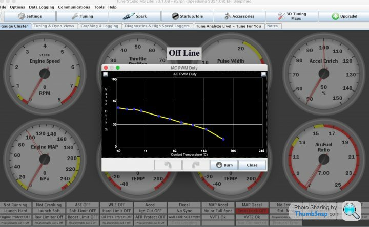
I'm not convinced I'm understanding how the PWM air valve should be working. Should it be open maintaining idle speed? But how does this affect the mixture. If there's a load of extra air from the valve and no extra fuel then surely it will run lean?
PWM duty below.
- New fuel pump installed -
- New ULN2003 installed -
- Fuel pump primes again YAY! , now getting correct voltage across relay...
Ran great for 5 mins then went horribly lean AFR, too lean for the gauge and won't idle. Unbelievably frustrating!
So etiher I'm still not getting enough fuel or maybe there's a huge air leak...
I'm not convinced I'm understanding how the PWM air valve should be working. Should it be open maintaining idle speed? But how does this affect the mixture. If there's a load of extra air from the valve and no extra fuel then surely it will run lean?
PWM duty below.
Belle427 said:
Are you using the standard stepper motor?
The warm up enrichment tool in tune analyze is pretty good, have you run this?
It’s all a bit of a balancing act and takes a while to get right.
No I junked it mainly as it was doubtful that Speeduino would be able to control it so I went with a 2 wire Bosch air valve.The warm up enrichment tool in tune analyze is pretty good, have you run this?
It’s all a bit of a balancing act and takes a while to get right.
But to be honest I have no idea what I'm doing with it. I can't really get my head around how Speeduino is adjusting for the increased air. There doesn't seem to be any table that maps PWM duty with additional fuel.
If I turn the valve off i,e shut it won't idle at all as the base idle speed is too low so it obviously needs some additional air even when up to coolant temp.
It feels like a fundamental lack of fuelling for some reason, but I have a brand new pump, new filter, injector duties look sensible and it's using the same VE values as when it was originally idling OK before this happened.
I don't think it's an WUE issue as it was fully up to temp and not using the curve and still not idling, running lean,
I don't really know where to go with it to be honest.
Gassing Station | Chimaera | Top of Page | What's New | My Stuff