Instructions to change fuel maps on 14CUX Griffith, Chimaera
Discussion


Mark,
Its brilliant you’re keen to perfect the idle control as its a common cause of complaint and you’re making impressive progress with the assembler code. Dan always said the idle control code is the most complicated part of the code as you’ve discovered.
Normally the stepper is held fully open before cranking up to the temperature stored at prom offset 17E (87 deg C) which is inside the cranking stepper control table at offset 17B to 195 and the stepper is then controllable before cranking above 87 deg c.
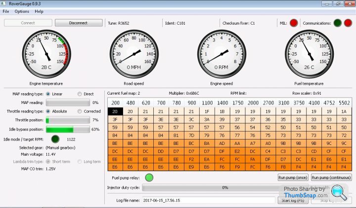
A few years ago I changing “cmpb $C17E” to “cmpb $C182” in the code below which appears in the RoverGauge screen shot to allow stepper control before cranking down to –14 degrees C as required and even starts ok, BUT sadly before cranking you can hear the stepper motor buzzing which must mean the stepper is repeatedly pulled fully open again elsewhere in the code. We really need to flow diagram idleControl.asm, stepperMtr2.asm and coolant.asm to understand the bigger picture, I've tried several times and end up lost in the maze of code.
It make sense what you are trying to do but unfortunately raising the base idle without stepper control before cranking is exacerbating your cranking issue and also creates other issues like raising the coasting idle which can all be re-adjusted for. This is because all the stepper control code and data tables are written for a larger difference between the base idle and target idle. Mark Blitz normally recommends setting the base idle as low as possible i.e. just before the engine stalls without any extra air via the stepper and the stepper should normally be between 20% to 30% when idling hot.
As a result I’ve been lowering the base idle as much as possible as it also reduces your initial cranking idle issue and coasting idle. Eventually lowering the base idle too much then creates a hot cranking idle issue which I’ve successfully over come with my hot start fix.
Two heads are better than one (I don’t mean cylinder heads) and investigating both avenues is a good way to learn and help find the best solution to improve our cars.
Its brilliant you’re keen to perfect the idle control as its a common cause of complaint and you’re making impressive progress with the assembler code. Dan always said the idle control code is the most complicated part of the code as you’ve discovered.
Normally the stepper is held fully open before cranking up to the temperature stored at prom offset 17E (87 deg C) which is inside the cranking stepper control table at offset 17B to 195 and the stepper is then controllable before cranking above 87 deg c.
A few years ago I changing “cmpb $C17E” to “cmpb $C182” in the code below which appears in the RoverGauge screen shot to allow stepper control before cranking down to –14 degrees C as required and even starts ok, BUT sadly before cranking you can hear the stepper motor buzzing which must mean the stepper is repeatedly pulled fully open again elsewhere in the code. We really need to flow diagram idleControl.asm, stepperMtr2.asm and coolant.asm to understand the bigger picture, I've tried several times and end up lost in the maze of code.
;Land Rover 3.9: R3652, R3383 & all TVR 2967 4L - 5L except 430BVCat
;Degrees C          130  114   94   87   55   50   25 -14  -21
C17B            DB  $00, $0B, $1C, $23, $48, $51, $88, $E4, $F2 ; Coolant temperature (Compared one ahead)
C184            DB  $78, $78, $A0, $A0, $88, $85, $72, $50, $1E ; Column starting Y Axis
C18D            DB  $00, $97, $00, $2A, $15, $16, $18, $E5, $08 ; Rate of increase/decrease to right (00=flat)

idleControl.asm
                ldaa        $0085               ; bits value
                bita        #$04                ; test 0085.2 (set and tested in IS routine)
                bne         .LD690              ; rtn if 0085.2 is set
                bita        #$80                ; test 0085.7 (may indicate low eng RPM)
                beq         .LD691              ; branch ahead if 0085.7 is clr (engine running)
                ldab        ignPeriod
                cmpb        $C16F               ; for 3360 code, value is $53 (353 RPM)
                bcs         .LD691              ; branch ahead & continue if engine PW is LT $5300 (RPM > 353)
                ldab        coolantTempCount
                cmpb        $C17E               ; inside coolant temp table (value is $23)
                bcs         .LD691              ; branch ahead & continue if cool temp is LT $23 (hotter than)

.LD690          rts
eisdielenbiker said:
The effect at 64% so far counts up to 200 rpm only, I will lower this little mor maybe 45% for the summer. You could possibly use the standard coolant idle tab values to get a simple temperatur dependency...if required. In the end you only had to preselect the coolant tab stepper count a little ahead to its appliaction in idlecontrol.asm I will proof the necessity of this further step in November.
Base idle screw is set 700 rpm to keep stepper valve influence at minimum on idle , ECU base software idle is 750 when engine is warm. The first might be causing a higher effect of a 100% open valve immediately after cranking...
Mark,Base idle screw is set 700 rpm to keep stepper valve influence at minimum on idle , ECU base software idle is 750 when engine is warm. The first might be causing a higher effect of a 100% open valve immediately after cranking...
It make sense what you are trying to do but unfortunately raising the base idle without stepper control before cranking is exacerbating your cranking issue and also creates other issues like raising the coasting idle which can all be re-adjusted for. This is because all the stepper control code and data tables are written for a larger difference between the base idle and target idle. Mark Blitz normally recommends setting the base idle as low as possible i.e. just before the engine stalls without any extra air via the stepper and the stepper should normally be between 20% to 30% when idling hot.
As a result I’ve been lowering the base idle as much as possible as it also reduces your initial cranking idle issue and coasting idle. Eventually lowering the base idle too much then creates a hot cranking idle issue which I’ve successfully over come with my hot start fix.
Two heads are better than one (I don’t mean cylinder heads) and investigating both avenues is a good way to learn and help find the best solution to improve our cars.
OR
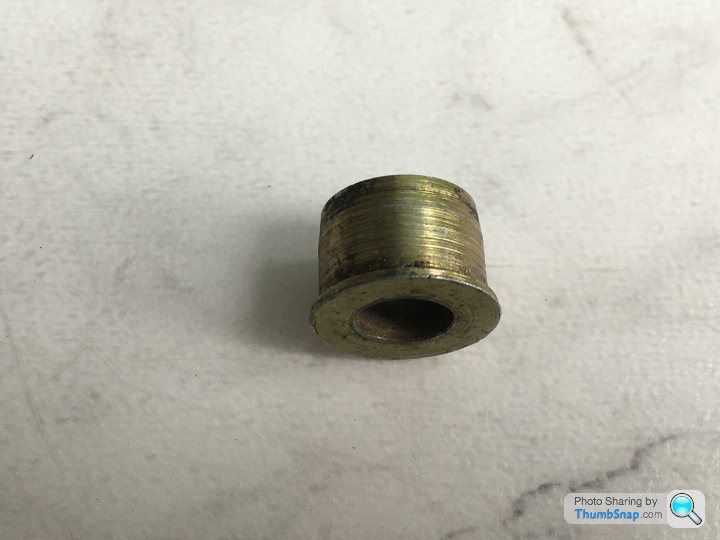
you could cheat with one of these in the stepper hose or add some washers to the stepper motor plunger to limit the fully open position, but where's the fun in that !!!Steve,
you are so right about the pitfalls of having too high a base idle. I magically ended up at a StepperMtrSave-Value of 8E although starting at a convenient initial CoastingIdleHoldUp value of 78. I.e. the CoastingIdle was getting lower in the end. This required another patch in a too-lean-code section to not adjust the stepper battery backed up ram location at all. This is for sure no PROM for everyones use because you lose a few of adaptive 14CUX functions to handle and adapt to mechanical system detoriation of any kind. Not very satisfying but educational. However I will give it a try and set up my 2nd EPROM for now.
It has shown that of my cylinder banks differ significantly in fuel supply. I will have to investigate this mechanically.
With long term trims disabled a rather perfect set up map5 on odd bank gives +100 on odd and -100 long term trim on even cylinders if you chose a medium fueling value between both banks. If you settle on the primary odd bank fueling values you end up 0% odd and minus 100% even long term trim.I guess that is usual behaviour if you dont allow the trims to be applied. AFR from left bank to right bank differs 0.5 at least overall. I will take a look into the plenum and check/replace the injectors. New small band lambdas are also required.
I admit that I have to study Dans marvellous 14CUX flow charts a little more.
Mark
IgnitionOn Steper set to only 45% and additionaly setting CrankingIDleeOffs from $1E to $00 gave this cold start:
roadSpeed engineSpeed waterTemp fuelTemp throttlePos mafPercentage idleBypassPos
0 0 20 -17 0,0459 0 0,450
0 115 20 -17 0,0459 0 0,450
0 120 20 -17 0,0459 0 0,450
0 124 20 -17 0,0459 0 0,450
0 137 20 -17 0,0459 0 0,450
0 140 20 -17 0,0459 0 0,450
0 143 20 -17 0,0459 0 0,450
0 147 20 -17 0,0459 0 0,450
0 148 20 -17 0,0459 0 0,450
0 152 20 -17 0,0459 0 0,450
0 188 20 -17 0,0459 0 0,444
0 732 20 -17 0,0469 0 0,389
0 1350 20 -17 0,0469 0 0,389
0 1694 20 -17 0,0469 0 0,389
0 1698 20 -17 0,0469 0 0,389
0 1547 20 -17 0,0469 0 0,389
0 1462 20 -17 0,0469 0 0,389
0 1394 20 -17 0,0469 0 0,389
0 1344 20 -17 0,0469 0 0,389
0 1179 20 -17 0,0469 0 0,389
0 1170 20 -17 0,0469 0 0,389
0 1082 20 -17 0,0469 0 0,389
0 987 20 -17 0,0469 0 0,389
0 963 20 -17 0,0469 0 0,389
There is no obvious nor recorded rattling if you modify the preselected SteeprMtrCount at the end of MainLoop.asm.
I know that noise as I had it from a faulty EPROM once.
Is there any really old tune around before R2967 to have a look at ?
Edited by eisdielenbiker on Friday 16th June 16:15
HI Clever Folks,
After a long absence I'm ready to get back to a bit of ECU work having had all my tinker time taken up with unrelated issues. I have finally got a wideband O2 sensor installed (TechEdge 2J9) which can display and log O2 and a few other inputs digitally. I thought I was ready to start tuning however I have a couple more gremlins to expel first. My question is about the carbon canister purge valve logic.
I have recently started getting the MIL light come on with fault code 88 (Purge valve leak). I realise that conventional wisdom says bin the canister and Dan has expressed that it doesn't look like the code should work anyway, but I'd prefer to keep most of the original equipment working as intended. Does anyone know what condition the ECU detects to flag this error? If I do decide to lose the canister, does anyone know what to do to prevent the ECU throwing this fault?
Needless to say I haven't even got around to checking the pipes and electrcal connections - mainly because of the difficulty accessing the canister.
Griffian said:
HI Clever Folks,
After a long absence I'm ready to get back to a bit of ECU work having had all my tinker time taken up with unrelated issues. I have finally got a wideband O2 sensor installed (TechEdge 2J9) which can display and log O2 and a few other inputs digitally. I thought I was ready to start tuning however I have a couple more gremlins to expel first. My question is about the carbon canister purge valve logic.
I have recently started getting the MIL light come on with fault code 88 (Purge valve leak). I realise that conventional wisdom says bin the canister and Dan has expressed that it doesn't look like the code should work anyway, but I'd prefer to keep most of the original equipment working as intended. Does anyone know what condition the ECU detects to flag this error? If I do decide to lose the canister, does anyone know what to do to prevent the ECU throwing this fault?
Needless to say I haven't even got around to checking the pipes and electrcal connections - mainly because of the difficulty accessing the canister.
Griffian, good to see you're back.After a long absence I'm ready to get back to a bit of ECU work having had all my tinker time taken up with unrelated issues. I have finally got a wideband O2 sensor installed (TechEdge 2J9) which can display and log O2 and a few other inputs digitally. I thought I was ready to start tuning however I have a couple more gremlins to expel first. My question is about the carbon canister purge valve logic.
I have recently started getting the MIL light come on with fault code 88 (Purge valve leak). I realise that conventional wisdom says bin the canister and Dan has expressed that it doesn't look like the code should work anyway, but I'd prefer to keep most of the original equipment working as intended. Does anyone know what condition the ECU detects to flag this error? If I do decide to lose the canister, does anyone know what to do to prevent the ECU throwing this fault?
Needless to say I haven't even got around to checking the pipes and electrcal connections - mainly because of the difficulty accessing the canister.
The short-form answer to your Fault Code 88 question is as follows: A variable secondaryLambdaR value representing the efficacy of purging is used as a reference in the Purge Valve error check, see below. Once each purge valve active countdown has completed the resultant secondaryLambdaR is stored and also copied to purgeValveValue. Upon the next purge sequence (timed in as an interrupt) the previously copied purgeValveValue value is compared with the new secondaryLambdaR, if not within the expected range fault code 88 is set. I'm also pretty sure that this 'not in range' condition has to occur for a predefined number of purge valve interrupt counts (as represented in a purgeValveFailDelay value) and this in turn is controlled by the state of the X00DD.7 'purge value in error' status flag.
.LEEF3          bita        #$80                ; test X00DD.7
                bne         .LEF05              ; branch ahead if bit is set

                oraa        #$80                ; set X00DD.7
                staa        $00DD               ; store it
                ldab        #$FF                ; load B with $FF
                stab        purgeValveCounter   ; reset local counter to $FF
                ldab        secondaryLambdaR    ; load right bank, battery backed value X0040 (MSB only)
                stab        purgeValveValue     ; and store it as 'purgeValveValue'

.LEF03          bra         .LEF25              ; branch down

                                                ; only jump is from LEEF3(5) above, X00DD is in A
.LEF05          ldab        secondaryLambdaR    ; load right bank, battery backed value X0040 (MSB only)
                subb        purgeValveValue     ; subtract 'purgeValveValue'
                addb        $C22F               ; this data value is in the range of 1 to 3
                cmpb        $C230               ; this data value is in the range of 2 to 6
                bhi         .LEF17              ; branch ahead if B result is higher

                ldab        faultBits_4A
                orab        #$80                ; <-- Set Fault Code 88 (Purge Valve Fault)
                stab        faultBits_4A
Edited by davep on Monday 10th July 13:24
That's the short form? Thank you.
If I understand, the fault is triggered when opening the valve gives no change to the effective fuel mix. Therefore it should mean either the valve really has failed to open or there is some blockage in the pipework?
Of course the valve failing to open could be electrical problem too so I guess I've still got to get at it to do anything.
Thank you.If I understand, the fault is triggered when opening the valve gives no change to the effective fuel mix. Therefore it should mean either the valve really has failed to open or there is some blockage in the pipework?
Of course the valve failing to open could be electrical problem too so I guess I've still got to get at it to do anything.
Griffian said:
That's the short form? Thank you.
If I understand, the fault is triggered when opening the valve gives no change to the effective fuel mix. Therefore it should mean either the valve really has failed to open or there is some blockage in the pipework?
Of course the valve failing to open could be electrical problem too so I guess I've still got to get at it to do anything.
From a similar discussion on p.56: Thank you.If I understand, the fault is triggered when opening the valve gives no change to the effective fuel mix. Therefore it should mean either the valve really has failed to open or there is some blockage in the pipework?
Of course the valve failing to open could be electrical problem too so I guess I've still got to get at it to do anything.
Dan, the purge feedback element is realised by HO2S monitoring (secondaryLambda) and a lot of assumption, isn't it? Where at up to 1720 RPM (start and warming up) the canister is vented regularly with short pulses, subsequently with engine up to temperature and fuel mixture running a tad lean now's a good time to vent the carbon canister, continue until there's no change in HO2S sensor lean activity and purge valve open so now's the time to stop venting and close the valve. Well that's my theory anyways.
So, theoretically, a fault condition arises when, over a predefined period, HO2S levels resulting from exhaust gas monitoring indicate running lean and the valve is set for open but there's no change towards 'richness' as expected.
Evidently, 14CUX's attempts at OBD were (rapidly) developed to appease US Emissions Controls (hence locked tune resistor and always Closed Loop map), and the detection processes for the fault codes reflect this, basically it was Lucas/LR saying "It's all done (somehow) in the software, guv!"
Just occurred to me, you mention a wideband sensor have you removed the original narrowband Lambda sensors? If not it might be worth making sure that your original Lambda probes are in good working order, especially the right bank one.
Edited by davep on Thursday 13th July 08:36

Heads Up!
RS-V8 RoverGauge Android is now licensed as GNU:
https://www.pistonheads.com/gassing/topic.asp?h=0&...
Big thumbs up to aide.
RS-V8 RoverGauge Android is now licensed as GNU:
https://www.pistonheads.com/gassing/topic.asp?h=0&...
Big thumbs up to aide.
Hi guys !
After a long period of work where I couln't play with the 14CUX of my Range Rover, I finally took some time to get more into it.
Steve sent me an eprom with modification made to use the GEMS stepper motor with 200 steps instead of 180 for the 14CUX one. Thank you Steve ! It solved the struggling stepper motor issues.
I made a few different eprom to test different settings. I have questions about how the fuelling shut off work for the Land Rover eproms, and I tried to understand things from the ASM files but did not manage to.
In the ThrottlePot asm files, on the description there is what I want to understand and use, the injector fuel shut off on the deceleration.
I have this injector shut off around 1700-1800rpm when using the cat map 5, no matter what the engine temperature is, but when I am using the non cat map 2, I don't have this shut off unless the engine is relatively hot (~90°C). I tried to find out from the asm files how this work for cat or non cat map but didn't find what I wanted.
I would like to be able to have this shut off with the non at map 2 working as if I was using the cat map 5, because using the cat map 5 my car is running to lean.
Does anyone have any useful information that I am missing about that ?
Does the non-cat map have a temperature to reach before allowing this shut off, in this case can I lower this temperature as I am using a 78°C thermostat ?
Or does the non cat map do not have this shut off ?
Engine braking is very important for my use of the car, towing a boat downhill without engine brake is not very cool...
Cheers
After a long period of work where I couln't play with the 14CUX of my Range Rover, I finally took some time to get more into it.
Steve sent me an eprom with modification made to use the GEMS stepper motor with 200 steps instead of 180 for the 14CUX one. Thank you Steve !
It solved the struggling stepper motor issues.I made a few different eprom to test different settings. I have questions about how the fuelling shut off work for the Land Rover eproms, and I tried to understand things from the ASM files but did not manage to.
In the ThrottlePot asm files, on the description there is what I want to understand and use, the injector fuel shut off on the deceleration.
I have this injector shut off around 1700-1800rpm when using the cat map 5, no matter what the engine temperature is, but when I am using the non cat map 2, I don't have this shut off unless the engine is relatively hot (~90°C). I tried to find out from the asm files how this work for cat or non cat map but didn't find what I wanted.
I would like to be able to have this shut off with the non at map 2 working as if I was using the cat map 5, because using the cat map 5 my car is running to lean.
Does anyone have any useful information that I am missing about that ?
Does the non-cat map have a temperature to reach before allowing this shut off, in this case can I lower this temperature as I am using a 78°C thermostat ?
Or does the non cat map do not have this shut off ?
Engine braking is very important for my use of the car, towing a boat downhill without engine brake is not very cool...
Cheers
Michael (Tahiti)
Its good to hear from you and to know the GEMS stepper motor code mod worked, thanks. Are you still running the standard GEMs throttle pot with the 14CUX?
There are two temperature thresholds at the very end of each fuel map and one of them might be what you are looking for as they allow different temperature thresholds for each map. Try copying both temperature threshold from map 5 to your map 2 plus you could also try copying the very last byte in map 5 as I think it also has something to do with overrun. I haven’t had cause to experiment with these last four parameters in each map except the ‘full load fuel gain’ which MPO and myself have both proved works. It would be great to tick off these last few parameters in each map.
As you know the overrun fuel cut kicks in when the overrun starts above the RPM set at prom offset 137 & offset 137 definitely works for map 2 and 5. I think prom offset 138 & 139 are the low RPM points when the injectors are reinstated & offset 13B contains the length of delay before closed loop is reinstated after overrun fuel is cut. Also, there is a timer delay from cranking before the overrun fuel cut is active.
I hope this helps disable your overrun fuel and makes towing your boat down hill safer, interesting how TVR owners prefer overrun fuel to increase the sound track.
Its good to hear from you and to know the GEMS stepper motor code mod worked, thanks. Are you still running the standard GEMs throttle pot with the 14CUX?
There are two temperature thresholds at the very end of each fuel map and one of them might be what you are looking for as they allow different temperature thresholds for each map. Try copying both temperature threshold from map 5 to your map 2 plus you could also try copying the very last byte in map 5 as I think it also has something to do with overrun. I haven’t had cause to experiment with these last four parameters in each map except the ‘full load fuel gain’ which MPO and myself have both proved works. It would be great to tick off these last few parameters in each map.
Last four bytes in each map
$2C  78 Deg C Warm up threshold     (copied to X200E, Default from offset 13C)
$2D  77 Deg C Warm up threshold     (copied to X200F, Default from offset 13A)
$68  Full load fuel Gain            Glyn and I have proved this work   (copied to X2010)
$3C  Deceleration Gain              Maybe something to do with overrun (Copied to X2011)

; Coolant Temperature Conversion table from Hex to Deg C.
; First hex byte down, second byte across, therefore 2C is 2 down and C across, 78 Deg C
;     0   1   2   3   4   5   6   7   8   9   A   B   C   D   E   F
; 0  130,129,127,126,124,123,121,120,118,117,115,114,112,111,109,108,  0
; 1  106,105,104,103,102,101,100, 99, 98, 97, 96, 95, 94, 93, 92, 91,  1
; 2   90, 89, 88, 87, 86, 85, 84, 83, 82, 81, 80, 79, 78, 77, 76, 75,  2
; 3   74, 73, 72, 71, 70, 70, 69, 68, 67, 66, 65, 64, 63, 63, 62, 61,  3
; 4   60, 59, 59, 58, 58, 57, 56, 56, 55, 55, 54, 54, 53, 52, 52, 51,  4
; 5   51, 50, 50, 49, 49, 48, 48, 47, 47, 46, 46, 45, 45, 44, 44, 43,  5
; 6   43, 42, 42, 41, 41, 40, 40, 39, 39, 38, 38, 37, 37, 36, 36, 35,  6
; 7   35, 35, 34, 34, 33, 33, 32, 32, 31, 31, 30, 30, 29, 29, 28, 28,  7
; 8   28, 28, 27, 27, 26, 26, 26, 25, 25, 24, 24, 23, 23, 23, 22, 22,  8
; 9   22, 21, 21, 20, 20, 19, 19, 18, 18, 17, 17, 16, 16, 15, 15, 14,  9
; A   14, 14, 13, 13, 12, 12, 11, 11, 10, 10,  9,  9,  8,  8,  7,  7,  A
; B    7,  7,  6,  6,  6,  5,  5,  5,  4,  4,  3,  3,  3,  2,  2,  2,  B
; C    2,  1,  1,  0,  0, -1, -1, -2, -2, -3, -3, -4, -4, -5, -5, -6,  C
; D   -6, -6, -7, -7, -8, -8, -8, -9, -9,-10,-10,-11,-11,-11,-12,-12,  D
; E  -12,-13,-13,-14,-14,-15,-15,-16,-16,-17,-17,-18,-18,-19,-19,-20,  E
; F  -20,-20,-21,-21,-22,-22,-22,-23,-23,-23,-24,-24,-24,-25,-25,-25   F
;     0   1   2   3   4   5   6   7   8   9   A   B   C   D   E   F
As you know the overrun fuel cut kicks in when the overrun starts above the RPM set at prom offset 137 & offset 137 definitely works for map 2 and 5. I think prom offset 138 & 139 are the low RPM points when the injectors are reinstated & offset 13B contains the length of delay before closed loop is reinstated after overrun fuel is cut. Also, there is a timer delay from cranking before the overrun fuel cut is active.
| Hex | Rough RPM |
| $10 | 1,600 |
| $09 | 2,700 |
| $08 | 3,000 |
| $07 | 3,400 |
| $06 | 4,000 |
| $05 | 4,800 |
I hope this helps disable your overrun fuel and makes towing your boat down hill safer, interesting how TVR owners prefer overrun fuel to increase the sound track.
Edited by stevesprint on Monday 7th August 19:49
Good evening gentlemen.
I need some advice. I upload tune R3652, look like fuel map is the same like in my R3604.
In R3652 tune resistor not active, so I change it and choose map 2.
Ignition is 7 BTDC. Pulse width at hot idle neutral 2,8-3mS. Must be 2,4? I can make 2,4, but ignition must be setup at idle 20 BTDC. It’s not normal.
Maf 3%. New, but not original part.
CO-trim 0.9V. If I increase it up to 1,3V- idle not good. Too reach mixture.
At hot idle neutral fuel cell jumping between 2 and 3 row.
I try to change main scalar less aprox 10%- idling is bad and fuel cell fall down to row 4. And pulse width again 3mS.
What is wrong????
Whats the MAF at direct? It should be 30-35 % at idle depending on engine size. Also I get different CO trim values between the Lucas 5AM, and Hitachi 3AM. Personally Id set the ignition to where it should be, then tweak the CO trim to get the mixture right- it has an affect up to at least 2500 rpm, and is like setting the long term trim. You are introducing to many variables messing around with the map otherwise.
Edited by blitzracing on Monday 4th September 13:34
blitzracing said:
Whats the MAF at direct? It should be 30-35 % at idle depending on engine size. Also I get different CO trim values between the Lucas 5AM, and Hitachi 3AM. Personally Id set the ignition to where it should be, then tweak the CO trim to get the mixture right- it has an affect up to at least 2500 rpm, and is like setting the long term trim. You are introducing to many variables messing around with the map otherwise.
Thanks for an answer. Edited by blitzracing on Monday 4th September 13:34
Aprox 32% direct and 3% linear.
Ignition should be like now, but if I make it more early I can see that engine like this. But 15-20 BTDC not normal.
Am i right that 3mS is too much for hot neutral idle?
Sorry I fogot- a have Discovery 1 3.9L 1997 year. So it's 5AM inside.
I dont know without looking next time I connect the car up- but the OEM map was set against a standard ignition curve- and the timing is not simply what makes the engine "happy" but what keeps the emissions low and allows the engine to start reliably. I think later timing (nearer TDC) means the mixture is still burning as the exhaust valve opens to helps clean up the exhaust as I understand it. Do you have wide band lambdas fitted to see whats really going on mixture wise?
blitzracing said:
I dont know without looking next time I connect the car up- but the OEM map was set against a standard ignition curve- and the timing is not simply what makes the engine "happy" but what keeps the emissions low and allows the engine to start reliably. I think later timing (nearer TDC) means the mixture is still burning as the exhaust valve opens to helps clean up the exhaust as I understand it. Do you have wide band lambdas fitted to see whats really going on mixture wise?
No, i am going to check CO and CO2 emission. But a don't have this equipment, so i need to rent it. And before better to check injectors.
Problem with gas tester on its own it does not cover the engine under load, but you can get some meaningful data from the narrow band lambda probes if you still have them fitted across the black and white wire
Less than 1 volt is leaner than 14.7 AFR,
.5 volts is 14.7- you will never see this a static reading as the probe voltage shifts very rapidly for very small mixture change
1 volt is richer than 14.7.
1.2 volts is around 13.5:1
1.4 volts is around 12.5:1,
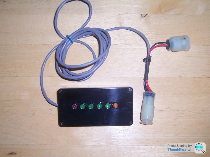
Its not very accurate as the probes are not designed to work outside the narrow band range and the voltage shifts as the probes age, but it will show if you are miles out from where you should be. I did make some display boxes up using LED VU audio level meters that worked quite well if you dont have wide band probes. Otherwise if you can get hold of an analogue test meter with a 0-2 volt range it will work OK.
Less than 1 volt is leaner than 14.7 AFR,
.5 volts is 14.7- you will never see this a static reading as the probe voltage shifts very rapidly for very small mixture change
1 volt is richer than 14.7.
1.2 volts is around 13.5:1
1.4 volts is around 12.5:1,
Its not very accurate as the probes are not designed to work outside the narrow band range and the voltage shifts as the probes age, but it will show if you are miles out from where you should be. I did make some display boxes up using LED VU audio level meters that worked quite well if you dont have wide band probes. Otherwise if you can get hold of an analogue test meter with a 0-2 volt range it will work OK.
I haven't had much time for 14CUX lately, but something occurred to me that I felt I needed to discuss. This stems from past efforts to help Blitz with his anti-shunting quest.
For a long time I have been confused about how the O2 sensor threshold voltage is created. This is called 'o2ReferenceSense' in the rebuild project. It makes perfect sense that this value should be approximately halfway between the high and low outputs of the O2 sensors since it is used in a simple compare operation to determine if the O2 sample is high (rich) or low (lean). This graph https://drive.google.com/open?id=0B5NpvdM0NRFjYklM... shows actual O2 and threshold samples taken at a 1 Hz rate during a road test. The vertical axis is in counts from the analog-to-digital converter (ADC) where 5.00 volts would give a full 8-bit count of 255. The maximum O2 value measured is 60 which is just under 1.2 volts although the average high value seems to be closer to 50 counts or 1.0 volts. The threshold reference is in red and is 23 plus or minus a couple of counts which is about 450 millivolts. I should mention that the O2 samples are from both banks randomly since the same memory location is used for both.
The 450 mv value seems to be created using a resistor divider on one of the two vertical ceramic daughter boards on the ECU main board. The ground reference for this divider comes into the ECU at pin 27 on the 40-pin connector. I suspect that the positive voltage to the divider comes directly from the unregulated battery voltage rather than from the regulated 5 volts (I'll explain below). The output from the divider goes to the channel 13 input of the ADC and results in 450 millivolts as I mentioned.
I never understood why they actually measured this value instead of just hardcoding a fixed value in software but now I have a theory. If the positive voltage to the divider is from a regulated supply, measuring the voltage would be a waste of time since the voltage would always be known and unchanging. However, battery voltage can change significantly (from 12.6 to greater than 15 volts) and so would the output from the divider. This leads me to believe that the O2 high level output also rises with higher battery voltage and this whole voltage divider scheme is just a way of adjusting the threshold to suit a changing O2 output.
By the way, the 'o2ReferenceSense' ADC measurement ($8D) is also done for open-loop maps but the measured value is never used. I believe this was an error or oversight on the part of the developers. Deleting this measuement from the open-loop mux list would shorten the list and slightly improve end-of-list servicing (which includes the serial port).
So, can we use this threshold to affect a noticeable mixture change in closed loop? Many of the O2 measured values are not high or low but somewhere in between. This is because the measurment sample happened while the output was transitioning. To illustrate this, I sorted the O2 samples from low to high and re-graphed them here:
https://drive.google.com/open?id=0B5NpvdM0NRFjNVhm...
Obviously, if the graph was a step function changing the threshold to say 10 or 40 would do nothing. But because the graph is an 'S' curve, changing the threshold would change the grouping ratio and have some sort of effect. The short-term trim should then adjust to get back to 50/50 sampling. The only question is whether the mixture change (toward the rich end, of course) would be enough to help the shunting problem.
Gassing Station | Griffith | Top of Page | What's New | My Stuff