Instructions to change fuel maps on 14CUX Griffith, Chimaera
Discussion


danbourassa said:
It would take very little code at the PROM end of things to make the change you want. I assume you just want to store the 8-bit value in an unused RAM location. If you want, I could help you with this change.
Dan and Robert, you two never cease to amaze me and now you are considering code changes; I never would of believed it. Will you compile your reversed engineered assembly code or edit the executable code in hex? Robert, it’s a really neat idea what you are planning to do and I really hope you get it to work. Humm, when (not if) you crack it I may have to copy you and buy the same gas analyser if you don’t mind.All the best, Steve
robertf03 said:
This evening I worked on a custom ADX to allow data tracing within tunerpro. I'll edit with the link once I zip it all up.
edit: link is http://www.flemcodesign.com/files/14CUX_CHECKSUM2....
the floating oval shows the current cell that is use per Collin and Dan's documentation.
Mark @ Tunerpro sounds pretty enthusiastic about the project and has agreed to host the files. You can now find the definition files on his site. I'm going to play with the cell tracing some this weekend before sending him the updated files and adx file.
Robertedit: link is http://www.flemcodesign.com/files/14CUX_CHECKSUM2....
the floating oval shows the current cell that is use per Collin and Dan's documentation.
Mark @ Tunerpro sounds pretty enthusiastic about the project and has agreed to host the files. You can now find the definition files on his site. I'm going to play with the cell tracing some this weekend before sending him the updated files and adx file.
I’ve finally had a chance to test data tracing on a running engine and you’ll be pleased to hear it worked. I had to create the following so would you like me to add them to the XDF file or would you mind adding them. There is no rush as I’m happy using my version for now.
TRACING MAP 2 FUEL TABLE (new)$4379
TABLE 2 SCALAR (new)$43F9
MAP 2 RPM SAFELY LIMIT (new)$4485
I've also changed TABLE 1 SCALAR to $42E7 (I know it's a work in progress
The only issue I had was the oval highlight was not always positioned exactly over the active cell and sometimes is between cells, also the refresh rate was slow. Is their anything I can change my end.
Thank you in anticipation.
Cheers Steve
Edited by stevesprint on Friday 4th October 23:42
Robert
Thank you for your emails and pointing out TunerPro doesn’t support the exact serial speed of the 14CUX at 7812.5bps. For the benefit of everyone else the data tracing slow refresh rate is caused by errors on the 14CUX serial connection with TunerPro. The connection is error free with the ignition on but once the engine is running the errors start. I wonder if it’s anything to do with the following on Colin’s protocol page at http://alum.wpi.edu/~colinb/14cux_protocol.html , and if so how does RoverGauge overcome the issue.
Thanks again for all your help & good luck with your other project.
Steve
Thank you for your emails and pointing out TunerPro doesn’t support the exact serial speed of the 14CUX at 7812.5bps. For the benefit of everyone else the data tracing slow refresh rate is caused by errors on the 14CUX serial connection with TunerPro. The connection is error free with the ignition on but once the engine is running the errors start. I wonder if it’s anything to do with the following on Colin’s protocol page at http://alum.wpi.edu/~colinb/14cux_protocol.html , and if so how does RoverGauge overcome the issue.
cmb said:
The amount of time required for the 14CUX to send a character over the serial port may change depending on its current state; for example, read requests may be serviced slightly faster before the engine has been started due to the reduced load on the processor.
Robert, I’ve tried 7808bps and 7816bps both with and without your 5ms pause and I’m happy to keep trying. I’ve also noticed in Colin/Dans code dcb.Partity = 0 and dcb.StopBits = 0 does that mean no partity and 1 stopbit?Thanks again for all your help & good luck with your other project.
Steve
danbourassa said:
0x0087 Bit 4: (will force open loop but otherwise unused and should stay zero)
Could RoverGauge read the complete bytes change Bit 4 and send the complete byte back?danbourassa said:
0x0087 Bit 5: Set when RPM > 3400 (this value stored in PROM at 0xC0A7)
I’m thinking if Bit 5 is set when the revs exceed the value stored at 0xC0A7 in the PROM would changing the value at 0xC0A7 to 500 force open loop above 500 revs. Hummm, that’s strange C0A7 in a few PROM I have is 08 9D and that’s 2205 in decimal, I must be having another blonde moment.danbourassa said:
0xC099 This is a byte value in PROM which should normally be zero. Set to non-zero to force open loop.
Would it be possible for RoverGauge to set/unset this address in memory to force open loop on and off.Just a thought
Steve
Today I visited Surry Rolling Road armed with Robert’s TunerPro definition files and Joolz’s Ostrich which all worked faultlessly. I used RoverGauge to see the active cell and the Ostrich to make real time changes. Roberts TunerPro definition files can be downloaded from TunerPro’s website (link below) and I must thank Joolz for all his support and mapping advice.
http://www.tunerpro.net/download/bindefs/Other/14C...
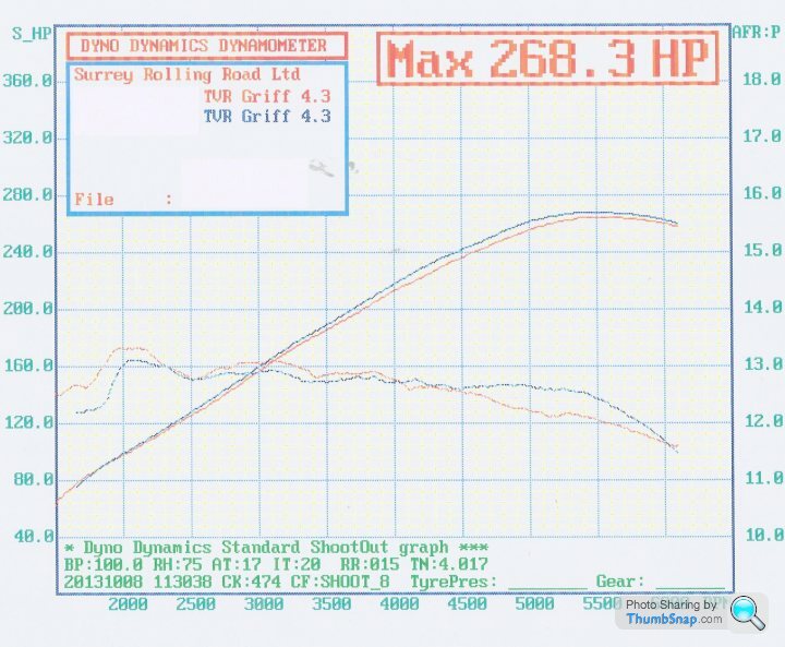
The first run in red proved I’ve successfully copied the complete map data structure from my old precat revision R2422 into TVRs later revision R2967.
I then reduced the bottom entries in the last two columns and had another run. This didn’t change the AFR past 5,500 as the active cell didn’t run along the bottom row so I also changed the 2nd to last row, see blue line. As a result I decided to change the ‘Calc fuel map row’ from 91 to B2, which successfully moved the active cell to bottom row and improved the fuelling past 5,500 rev. However this effectively shifted the entire table up a row and you can see the results in the second graph. I called it a day as I’d proved I can change the AFR and I needed to consider the results and options offline.
Can any 430 Owner with RoverGauge please confirm if the active cell hits your bottom row, you can test safely with data logging turned on.
Dan - Is ‘Calc fuel map row’ a smooth sliding scalar or is it stepped? I ask because I’ve noticed TVR 4.3, TVR4.5 & TVR500 all are 91 and TVR 400’s and Land Rover 3.9’s are B2.
Thanks for everyone’s help, support and encouragement.
Cheers, Steve

http://www.tunerpro.net/download/bindefs/Other/14C...
The first run in red proved I’ve successfully copied the complete map data structure from my old precat revision R2422 into TVRs later revision R2967.
I then reduced the bottom entries in the last two columns and had another run. This didn’t change the AFR past 5,500 as the active cell didn’t run along the bottom row so I also changed the 2nd to last row, see blue line. As a result I decided to change the ‘Calc fuel map row’ from 91 to B2, which successfully moved the active cell to bottom row and improved the fuelling past 5,500 rev. However this effectively shifted the entire table up a row and you can see the results in the second graph. I called it a day as I’d proved I can change the AFR and I needed to consider the results and options offline.
Can any 430 Owner with RoverGauge please confirm if the active cell hits your bottom row, you can test safely with data logging turned on.
Dan - Is ‘Calc fuel map row’ a smooth sliding scalar or is it stepped? I ask because I’ve noticed TVR 4.3, TVR4.5 & TVR500 all are 91 and TVR 400’s and Land Rover 3.9’s are B2.
Thanks for everyone’s help, support and encouragement.
Cheers, Steve
Edited by stevesprint on Monday 21st October 23:08
danbourassa said:
Steve, are you talking about the value at fuel map offset 0x10A that is used from RAM location 0x200A? If so, yes, it's a multiplier and any value is legitimate (my 93 RRC has value 0xB9). Software limits the result of the multiplication so you can't get into trouble by going beyond the table limits. The range of the result is 0x00 (1st row) to 0x70 (last row).
Arrr yes, I see it’s B2 for non cat and B9 for cat, interesting. Thanks for the clear explanation I understand.danbourassa said:
Also, I should mention again that there is a full byte that addresses both the row and column of the fuel map. Usually the fueling point is somewhere between 4 cells on the map. Software does a weighted linear interpolation between the 4 values to calculate a 16-bit fueling value. RoverGauge simplifies this by just highlighting the closest cell to the actual fueling point. So, even though the bottom row was never highlighted, it may have contributed to the fueling calculation. For example, if the row index was 0x67, the second last row would be highlighted, but the last row would be contributing 7/16 to the calculation.
I see and once again thanks for the re-mapping lesson. Credit to Joolz (Spitfire4) as he thought it might be weighted linear interpolation. Does RoverGauge always highlight the top cell of the 4 cells contributing?danbourassa said:
Remember the conversion value? Divide 7,500,000 by 2205. Yes, lowering the RPM cutoff should work.
Dan I certainly do but I thought that was only for RPM limit.danbourassa said:
No, this location (0xC099) is in ROM, so RoverGauge can't change it.
Sorry, yes of cause, therefore would it work if we changed it on the PROM?DanYourTheMan said:
For example, if the row index was 0x67, the second last row would be highlighted, but the last row would be contributing 7/16 to the calculation.
If the last row (7) contributes 7/16 because the lower nibble equals 7 I guess row 6 would contribute the remaining larger proportion of 9/16, which now makes sense.DanYourTheMan said:
No, RoverGauge highlights the closest cell to the fuelling point. If the row index were 0x69 (instead of the 0x67 example earlier) then a last row cell would be highlighted.
I see, I see, that’s really neat how the ECU code moves SMOOTHLY around the fuel table while RoverGauge rounds 67 down to row 6 and rounds 69 up to the bottom row 7. To confirm I understand, when 6A the last row (7) would contribute a larger portion of 10/16 and row 6 would contribute a small portion of 6/16. It’s amazing how much maths an 8-bit processor can handle in a short space of time. I see from Colin’s notes the column index upper nibble runs from 0x0 thru 0xF so I guess the column index lower nibble behaves the same way as the row lower nibble. If so, that must mean column 14 is taken into account until the RPM are 5502 (F0) and above. Once past 5502 rpm (F0) I guess only the last column (15) is taken into account and any further column index rise i.e. from F0 to FF is ignored. Luckily my peek power is at 5500rpm.
Thanks for your patience with me I really appreciate it especially when I’m slowing getting my head around the concepts and then you though more challenges at me. I could do with a good website to read up on the concepts so I wouldn't have to ask so many question.
Thanks again and Cheers from Steve (Grateful) Sprint
Edited by stevesprint on Sunday 13th October 12:28
Robert
Now Dan has taught me the finer thing in life, like ‘weighted linear interpolation’, could this smoothing between the cells be what I’m seeing in TunerPro when the active cell highlight moves between 2 cells and not exactly on a cell? If so it would be really good to overcome the errors on the TunerPro serial link. If you don’t mind I’ll email Mark @ TunerPro to see if he has any suggestions. I hope he doesn’t ask me anything to complicated, as I don’t totally understand the ADX Header Data and the TableMacro.
I hope you have sorted your running problems.
Cheers Steve
danbourassa said:
I just uploaded a few flowcharts to the directory I mentioned above. They are done in PowerPoint but Google allows viewing online. They aren't perfect and I'm sure there will be future revisions, but I think they might be good enough to be useful for our collective effort to understand the 14CUX. Colin reviewed them and he didn't find any obvious blunders. I estimate that the flowcharts only cover about half the code so far. Making them actually helped my understanding but there are still blocks of code that I don't have a clue about. There is also a diagram showing what I think is inside the PAL. I plan to do more when I have time. I hope someone finds them useful.
Dan Thanks for the bins & flow charts, you are certainly making amazing progress, it won't be long until you compile/assemble your own version. Do you really think one day you'll implement Roberts idea to input a wideband Lambda sensor 0-5v signal into the heated screen input? I'm planning to install a wideband lambda sensor over the winter and it would be the ultimate solution.
Thanks for showing us inside the 14cux, Cheers, Steve
blitzracing said:
Target AFR for catalyst engine - 14.35:1 in closed loop- up to 3400 rpm.Above that as per non cat map.
Non cat map. Idle 13.5:1 or a bit richer to get a smooth idle. Acceleration phase- 12.5:1 Full power steady state 13:1. Light cruise 15.4:1
MarkNon cat map. Idle 13.5:1 or a bit richer to get a smooth idle. Acceleration phase- 12.5:1 Full power steady state 13:1. Light cruise 15.4:1
Very very useful info, thanks. Sounds like you have been reading 'How to Power Tune the ROVER V8' by Des Hammill.
Cheers Steve
karlspena said:
Hello everyone. Seems like my truck is running fairly rich at all times. Even though conventional logic tells me it shouldn't since it has an H180 cam installed, so should be breathing more. Do you guys recommend adjusting the map or just fiddling with the adjustment factor?
KarlspenaWelcome to the 14CUX mad house, it’s always good to see a new face.
Before you start making any adjustments you should check in RoverGauge that on full throttle the active cell hits the bottom row or at least the second to last row on the main fuel table. As your truck runs fairly rich all the time you could try reducing the main fuel adjustment factor. When I reduced mine from 6B6C to 6978 the AFR was reduced roughly by .2 to .4, so for example at 2,500rpm it went from 13.1 to 13.4 and at 3,500 from 12.7 to 12.9. In addition I also had to reduce the last two columns on the bottom two rows of the main table to reduce the fuelling further between 4,750 to 5,500rpm.
I hope you don’t have the same issue I’m still experiencing of running to rich at 6,000rpm.
Good Luck, Steve Sprint
Mark
Further to our discussion about the RS-232 output on your AEM AFR gauge I’ve modified a Microsoft sample terminal program to output to file with the time at the beginning of each line. I’m hoping you can run the RoverGauge logger and this time logger at the same time then merge and sort the two log files by time with excel's consolidate function. From there you would be able to see the AFR for each active cell (row and column) in the fuel table. If this actually works I then hope to use a pivot table to automatically load the AFR into an 8 by 16 table like the fuel table.
I don’t know if your AFR gauge outputs, ‘Line Feed’ and or ‘Carriage Return’ so it may not work the first time and create the file called ‘TimeLog.txt’ that should contain the time on each line followed by your AFR. Also, once I know your com port settings and AFR output I can program a command line option to automatically connect.
You can download the time logger from www.stevesprint.com/remap-14cux/TimeLogger.zip but please be gentle as it’s a work in progress to kill or cure a cunning plan.
Please do not hesitate to contact me with any issues.
Good Luck
Steve
Edited by stevesprint on Wednesday 1st January 21:35
Karls
Sounds like you are using an old version of Roberts TunerPro.xdf file. I’ve a newer version that I’ve added the different tune colours to the table titles and added some more scalars. You are welcome to download a copy from
www.stevesprint.com/remap-14cux/TunerPro-xdf.zip . Please do not hesitate to email me with any additions or corrections you require and don’t forget to copy Robert’s 14CUX_CHECKSUM2.0.dll into the TunerPro program directory.
Good news, I’ve now successfully run both loggers simultaneously, RoverGauge logger connected & running plus my AFR Time Stamp Logger with a test file sent via a serial loopback plug. I’ve also worked out how to automatically create an AFR 8x16 table in excel but unfortunately it involves rounding the time so the times match which sadly is not ideal. Once I see the output frequency in a real AFR log file I’ll decide if I need to come up with a better solution. Either way I should be able to create an excel macro to automate the process. (Mark, no pressure as I know you are working on your car and I should really be working on mine). The main thing here is I’ve proved running two loggers in tandem is doable plus I should be able to automatically load the AFR into a table.
Karls, After Googling your PLX M300 it appears your lambda controller can be connected to a PC via the PLX iMFD to PC Link cable plus the interface is documented. Have a look at the following:
http://www.plxdevices.com/product_info.php?id=DATA...
http://www.plxdevices.com/support/software/logger3...
http://www.google.co.uk/url?sa=t&rct=j&q=&...
I'm also not overly concerned about running rich past 5,500rpm as my peak power is at 5,500 but as it nose dives very sharply at 5,500 it would be good to sort it before I start re-mapping the whole of my fuel table in spring next year.
Robert
I hope you have worked out why your Rover is maxing out the fuel trims. Have you ever tried real-time logging via the serial output on your LM-1 with or without LogWorks3?
Mark
Your data logger is very tempting especially at that price but I'm sure you’ll agree my money would be better spent on an AFR gauge like yours with the straight forward RS-232 data stream.
Edited by stevesprint on Wednesday 1st January 21:37
karlspena said:
Mark:
I like the idea of using the existing AD inputs. Is there one unused input? (I have an auto trans, so that one is being used) Can Rovergauge read directly one of these inputs or something else must be changed in the ROM? Let's see what's Dan and Colin's opinion on this.
Dan has considered using the heated screen input for the lambda input but unfortunately the current code on the 14CUX only interprets 12 volts on and off and nothing in between. He has confirmed the Analogue to Digital converter would actually support a varying voltage but he would have to rewrite the program on the 14CUX and modify RoverGauge. I personally can’t believe how complicated the 14CUX code is but Dan has made unbelievable progress so you never know.I like the idea of using the existing AD inputs. Is there one unused input? (I have an auto trans, so that one is being used) Can Rovergauge read directly one of these inputs or something else must be changed in the ROM? Let's see what's Dan and Colin's opinion on this.
karlspena said:
Steve:
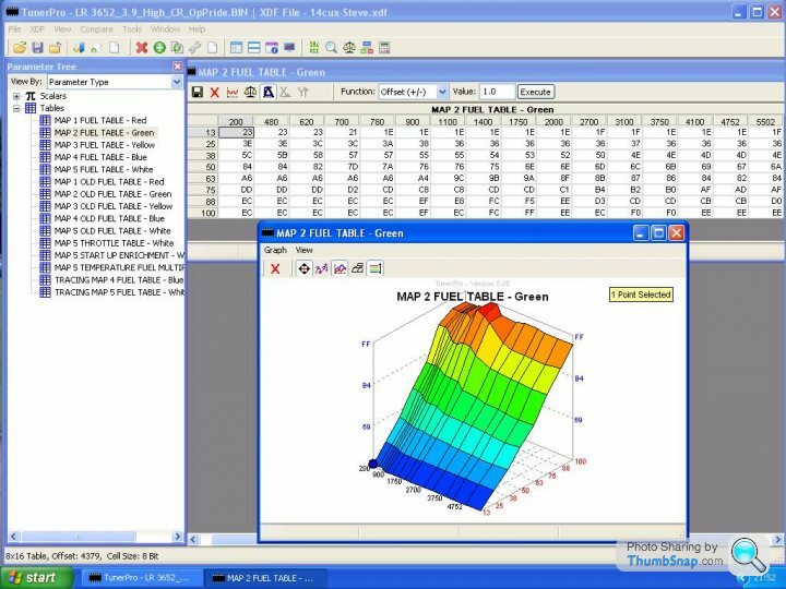
Thanks for the file. It looks great, but this one shows the white map correctly but not the others, you can see it in the screenshots (ie: the green one). I'm gonna try adjusting the position for the maps.
Arrr you mean the graphs. Well that’s very interesting, the green tune graph works correctly for me, with tune 3652, in TunerPro version 5 as you can see below but not in TunerProRT version 5, so it has something to do with the different versions of TunerPro.Thanks for the file. It looks great, but this one shows the white map correctly but not the others, you can see it in the screenshots (ie: the green one). I'm gonna try adjusting the position for the maps.
karlspena said:
My PLX M300 is the older version (black housing) and cannot be connected (at least out of the box) to a PC via the PLX iMFD to PC Link cable. The documentation you found is for the M300-TE which is basically the same iMFD module used with the DM-6 gauge but with an integrated display and some extra logic to adjust for different fuel types. Mine only has analog outputs (both narrow 0-1V and wideband 0-5V). If the onboard AD inputs cannot be used I would be willing to buy the DM-6 AFR combo which has PC output. Maybe someone can help writing a program to adjust the logs for the AFR so it matches Rovergauge's.
I’ll happily have ago at modifying my TimeStampLogger to capture the data stream from the DM-6, but I can’t guarantee I’ll get it working as it looks a lot more complicated than Marks AFR data stream. I would feel awful if you bought one and I struggled to get it working. If not, I would of thought PLX’s Scan XL software would support real-time logging.When you say DM-6 AFR combo do you mean SM-AFR & DM-6? Look’s rather interesting, humm I wonder how much !!!!
Edited by stevesprint on Tuesday 5th November 23:23
karelspna said:
I see, so the autostick and heater screen are no good. What are the other two inputs for?
The A/C input is the only other input that could be spare but I’m sure we’ll have the same issue.karelspna said:
I have TunerPro 5 as well. I'll play a little with the xdf to see if i can find the bug.
As you are running the same version of TunerPro it maybe an issue with different versions of Microsoft .NET framework, I have client version 4 installed. Mind you that doesn't explain why my TunerProRT doesn't display the graph correctly.karelspna said:
Maybe there is a way to synchronize the timestamplogger with rovergauge so the stamps match.
I don’t really want to ask Colin and Dan or expect them to help as they have already gone beyond the call of duty and this is a data issue we can resolve.As both log files will contain the system time there are several ways we can synchronise/merge the files but I would like to see the data frequency before I decide the best method. I could even try adding a merge function to my TimeStampLogger.
I’m very happy to modify my TimeStampLogger to support different AFR sensor modules, to be honest I’m enjoying getting my programming hands dirty again. Plus this whole process will help me decide which AFR Gauge to buy, so in away we are all helping each other.
karlspena said:
One way would be to slope consecutive measurements to obtain an approximate value for the AFR in the timestamps specified on the Rovergauge log. Then just append this value on each row on the rovergauge log file. To avoid big errors the AFR logger can be set to update with as high frequency as possible. I'm already trying to see if I can rig an interface between my analog AFR outputs and the PC using arduino. I'll let you know what happens
My limited programming skills may not stretch to ‘slope consecutive measurements’ but I do know what you mean. As the PLX module outputs 10 times a second I’m sure it will be good enough to append the AFR record with the closest time to each and every entry in the RoverGauge log. While with Mark’s slower Gauge I’ll have to work it the other way around and find the RoverGauge records closest to each of his AFR records.Good luck with the arduino interface.
Does anyone have a sample PLX AFR log file I could use for testing???
Edited by stevesprint on Thursday 7th November 08:24
Jools, Congratulations you've remapped the 14CUX.
I'm very impressed you've put into practise everything our America friends have taught us and successfully re-scaled the larger AFM. I personally thought the standard AFM wasn't restrictive below 250 bhp so I would guess the improved fuelling is also contributing to the increased power and torque, but I'm no expert.
It's also excellent news you have proved mapping a CAT car is simpler than we all first thought and you can actually map the engine up to 3,400rpm from the engines own lambda sensors. Plus it's brilliant the RoverGauge lambda trim shows you the actual percentage correction required and you can enter that percent into TunerPro to make the correct adjustment.
http://www.ebay.co.uk/itm/Electronic-ignition-Mapp...
Interesting, a mappable ignition module for £100, I'll put one on my Santa list.
I'm very impressed you've put into practise everything our America friends have taught us and successfully re-scaled the larger AFM. I personally thought the standard AFM wasn't restrictive below 250 bhp so I would guess the improved fuelling is also contributing to the increased power and torque, but I'm no expert.
It's also excellent news you have proved mapping a CAT car is simpler than we all first thought and you can actually map the engine up to 3,400rpm from the engines own lambda sensors. Plus it's brilliant the RoverGauge lambda trim shows you the actual percentage correction required and you can enter that percent into TunerPro to make the correct adjustment.
Podie said:
Looks like good progress.
What can be done to stop the pinking?
Podie - Sounds like its time Jools start offering his customers a mappable ignition module like this one below for £100. I don't think they would be too complicated to fit, except you do have to lock the mechanical advance.What can be done to stop the pinking?
http://www.ebay.co.uk/itm/Electronic-ignition-Mapp...
Interesting, a mappable ignition module for £100, I'll put one on my Santa list.
Edited by stevesprint on Monday 11th November 09:00
Gassing Station | Griffith | Top of Page | What's New | My Stuff