Citroen door mirror woe's
Discussion


MisterT said:
Hi Brian, great to meet you today at The Royal Oak at Duddington. Really nice surprise to observe you had one of Brian Griffiths mirror kits fitted only to find you were Brian Griffiths. Catch up tomorrow at Burghley
I'll be there for a chat Mr T but I'll need a bacon butty and  first .
Hi all.
I realise that for some of you the words "horse and bolted" may come to mind but I have been asked to put together a "How Too" for those of you who haven't had the pleasure of tackling this job before. I would ask those of you who have fitted this kit to please add to or correct my narrative as you feel necessary.
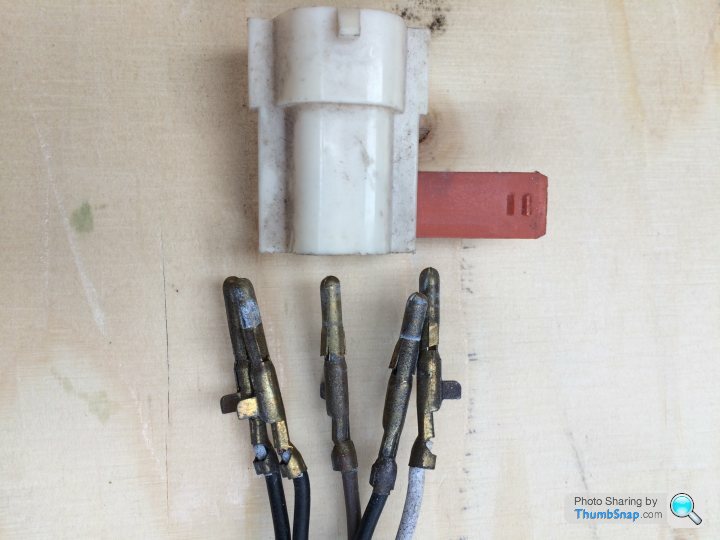
One of the first things to consider before you approach this, is the wiring. If the mirrors are still adjustable by the switch gear then the connector inside the door will need to be disconnected and either dismantled or cut off and rejoined afterwards. You should be able to get to this by removing the door speaker and finding the mirror wiring.
If you want to dismantle the five pin connector, which is how it was installed, this is done by withdrawing the red bar that slides through the side of the body of the connector.
At this point I will issue a WARNING.
Please make a drawing of the position and colour of the wires BEFORE you get carried away and dismantle it without doing so.
I would suggest that some WD40 be applied to the bar to help it on its way bearing in mind this will have been in place for fifteen years, plus.
Push the red bar through as far you can then grip the exposed end with a pair of pliers and pull it out.
The brass pins have a pair of spring out “barbs” that will need to be squashed back into the pin. You can see them in the photo. This will release the pins and allow you to withdraw them.
Since writing this piece I have repaired the loom in my drivers door and have had varying success getting some pins out.
One plug I replaced completely and they wouldn’t move
The next step is to remove the mirror from the door.
Applying some of that WD40 to the base of the mount before you start may help if it's been there for a while but I'm guessing that if you have bought or are thinking of buying one of my kits the mirrors are already suspect!!!
Please take the time to protect the door area around the mirror to prevent any damage to the paintwork. Also, if you can lift the plastic collar and see the grub screw, place a strip of masking tape alongside it and mark its position to give you a starting point when you put the mirror back.
To remove the mirror turn it in an anti-clockwise direction through the two or three indent positions till it stops then take a good grip of it and apply more pressure in the same direction till it releases and continue rotating it carefully till you can lift it free of the door.
There is an outside chance that the inner support post, part number U0649, may break, which apparently, it is designed to do in the event of an accident. Thankfully these parts are available from the usual TVR suppliers.
With the mirror on the bench you will now be able to undo the grub screw with the Allen key from the side of the support post and remove the screwed mount from the post.
At this point with the mirror out, take the time to attend to the wiring if it has been cut and prepare it ready to reconnect. It would also be good to overhaul the inner workings of the mirror by undoing the Torx bolt, removing the washer and rubber buffer. Clean the area and apply some silicone grease or Vaseline to the buffer and replace with the washer and bolt. Final adjustment comes later.
While the mirror is still on the bench you can take the opportunity to replace the old grub-screws with the new stainless steel ones, applying some copper-ease or just plain grease to them to prevent seizing.
Fitting the kit is now quite straight ( Well I think so. :-))
Having first cleaned the area, take the thread clearing tool and insert the plain lead-in end into the brass door insert.
Rotate it in a clockwise direction till it engages with the thread then keep on screwing into the door to clear the thread of any muck and rubbish that's living there.
Unscrew the tool and clear any remaining debris, an old toothbrush is useful.
Before fitting the post take the rubber strips and trial fit them into the door recess. As we know not all our cars are the same so I have cut them too long to allow you can trim them to suit your own car.
Once you have trimmed them to the correct length with a sharp blade you should be able to use some contact adhesive to glue the ends together and make a doughnut that slips over the post.
Time to put the new mounts into the door. Having first placed the large plastic washer, retrieved from the old mount, onto the new mount, screw it into the door by hand till it touches the base, then with the pin tool and an 8mm Allen key tighten the post firmly into the door.
Now take the rubber strips or doughnuts and insert them into the recess around the post.
Turning to the mirrors it's time to adjust the Torx bolt. If you have a bench vice to hand you can put an old mount in the vice to do this, if not, you can do this on the door.
Attach the mirror and tighten the grub screw. Now rotate the mirror body and decide if it is too loose or too tight. Undo the grub screw, remove the mirror and adjust the Torx bolt to attain a smooth but firm movement.
When you are happy with this you can fit the mirrors to the posts in the doors.
I found that the drivers mirror was best in the central of the three positions with the top of the mirror body horizontal, no I didn't use a spirit level, I was then able to adjust the mirror itself to see rearward clearly.
The passenger side needs to be on the inner position to allow the body to be horizontal.
I feel that this makes them look even or level but of course the final lines are up to you.
Reconnecting the wiring may be the last thing to do but you may find that a minor adjustment of the body is needed to get the full use of the mirrors motor travel.
I hope you find this description helpful and that you will be happy with the final result.
Cheers
Brian.G
Edited by Griffo400 on Sunday 7th May 05:58
Edited by Griffo400 on Sunday 7th May 06:02
Edited by Griffo400 on Sunday 7th May 06:06
Edited by Griffo400 on Friday 22 May 09:03
Hmmm, interesting question Horsetan, I haven’t seen a CX in years.
Well I can’t see any reason why it wouldn’t.
I made the pin tool to fit the original screwed mount so that should work.
The thread clearing tool would work but the foam strips would be redundant I think and you may have to paint the new mounts as they may be visible.
An alternative would be to make up with a new shroud using exhaust pipe reducers like Asaad did.
Hope this info is useful and PM me if you would like a set.
Brian.
Edited by Griffo400 on Saturday 14th October 12:31
Hi Phillpot, sorry for the delay in replying.
Yes the weather did put pay to displaying anything outside the car. I just put the parts on the dash in the end.
Another kit I have put together due to repairing my car are these rear wishbone adjusting screws and nuts.
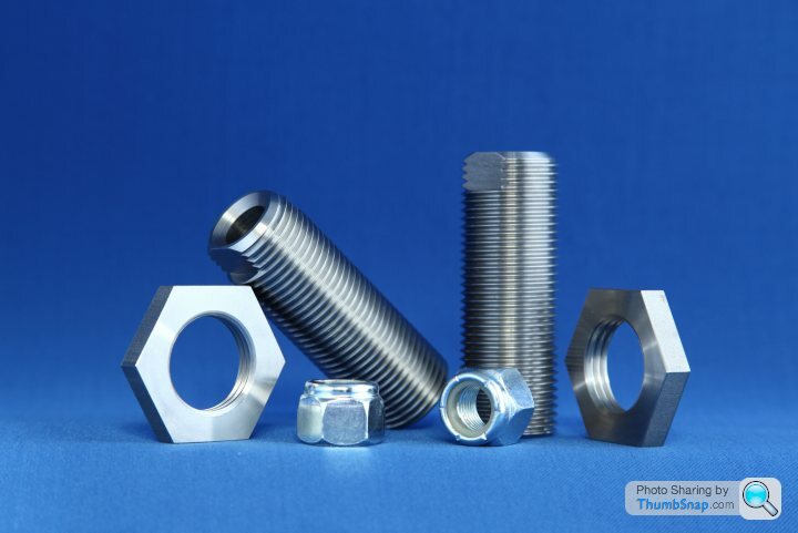
I had to drill mine out as they had rusted solid so I made new ones out of stainless steel. The Nyloc nuts are high tensile steel as per the originals
I’ve also had some new bonnet prop catches made for the Griff, the piece that’s on the inner wing and the threaded ball that screws into the bonnet itself, all stainless.
I was trying to make a new double prop system for the bonnet but I no longer have the facilities to continue with it.
When I have some photos I’ll upload them here.
Cheers.
Brian.
Yes the weather did put pay to displaying anything outside the car. I just put the parts on the dash in the end.
Another kit I have put together due to repairing my car are these rear wishbone adjusting screws and nuts.
I had to drill mine out as they had rusted solid so I made new ones out of stainless steel. The Nyloc nuts are high tensile steel as per the originals
I’ve also had some new bonnet prop catches made for the Griff, the piece that’s on the inner wing and the threaded ball that screws into the bonnet itself, all stainless.
I was trying to make a new double prop system for the bonnet but I no longer have the facilities to continue with it.
When I have some photos I’ll upload them here.
Cheers.
Brian.
RogerDodger said:
Received - fast, courtious, and lovely engineering. Thanks Brian.
A question - how do you make (fabricate) the hex hole in the "tool" ? Punch/push it in? curious from an engineering perspective.
Hi Roger, yes it’s as simple as drilling a hole 0.2 larger than the hex size and punching the hex tool into it. As it’s aluminium the machine could handle it.A question - how do you make (fabricate) the hex hole in the "tool" ? Punch/push it in? curious from an engineering perspective.
Here are the photos of the bonnet parts I’ve been promising folks.
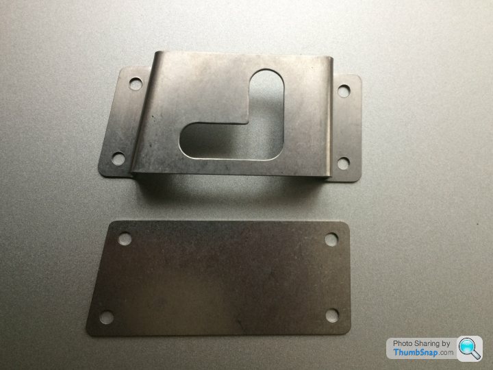
These brackets are as close in size to the original as I could get, the holes will accept 3mm pop rivets. I made the plate to fit under bracket the as I found that the rod had dug into the wing on my Griff.
This is stainless steel so could be polished for the those who like a bit of bling
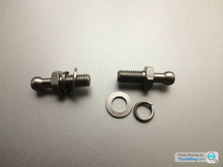
These balls fit into the bonnet and are a copy of the ones on my Griff. Someone needed a set as they had lost them in the rebuild so......I made some more.
I found that the washers were needed to set the correct spacing between the pivots.
If anyone loses these I’ve got some!!
I’m putting a price of £20 for either the bracket or the ball kits to include P&P.
Drop me a line if your interested.
These brackets are as close in size to the original as I could get, the holes will accept 3mm pop rivets. I made the plate to fit under bracket the as I found that the rod had dug into the wing on my Griff.
This is stainless steel so could be polished for the those who like a bit of bling
These balls fit into the bonnet and are a copy of the ones on my Griff. Someone needed a set as they had lost them in the rebuild so......I made some more.
I found that the washers were needed to set the correct spacing between the pivots.
If anyone loses these I’ve got some!!
I’m putting a price of £20 for either the bracket or the ball kits to include P&P.
Drop me a line if your interested.
Hi all. I still have these in stock, so PM me if you’re interested in a set.
The problem I have at the moment ( 21/03/20) is posting the kit to you as the post offices in my area have closed so you may have to wait till things calm down. Sorry.
Brian G
The problem I have at the moment ( 21/03/20) is posting the kit to you as the post offices in my area have closed so you may have to wait till things calm down. Sorry.
Brian G
Edited by Griffo400 on Saturday 21st March 19:14
Edited by Griffo400 on Saturday 21st March 19:16


Gassing Station | Griffith | Top of Page | What's New | My Stuff