1995 Griffith 500 restoration
Discussion


Polly Grigora said:
Enjoyed reading the above, an eye opener to say the least
You have to understand, to produce cheap reliable cars the tolerances are finer than low volume hand built vehicles because every part produced must fit straight off the tools. There isn’t time to faff or adjust. It has to fit perfectly straight away then it’s off to the next process. If a part needs fettling before fitting its simply scrap so the process to make and check it had to be improved.Then you have service intervals. A part could prematurely wear out from designated design. Cost then enters the process. How much to improve the part or change the service interval so less time is given for its useable life. That obviously is to do with moving components and not the body.
Just the tip of the iceberg of what’s involved in high volume production vehicles.
Ford looked at Jaguars production capabilities and could see it could be vastly improved which it did. Jaguars highest volume vehicle to date was the X type and it wasn’t a Mondeo it was its own body design. The floor pan wasn’t mondeo as the design was different, the tooling was different as I remember it being built. The S type floorpan was used from a Lincoln but modified to suit a Jaguar. When the supercharged version was developed the rear diff wasn’t strong enough to cope with the max power and torque of the engine. So the cost effective way to engineer the issue was put a lower Rev limiter on the engine. So no standard s type r engine actually produces the 400bhp it’s capable of. It was deemed performance was good enough with a lower rev limit. I still find it all interesting.
Lastly, Ford Bridgend engine plant would do hot engine tests on production samples, all manufacturers do this. So the dyno’s would be fitted up with said engines and put through there paces. There would be a 24hr flat out run followed by a complete strip down measuring components for wear. A single Jag v8 supercharged engine would use a tanker of fuel in 24hrs. I always thought that wow until my latest work colleague told me how many tons of fuel an aircraft jet engine went through on similar tests.
I enjoy engineering can you tell

Murph7355 said:
RobXjcoupe said:
....Just wanted to see how it looked with the subtle mod. I’m liking it. ...
Possibly being a bit dense...but is the "subtle mod" the dials being slightly more recessed than standard?One of a few things that I think could be better on the Griffith are those bezels...they look like cheap plastic to my eyes. Recessing them (assuming they are!) does help. But what I think they really need is to be half the width.
Very much admiring your skills on this stuff.
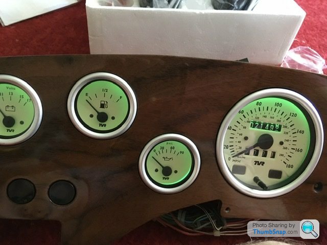
Chatting with Mr Wiggins (who made the new dash) I went through a few different ideas. I believe it’s the first Griff 500 dash he has made with recessed dials. As you say not the best looking bezels but they are all crimped on and rather expensive to replace hence I went with a recessed look so the dials are sitting in the veneer and not on it. The switch panel has also been replaced with a new veneer panel but I haven’t got round to that yet. Little issues I would have changed if I’d looked at it in more detail but it’s done now.
I’ve also ordered a set of green led backlighting bulbs for all the dials. This will then match the alpine headunit illumination and the new heated seat button illumination. Just ties everything together in that respect
Matthew Poxon said:
Fantastic thread Rob, really enjoyed reading this. Love the enhanced seats and the little details such as the heated seat buttons in the door cards.
Thank you, I try my best. Hopefully it gives a few ideas to another Griff owner that decides to take the plunge and start another restoration. Edited by RobXjcoupe on Monday 11th September 20:45
Murph7355 said:
RobXjcoupe said:
Yep the dials are recessed, on the original dash this would be impossible as it’s a bit of steel sheet and veneer glued on.
Chatting with Mr Wiggins (who made the new dash) I went through a few different ideas. I believe it’s the first Griff 500 dash he has made with recessed dials. As you say not the best looking bezels but they are all crimped on and rather expensive to replace hence I went with a recessed look so the dials are sitting in the veneer and not on it. The switch panel has also been replaced with a new veneer panel but I haven’t got round to that yet. Little issues I would have changed if I’d looked at it in more detail but it’s done now.
I’ve also ordered a set of green led backlighting bulbs for all the dials. This will then match the alpine headunit illumination and the new heated seat button illumination. Just ties everything together in that respect

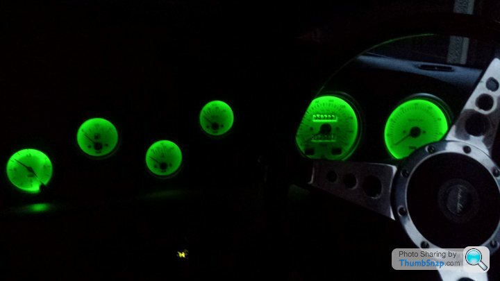
I actually quite like the cream illumination. Doesn't especially help be able to see anything, but looks quite cool
You can customise the colour of my HU's lighting too.Be careful on LED brightness too. I had metal, LED backlit switches put on mine when I had it recommissioned, and think you can see them from outer space

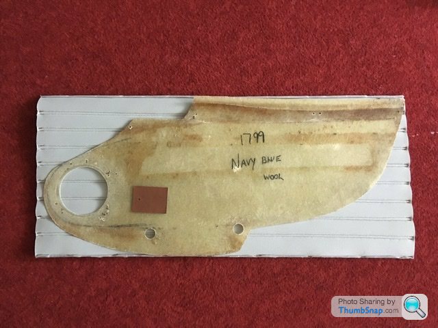
Back to the Trevor. The panel within the door trim that holds the audio speaker. I’ve already trimmed one, the other hand later today. The original speaker hole was a little too big for my replacement speaker. Being fibreglass it makes things so much easier to repair and then cut a new smaller hole.

I should have showed both left and right hand panels together to demonstrate how different in shape they are which doesn’t help much when trimming with specific style lines that need to match as a handed pair.
The black marker line is the factory original and shows where this panel sits within the outer trim. That’s the only guide I have to line up the new speaker hole.
But before marking new speaker holes I need to fill in the existing hole. This was backfilled with new fibreglass so as I could lay my new speaker hole template on the panel. I cleaned and prepped the edges with a bit of 120 grit emery cloth then used brown packing tape on the back of the panel to stop the liquid resin flowing away then carefully used glassfibre matting to back fill the hole. 3 layers. Once cured, tape is removed, file the rough edges and it’s as simple as that.
Picture below shows the panel on the other side. It’s a clearer picture of the difference in hole diameters I need. Also the amount of random screw holes to fit the previous front speakers. I filled all those but it’s like someone was possessed with a small drill in the past.
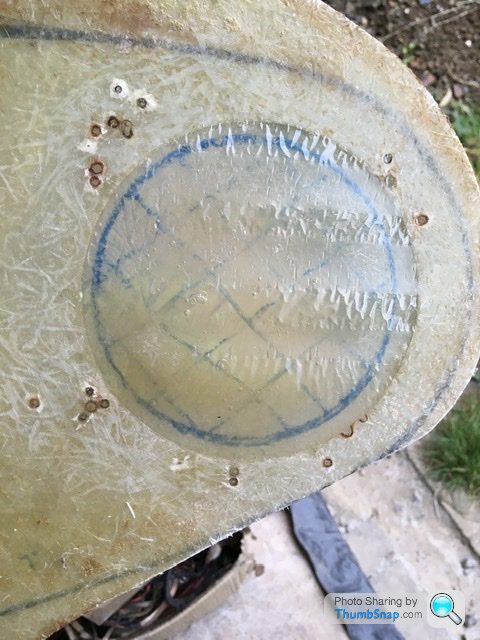
Looking at the above picture it also shows how little extra material I need but it’s the only way to repair and cut again keeping the original panel thickness. My blue circle isn’t central to the original hole. This is due to the speaker surround being wider than the original so needs a little extra space one side. When trimmed and fitted it’s details like this that vanish.
I should have showed both left and right hand panels together to demonstrate how different in shape they are which doesn’t help much when trimming with specific style lines that need to match as a handed pair.
The black marker line is the factory original and shows where this panel sits within the outer trim. That’s the only guide I have to line up the new speaker hole.
But before marking new speaker holes I need to fill in the existing hole. This was backfilled with new fibreglass so as I could lay my new speaker hole template on the panel. I cleaned and prepped the edges with a bit of 120 grit emery cloth then used brown packing tape on the back of the panel to stop the liquid resin flowing away then carefully used glassfibre matting to back fill the hole. 3 layers. Once cured, tape is removed, file the rough edges and it’s as simple as that.
Picture below shows the panel on the other side. It’s a clearer picture of the difference in hole diameters I need. Also the amount of random screw holes to fit the previous front speakers. I filled all those but it’s like someone was possessed with a small drill in the past.
Looking at the above picture it also shows how little extra material I need but it’s the only way to repair and cut again keeping the original panel thickness. My blue circle isn’t central to the original hole. This is due to the speaker surround being wider than the original so needs a little extra space one side. When trimmed and fitted it’s details like this that vanish.

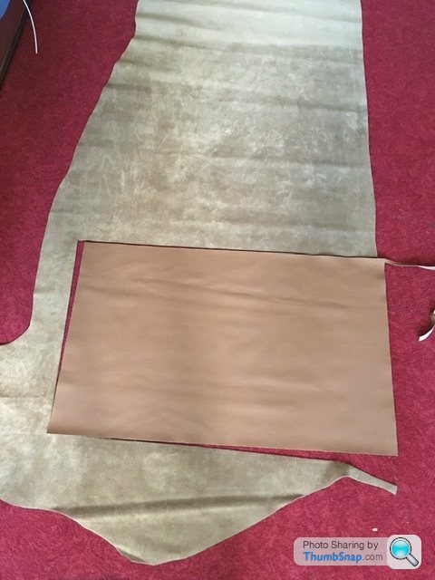
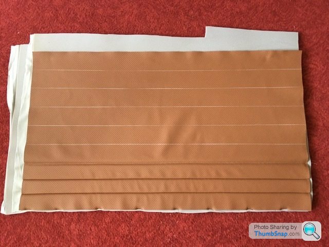
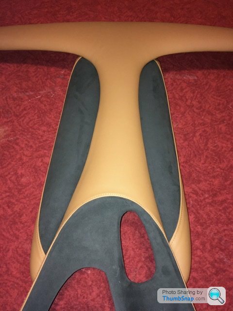
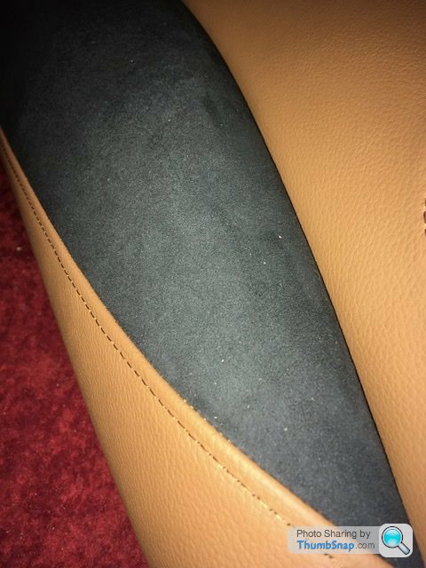
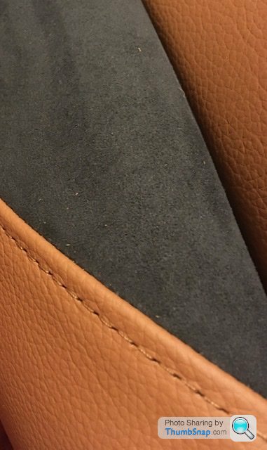
Above is the leather cut from half a hide to cover the door panel with the tuck and roll pleats.
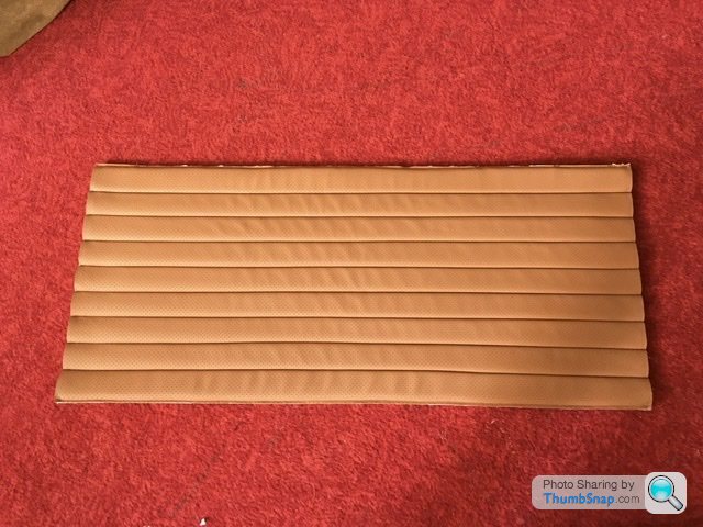
There are 9 pleats to stitch which means I need to add double seam allowance between each pleat plus depending on the scrim foam used you lose a little again which reduces the finished width. On this particular panel I’ve added an extra 160mm so the finished panel covers the area required. Last of the pictures shows the back of the stitched panel with the fibreglass trim on top showing it still needs a little stretching to fit. That bit is important as it’s how you get the leather or vinyl nice and taught to give a smooth finish.
lancepar said:
Rob,
Another thread too late regarding instument illumination, might be useful to others.
https://www.pistonheads.com/gassing/topic.asp?h=0&...
Lance

Had a little read. I think the cream and white face dials work well with the coloured backlit led bulbs. Black faced perhaps not as the black will absorb coloured light.Another thread too late regarding instument illumination, might be useful to others.
https://www.pistonheads.com/gassing/topic.asp?h=0&...
Lance

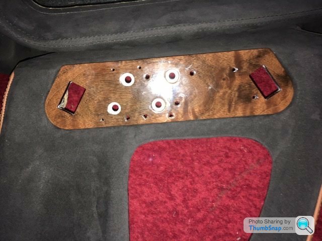
Been plodding on with this. Main centre console now trimmed. That new wood panel didn’t fit the recess. New fibreglass was added behind the offending areas so as I could grind away without leaving any holes. Then first attempt at a cover was too tight a fit and split one side when pulling to remove a bit of a wrinkle. Not impressed as this is glued on and meant start again. 2nd version as pictured with the dash roughly placed on top. I’ve got the bolster left and gearstick gaiter to trim which then completes all the standard tvr parts.
Matthew Poxon said:
I cannot wait to see what the interior looks like finished, I really look of the parts I have seen so far, they look awesome ??
Not a massive fan of the green backlighting on the dials, but then I am a traditionalist and like the old skool cream dials and these things are subjective.
I can’t wait to see what is next, please keep posting pics ??
Patience Not a massive fan of the green backlighting on the dials, but then I am a traditionalist and like the old skool cream dials and these things are subjective.
I can’t wait to see what is next, please keep posting pics ??
The green backlight in the dials is because I have a green illuminated alpine headunit and those heated seat buttons have a green illumination.
I need to order carpet next. Phantom grey I think the colour is called. The transmission tunnel needs carpet before the centre console is fitted. Probably some other bits…..always something that’s missed but that restorations for you. Oh just remembered a couple of speaker enclosures to build also…… See always something else.
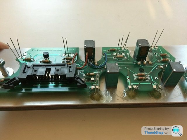
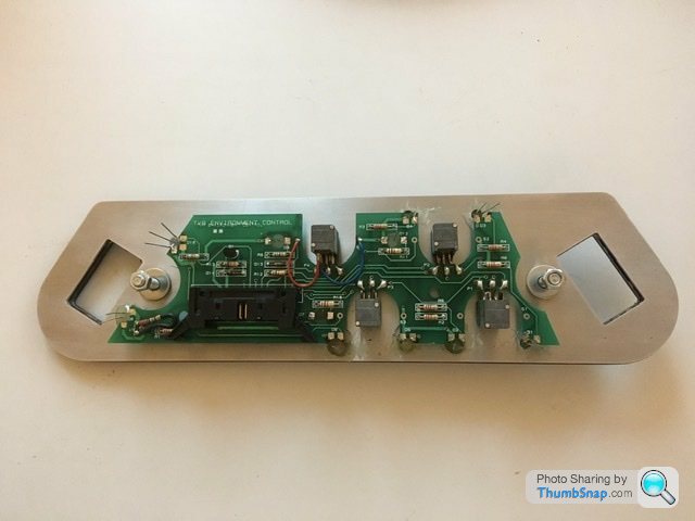
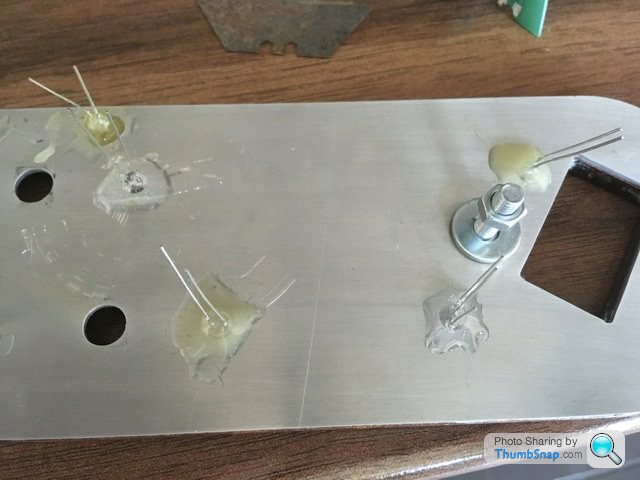
Had a bit of quiet time over the weekend fiddling with the circuit board that fits behind the heater control word veneered panel. As the new panel is substantially thicker to allow the veneer to be attached to a ply base first there were a few adjustments to the back of the new panel to get the indicator leds flush with the front. These then had a blob of araldite to secure in place at the back as per TVR
The old panel below. Clearly seen better days
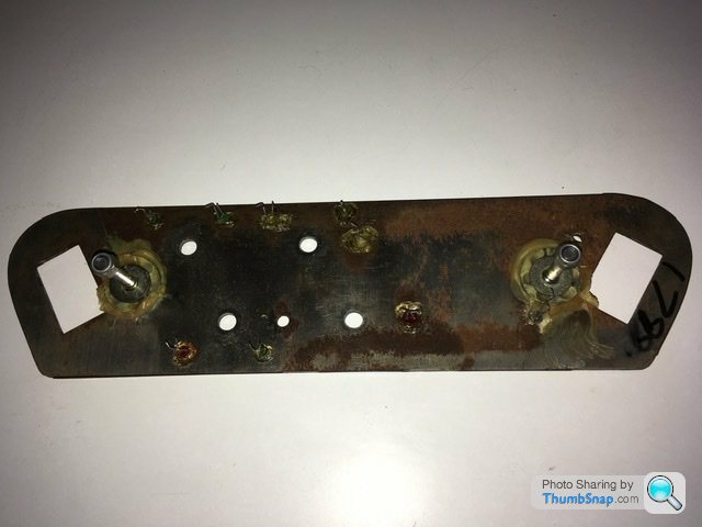
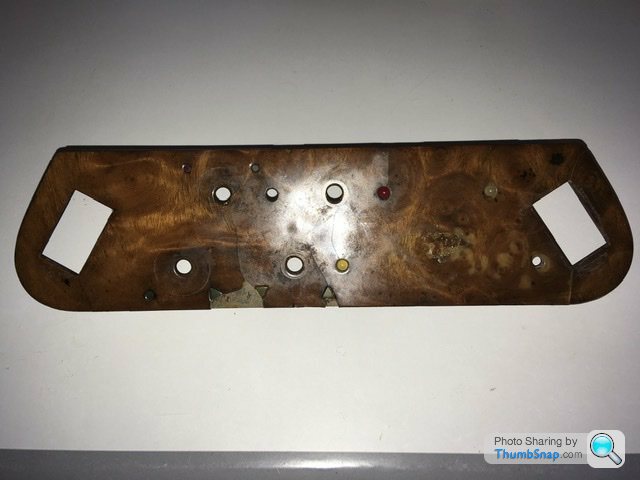
The old panel below. Clearly seen better days
Not sure about the wow……..a compliment is a compliment though
Well I thought I would check the new leds before finalising the soldering? low and behold I have a dud!
Not that well thought out though as I had glued it into position first.
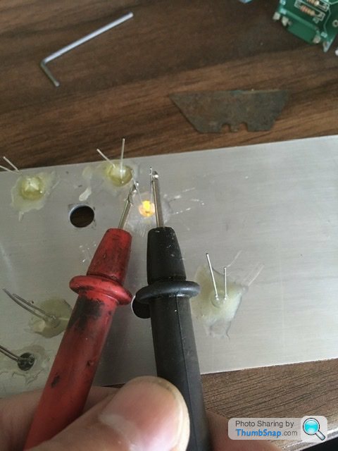
For future reference when looking at the circuit board as fitted to the veneered panel, the positive leg of the led is to the right on all positions on the circuit board
Well I thought I would check the new leds before finalising the soldering? low and behold I have a dud!
Not that well thought out though as I had glued it into position first.
For future reference when looking at the circuit board as fitted to the veneered panel, the positive leg of the led is to the right on all positions on the circuit board
Replacement led arrived this morning so cracked on to finish the heater controls.
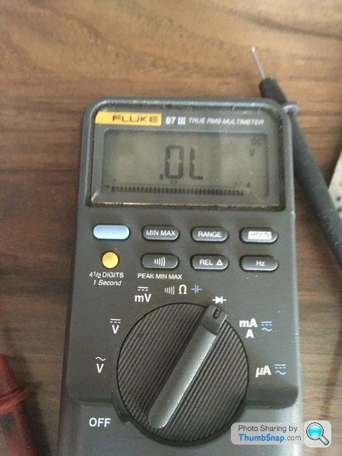
Multimeter to diode and I checked and triple checked all was good to glue in the replacement diode and solder all the new components to the circuit board.
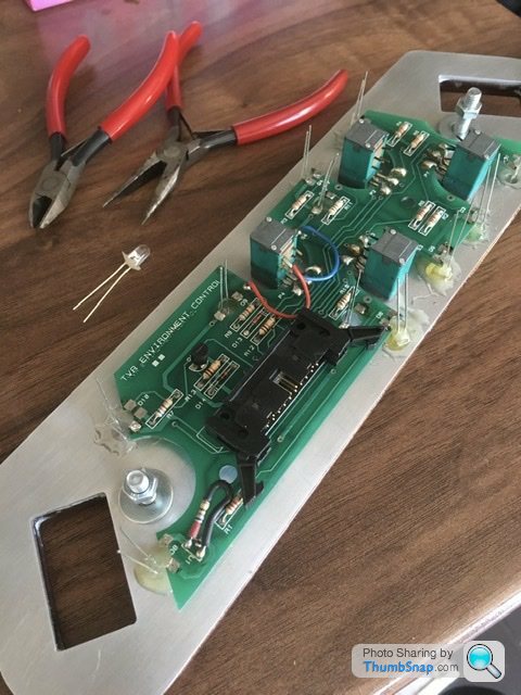
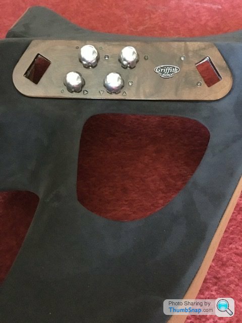
Oh and to note I had to reduce the diameter of a socket so as it would fit into the veneer pocket to tighten up the 4 securing nuts on the 4 rotary switches.
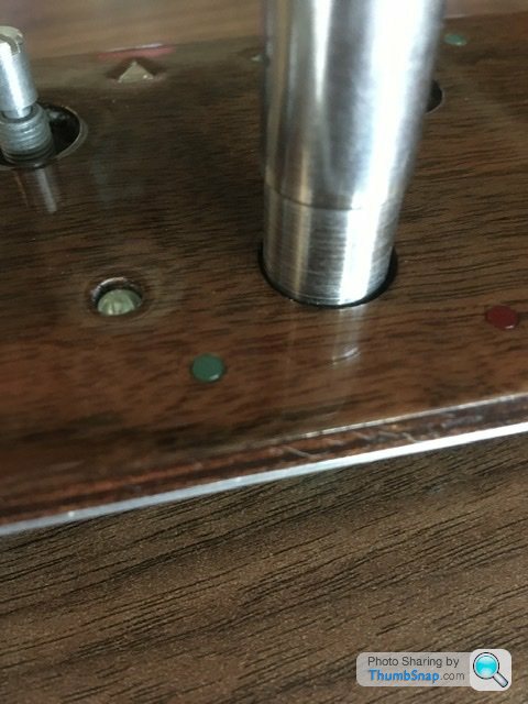
I machined that a while back.
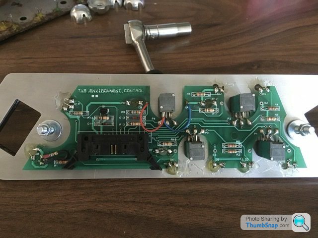
Above shows components all soldered into position. I then checked the diodes again, which all work so anything not lighting up when plugging the unit back in will be a circuit issue.
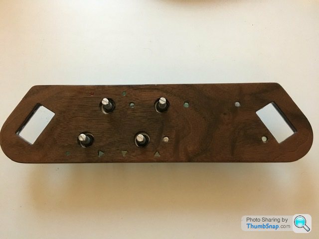
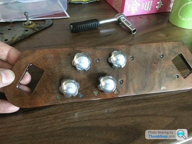
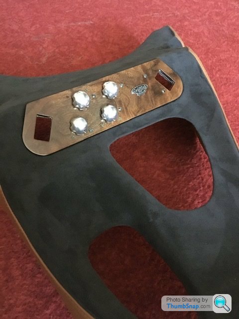
Lastly picture below with the control knobs fitted. I gave them a polish before hand to look as good as new again.
Multimeter to diode and I checked and triple checked all was good to glue in the replacement diode and solder all the new components to the circuit board.
Oh and to note I had to reduce the diameter of a socket so as it would fit into the veneer pocket to tighten up the 4 securing nuts on the 4 rotary switches.
I machined that a while back.
Above shows components all soldered into position. I then checked the diodes again, which all work so anything not lighting up when plugging the unit back in will be a circuit issue.
Lastly picture below with the control knobs fitted. I gave them a polish before hand to look as good as new again.
Thank you for the positive comments. I do try to explain in straight forward detail. Lathe work or any machining is my trade or I should say was my trade of 31 years. All manual toolroom stuff. Was also involved with automotive body tooling, pre production and production stuff.
Now I help teach basic engineering to college students. Pay is shocking but I do have a full engineering workshop at my disposal. Not quite a Ford motor company toolroom but enough for my needs
Now I help teach basic engineering to college students. Pay is shocking but I do have a full engineering workshop at my disposal. Not quite a Ford motor company toolroom but enough for my needs
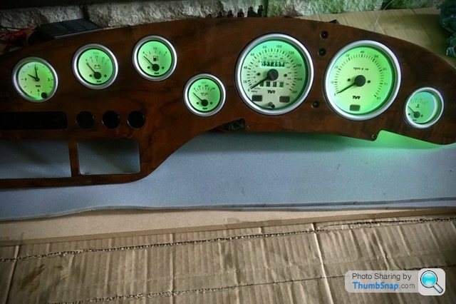
Just finalising the dash refitting the wiring etc.
I put a constant 12v through the illumination bulbs as I had been testing adhoc as I built up the dials. My repaired temp gauge body is a little greener but all look good to be honest.
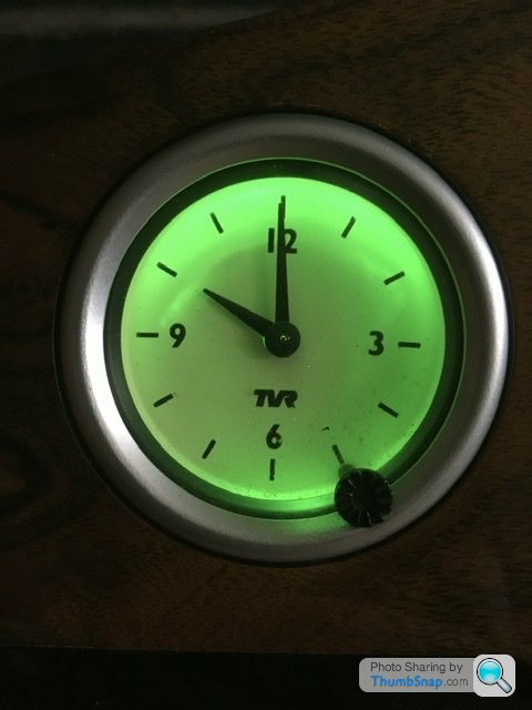
A more detailed look I noticed the time clock has a bit of shadow and dirt behind the glass.
The bezels are crimped around the tvr dials which makes it extremely difficult to remove to simple wipe a bit of dirt away. Undecided whether to dismantle that or not. I’ve ordered another bulb for it which has side illumination so fingers crossed it gets rid of the shadow and possibly doesn’t highlight the dirt inside.
Gassing Station | Griffith | Top of Page | What's New | My Stuff