1995 Griffith 500 restoration
Discussion


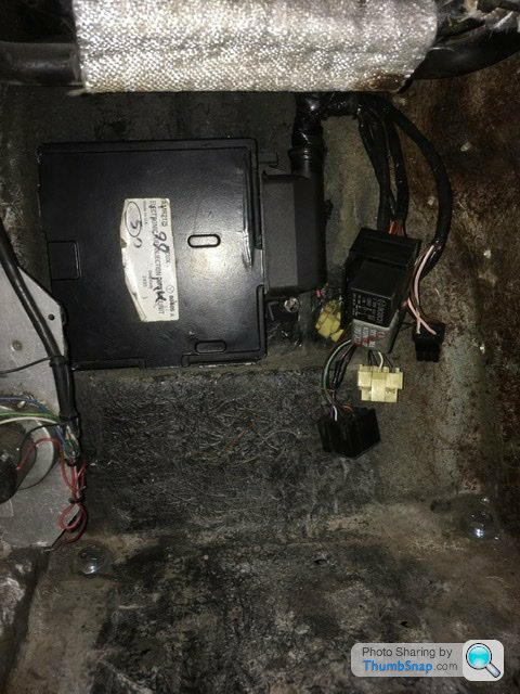
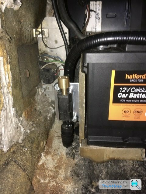
Ecu now fitted where fuse box was. Looking at the space and cable length I would think TVR made that recess specifically for it. Obviously changed there minds at some point.
The strip of relays will now be attached to the back of the battery box in front of the ecu. To bolt them above would make them inaccessible as the heater pipes are at the same height and once the dash is fitted it would be a bit of a mare getting in the footwell and bending arms upwards if you get my drift.
Just above the back of the battery is a better position to see and remove as and when needed.
Also I removed the cable ties holding other wiring to the heater pipes. So that’s all looking a bit more professional. Possibly need to unwrap and wrap again in a new position but not quite yet. I noticed the heater pipes have no support brackets. Held in place via the rubber hose connections which again isn’t ideal. Another job to do!
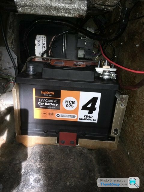
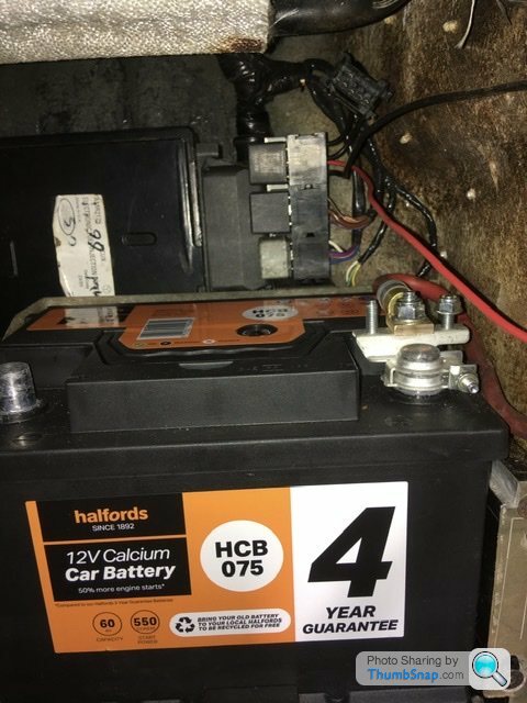
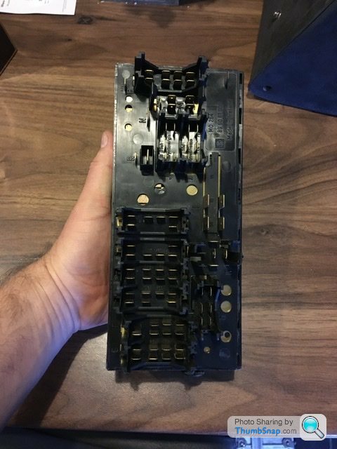
Not pretty pictures but it shows the now secured relays, ecu and battery in position. The battery box is still secured from under the car but I can now remove the battery without having to get underneath and break the waterproof seals to the securing bolts. The red painted clamp on the front base of the battery box firmly secures the battery against a similar clamp on the other side of the battery. Remove the clamp and the battery will simply slide forwards.
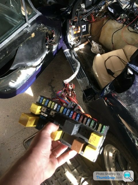
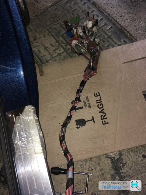
Now I need to shorten the wiring to the fuse box that will be mounted in the glovebox to complete the better access to fuses and remaining relays. Picture below shows the true length of the wiring loom which if kept original is cable tied to all manner of things to try to shorten it. A few hours work there but it will keep the top of the battery free from any coiled up wiring. Once done I can finish off the mods to the electric window wiring circuits and tidy up the cables going into the doors with the new speaker cables all wrapped in new conduit. It’s the details that make the difference but they do take time.
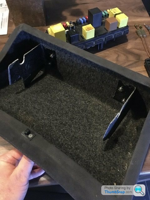
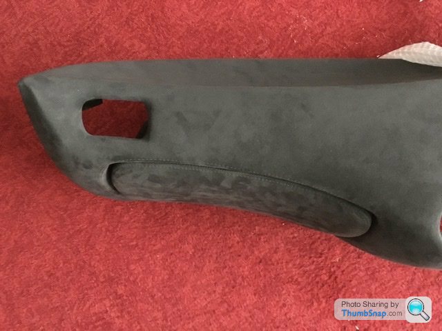
Above shows the fuse box mounts within the glovebox. Basically I’ve cut up the original tvr glassfibre mount that’s used in the footwell.
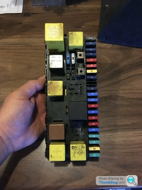
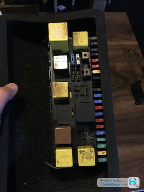
Below is the fuse box, new fuses fitted mostly (as I ran out of certain sizes so will order a few more) and to the correct rating as per the tvr handbook. Interestingly my handbook shows the heated seat fuse and relay position now supplies a radiator fan. So I have separate fuses and relays for each of the 2 radiator cooling fans. I don’t have a dedicated spare for the heated seat elements I’ll be fitting. Bit of a pain as I found the cables underneath the centre console that would have supplied the seats.
The back of the fuse box uses 67 connections. I’ve ordered new ones ready to shorten that part of the wiring loom. I’ll be cutting approx 600mm off the length so a fair bit.
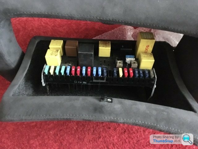
Last picture below of the fuse box inside the glovebox. It needs pushing forward about 15mm for perfect access to remove any fuse in the future. Once I’ve fixed that issue I’ll put a hole in the back of the glovebox to feed the wiring through.
Previously I’ve nearly fitted the fuse box in the glovebox. I then offered it up within the dash and found the glovebox didn’t open enough to allow easy access to the row of fuses……hmmm I thought!
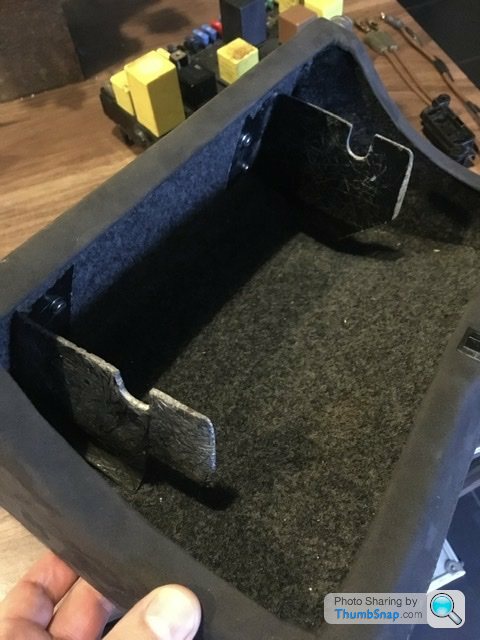
So tried again with the fuses the other way round which makes more sense as it’s the same way round as the original position.
A bit more cutting and filing of the brackets and I’m happy with its position now.

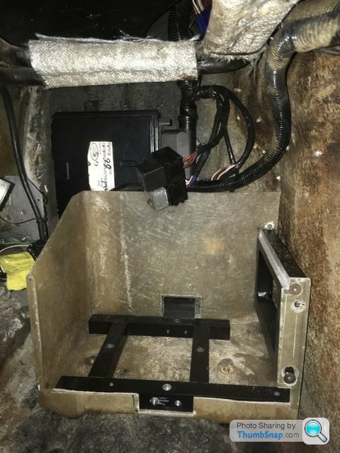
The picture above just shows the space for the relays from a slightly lower position. To be honest I’ve never had the need to remove any of those ever. The ones that seem to play up are the ecu and fuel pump relays, which I assume is because they used to float around on top of the battery. Hopefully mounting the wiring securely will help the car to be more reliable. If not at least I can now get to the fuses and relays a little easier as and when any future issues arise.
I can now cut a suitable hole in the back of the glovebox for wiring access
So tried again with the fuses the other way round which makes more sense as it’s the same way round as the original position.
A bit more cutting and filing of the brackets and I’m happy with its position now.
The picture above just shows the space for the relays from a slightly lower position. To be honest I’ve never had the need to remove any of those ever. The ones that seem to play up are the ecu and fuel pump relays, which I assume is because they used to float around on top of the battery. Hopefully mounting the wiring securely will help the car to be more reliable. If not at least I can now get to the fuses and relays a little easier as and when any future issues arise.
I can now cut a suitable hole in the back of the glovebox for wiring access

RobXjcoupe said:
Polly Grigora said:
Thank you, didn’t even think about that. Perfect space for the heated seat circuit fuse 
So technically that circuit would be live without the ignition switched on but requires the window switch to be live to activate the relay to switch power to make the windows go up. I’m saying this out loud in case this is read in the future sometime.
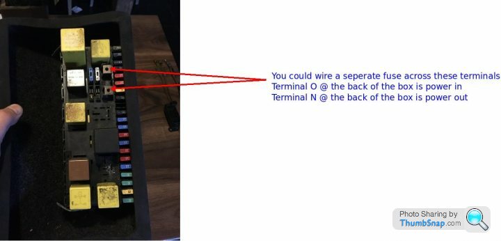
Ideally we want zero live until the ignition is switched on. So I really want to find the main switched output and connect O to that.
If anyone could point me in that direction please. Saves myself a bit of time
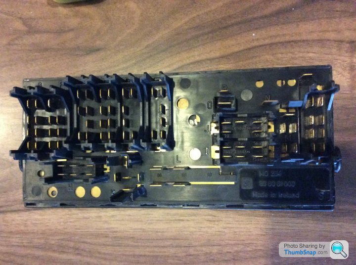
So with a little help and a bit of testing myself I’ve found various switched lives. The one I’m going to use is connection R directly above connection O.
The spade connection makes it easier to loop and is the shortest possible route being as it’s live.
Now I can create the 3 switched main lives. Above I can fit a 30amp midi fuse and come off connection N for the window circuit. The hot start and heated seats will come off the top before the midi fuse and straight into 2 separate inline fuse holders. That way I still have perfect access to all fuses within the glove box.
So once the new terminals arrive I can now shorten the loom and add the extra circuits and wrap as one. Job for the weekend
Polly Grigora said:
RobXjcoupe said:
Ideally we want zero live until the ignition is switched on. So I really want to find the main switched output and connect O to that.
If anyone could point me in that direction please. Saves myself a bit of time
If I'm reading this correctly.....If anyone could point me in that direction please. Saves myself a bit of time
You want a switched unfused ignition supply for the terminal 30 contacts of the relays?
If the above is the case you would be over-loading the ignition switch and defeating the purpose of the relays. A main ignition relay would be needed to supply the relays you're adding
There's nothing wrong with permanent supplies to the terminal 30 contacts of relays and the supplies to the relays can be fused
If I'm reading this incorrectly.....Ignore me
So my thoughts were to only make the additional relays live once the ignition is turned on. So all terminals zero volts until the ignition is turned on.
I thought the main ignition relay would be the place to start. So that relay is supplied via an 80 amp fuse from the battery which is the main power supply from the battery.
Then once that relay is energised it supplies everything so to speak save 2 or 3 fused low current circuits.
I’m thinking once that relay is energised there must be another connection unfused I can tap into and then with appropriate sized fuses supply 3 additional circuits. My thinking is zero current drain in case those relays fail as once the ignition is turned off I just have alarm power, clock/radio memory and ecu memory feeding off the battery. Does that make sense.
I understand I can have a fused permanent live to the relays as technically they haven’t been energised so I’m thinking more a double pole switch. But in the case of the relay the permanent high current input and the low current switched input are both zero volts with the ignition off.
Does that make sense?
Polly Grigora said:
Meant to post this earlier
You're really going to town on the electrics and the job looks top class, am impressed with your decision to remove much cable by shortening the fusebox harness and terminating all cables with new terminals
TVR must have been planning to fit the fusebox on the roof
Thank you for taking the time to check things through. Putting the mirrors control circuit to the windscreen wipers is a good idea but I’m still short of two circuits. I read your posts this morning and have been thinking about it all day the pro’s and con’s so to speak. I think with the age of the components I’m using it would be best not to do as I first thought. I can create a bus bar across the midi fuse holder and take 3 circuits off that via a simple loop underneath from the main battery input. Job done. No extra strain on any other wiring what so ever then. I think that’s the sensible thing to do. So that’s now the plan with the extra wiring circuits You're really going to town on the electrics and the job looks top class, am impressed with your decision to remove much cable by shortening the fusebox harness and terminating all cables with new terminals
TVR must have been planning to fit the fusebox on the roof
Whilst thinking about wiring I had a whole workshop to use to make a couple of other bits to repair parts.
So further back in the thread I showed the issue I found after the new paint regarding the brass nut held within the glassfibre having been ripped out and not put back prior to a new coat of paint.
TVR fitted a crudely cut bit of rubber to hide that nut under the part that grubscrews the mirrors in place. So as glassfibre is messy… for me anyway, to refit that brass nut I’ve made a 3mm think nylon washer that will cover the repair and make it look neat. The idea is to seal that in place also to stop water getting under it. I’ve actually bought another owners machined parts to screw on top being the slightly extended versions of the part you grubscrew the mirrors to. Easier to fit the door mirrors if I ever get them back?! Pictures below saves myself the extra words
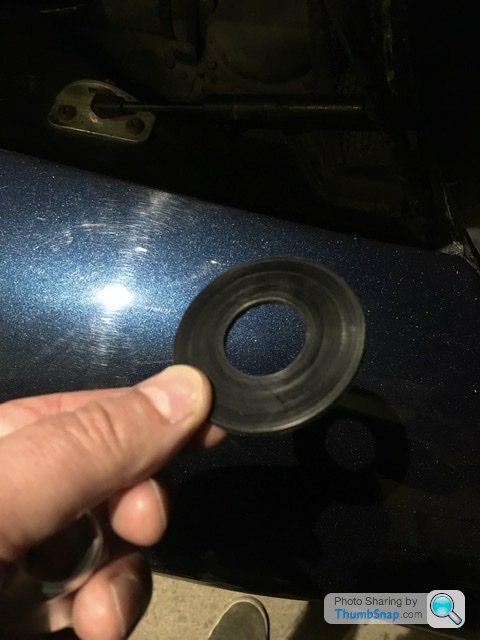
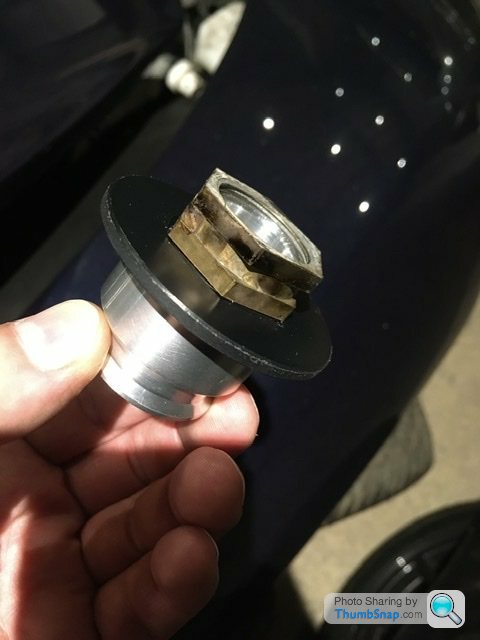

Simple and does the job I think. The passenger door doesn’t need any repairs but again with that black nylon washer in place it looks neat and factory fitted.
So further back in the thread I showed the issue I found after the new paint regarding the brass nut held within the glassfibre having been ripped out and not put back prior to a new coat of paint.
TVR fitted a crudely cut bit of rubber to hide that nut under the part that grubscrews the mirrors in place. So as glassfibre is messy… for me anyway, to refit that brass nut I’ve made a 3mm think nylon washer that will cover the repair and make it look neat. The idea is to seal that in place also to stop water getting under it. I’ve actually bought another owners machined parts to screw on top being the slightly extended versions of the part you grubscrew the mirrors to. Easier to fit the door mirrors if I ever get them back?! Pictures below saves myself the extra words
Simple and does the job I think. The passenger door doesn’t need any repairs but again with that black nylon washer in place it looks neat and factory fitted.
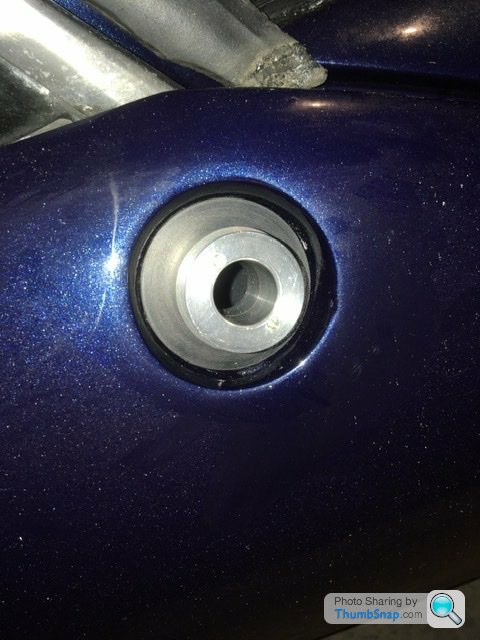
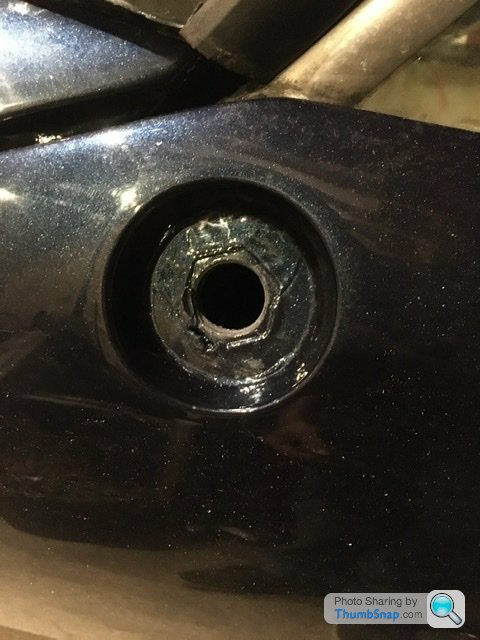
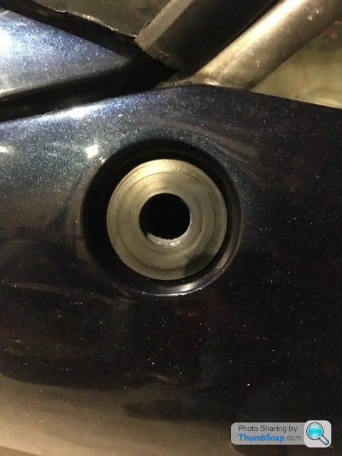
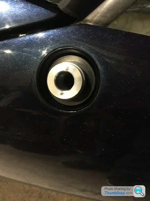
The other part I made this morning was another housing for the temperature gauge. The first one flew from the lathe as I tried to machine the back for the bulb holder. Wasn’t impressed as it was nearly finished. So started again and decided to mill the back instead to create a square shaped bulb holder rather than a round version via a 4 jaw Chuck in a lathe.

I haven’t fitted the bezel yet in case I need to do any adjustments to the sizes to fit in the new veneered dashboard. It’s a Pete Wiggins dash but I’ve asked for the gauges to have a recessed fit rather than stuck on top fit. Just to give that slight difference to match the buttons on the dash that are flush with the veneer.
I haven’t fitted the bezel yet in case I need to do any adjustments to the sizes to fit in the new veneered dashboard. It’s a Pete Wiggins dash but I’ve asked for the gauges to have a recessed fit rather than stuck on top fit. Just to give that slight difference to match the buttons on the dash that are flush with the veneer.
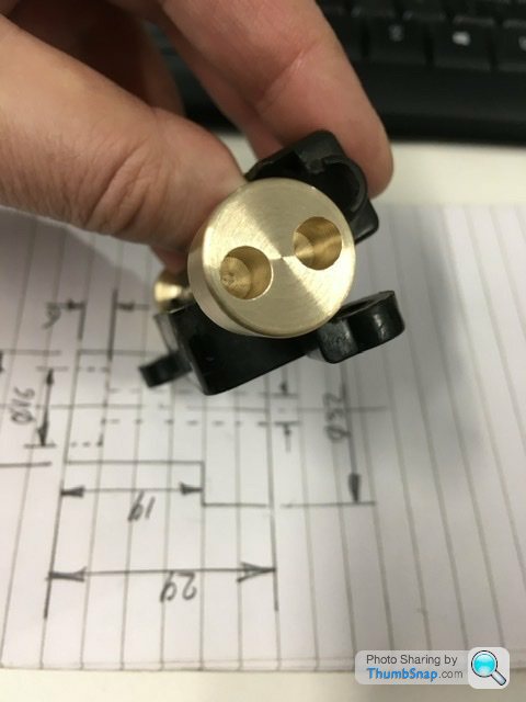
More bits I’ve made. This is the fuse between the battery and fuse box feed. Originally fed by two rather thin cables. Which I think would melt before blowing that 80amp fuse. Anyway made these brass cable terminals to use 2 8awg cables. I thought about a single 4awg but that isn’t rated for 80amps. Two 8awg cables are on the limit for 80amps. Better than original if still marginal.
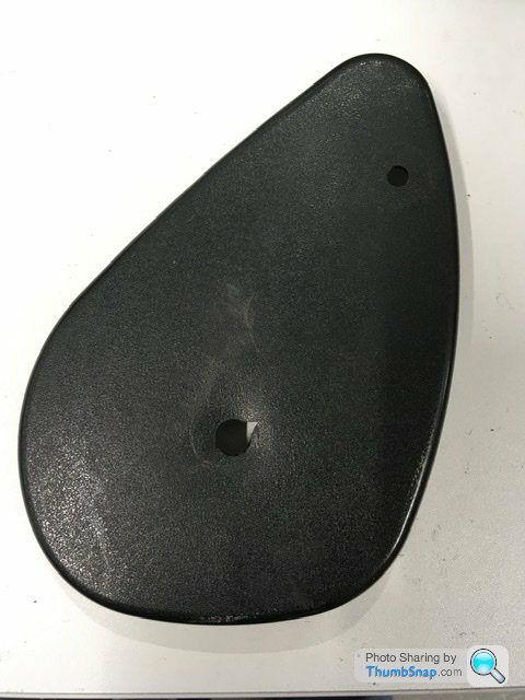
Above is one of the trims that fits the standard Griff seats. Broken as removed by the specialist tvr restorer. I’m sure I would have noticed these rattling around the seat but obviously I must have been mistaken.
So a repair is needed for both of them.
I made these oversized to cover the split in the plastic. One version is screwed on the slightly smaller diameter is I think is a push fit. I can’t be sure until the seats are back together. I think if I cover these trims in a bit of matching leather and then polish the aluminium bits they will look TVR.


RichB said:
RobXjcoupe said:
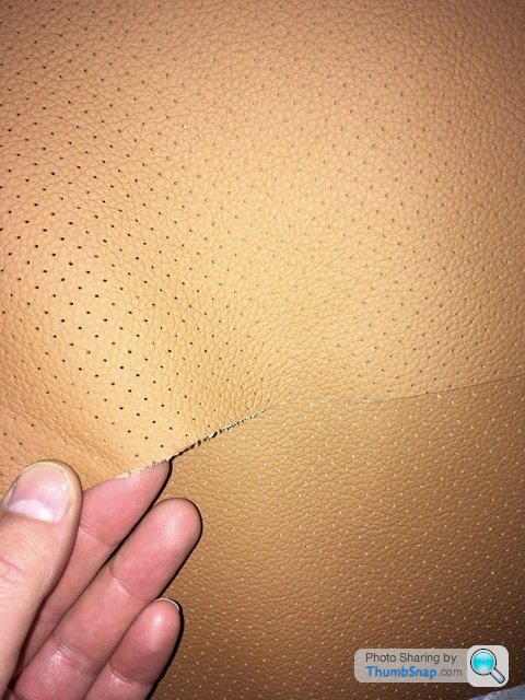
This evening the new leather hides finally arrived. The perforated leather looks good so worth the wait.
I’ll start the interior once the wiring is complete
Where are you using the perforated leather Rob? I’ll start the interior once the wiring is complete
Rather fancy that on the door cards in mine but as I'm really happy with the rest of the interior leather it would have to match the saddle colour perfectly else it would look odd. I ordered carpet door inserts when I bought the car and I was pleased with it because it's more comfortable when wearing a short sleeve shirt on long sweaty drives like at Le Mans but there's no doubt leather looks better.
I personally found the carpet a bit itchy on my arm/elbow but that’s not to say carpet is bad or not.
Regarding matching, I doubt it would unless you have the same batch used saved somewhere and even that may be different if the car has seen a few years of sun.
I thought use the perforated leather within the seat and bolsters with matching areas on the doorcards and the rear parcel shelf. Fingers crossed it should look lovely with black floor carpet…..not quite ready to start the interior just yet as I want the car running first after the wiring mods
Polly Grigora said:
Thank you.I never seem to find the correct sized cable terminals. Either too big for the cable but fit the battery or vice versa. So I make them using bits of otherwise scrap brass bar.
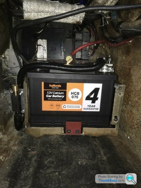
This takes time removing, measuring, cutting and soldering. So now have the new link from the battery to the main fusebox 80amp fused supply. Using the original 80amp fuse holder now bolted to a bracket attached to the battery box. Something else properly secured in a place of access.
Had a measure of the loom to the fusebox and I’m cutting 900mm off the length. Probably remove 1000mm but would require more mods to the loom elsewhere. A little extra isn’t a bad thing as the glovebox obviously moves open and shut with the loom so I don’t want it too tight it starts straining the wiring.
At the bottom of the above picture you can see a ring of silver/grey tape around the fusebox loom, that’s where it’s being cut to shorten it
lancepar said:
RobXjcoupe said:
Nice fix Rob.If peeps need any they and the tilt mechanism were from the Fiat X-19, I got some used ones off ebay.
They can also be obtained in GRP and 3D printing.

Gassing Station | Griffith | Top of Page | What's New | My Stuff