Need a circuit diagram...
Discussion


There are some things I just can't do. Languages is one, wiring diagrams is another.
This is the problem; can someone kindly post an idiot-proof answer, preferaby a diagram?
Q1: Captain Simpo has a boat with a heating system that uses a controller and a temperature sensor in the saloon. The two are connected by two-core cable. He wants to fit a second temperature sensor in the engine bay, and be able to select which sensor is operative with a two position switch marked 'Engine Bay/Saloon'. Only one sensor will be used at any time. The switch will need its own cable as it's not possible to wire both sensors directly to it.
He thinks he needs a DPDT switch - but got as far as 8 pencil lines all heading together then got stuck... [50 marks]
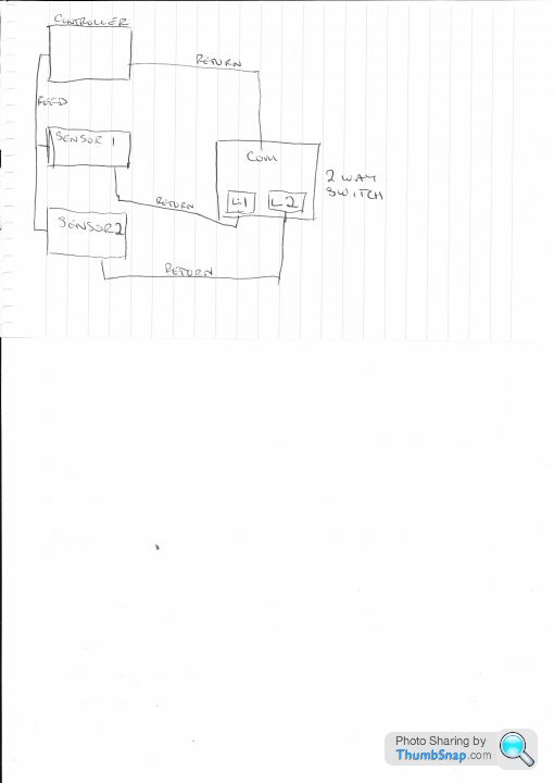
Can you identify the feed to the sensor, if yes then you could feed power to both sensors at the same time and just switch the returns from the sensors via a common two way switch. Return from sensor 1 to L1 return form sensor 2 to L2 and then connect the common back to the controller.
Edited by netherfield on Tuesday 12th February 14:08
http://www.maplin.co.uk/weathersafe-single-gang-2-...
This may do the job then!
There are plenty of toggle switches available online some with spade terminals, some with solder terminals.
The only Eberspacher I ever worked on was about twenty years ago, fitted as a night heater in a truck cab, no electronics or PCBs and just had a common central heating stat in the cab to control the temperature.
Looking at tha wiring diagrams has not helped either, although it does show the sensor having brown and white wires, as long as the polarities are kept right I can see no reason why it won't work.
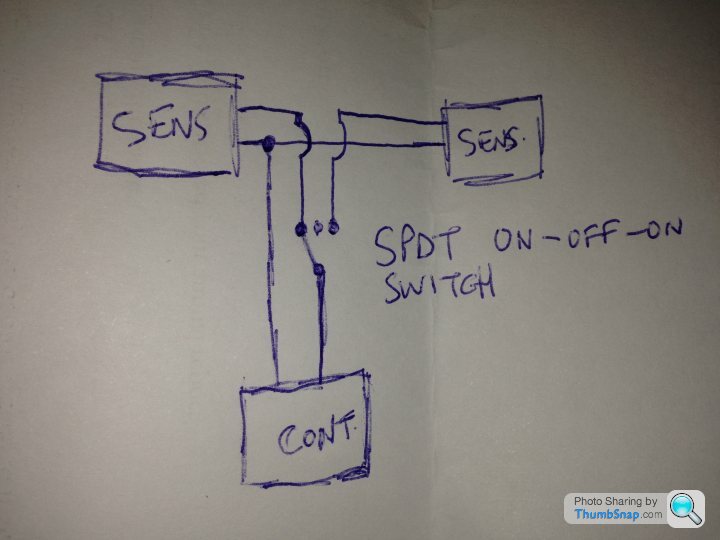
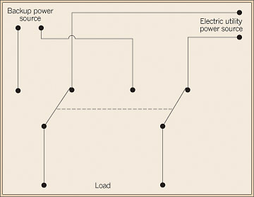
Diagram from google images.
Each mentioned power source would be the sensors
Load would be the controller.
Could really do with seeing the terminations on the switch to help more.
I searched Google for a 'Double pole 2 way switch' , the one from Maplin is also found on Amazon and Ebay.
Edited by netherfield on Thursday 14th February 11:59
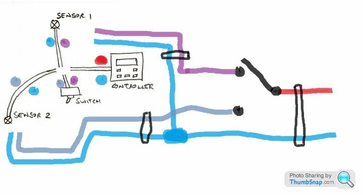
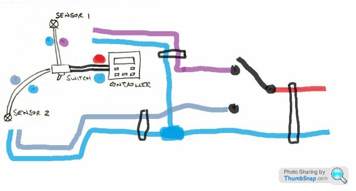
Thanks for the ideas so far... it might help if we start with what's facing me... this is how it looks:

'Feeds and returns' is getting too complex for my liking (I don't know which is which and the electronic controller might get confused by spare wires hanging about). Hence my desire to switch both wires. I think a DPDT switch has six pins.
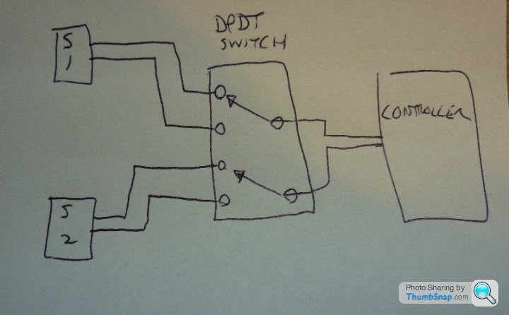
As you can see I just need to cross the hole in the middle
'Feeds and returns' is getting too complex for my liking (I don't know which is which and the electronic controller might get confused by spare wires hanging about). Hence my desire to switch both wires. I think a DPDT switch has six pins.
As you can see I just need to cross the hole in the middle

eliot said:
The drawings are correct. o/p the reason you are struggling is that you only have two wires from your switch - for any of the suggestions to work, your switch needs to be located where all your wires converge or you need extra wires leading to your switch location.
That's it exactly - the sensor wires (would) converge in an area under the helmsman's seat which is inaccessible. The physical layout side of it is actually very tricky, and not something I can easily convey!h8tax said:
The diagrams by HaplessBoyLard and Smiler are correct - unfortunately the one by ctdctd wont work (sorry - unless I am missing something?)
Doh - indeed it wouldn't. Swap the two inner connections to the sensors.Simpo, why not put the switch where all the wires end up - it's not as though it will get used a lot?
Simpo Two said:
That's it exactly - the sensor wires (would) converge in an area under the helmsman's seat which is inaccessible. The physical layout side of it is actually very tricky, and not something I can easily convey!
Got another idea for you then. Use a double pole double throw relay - which you wire up as shown above where your wires convergge. And then you use your switch with the two wires to simply turn the relay on and off.
If the relay needs to be in the energised position for hours or days, then you might want to consider a volt-free/latching relay instead.

Edited by eliot on Saturday 16th February 09:40
Gassing Station | Homes, Gardens and DIY | Top of Page | What's New | My Stuff