What´s that .... ?!
Discussion


Kind regards back JimmyZZ & Nick ! You are welcome !
Congratulation "m4tti" with 90% right.
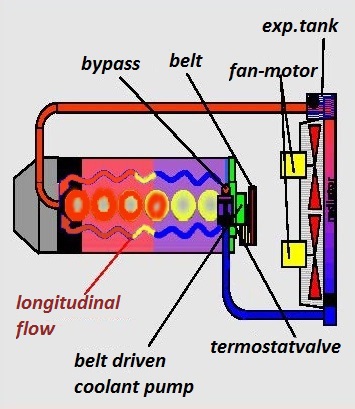
Here the problem
and here the better solution
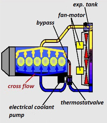
temperature-stabilized in all speed range optimized the engine temperature profile for a
better and longer life, better mapping , more power, less consumption ......
Kind regards
Gregor
Congratulation "m4tti" with 90% right.
Here the problem
and here the better solution
temperature-stabilized in all speed range optimized the engine temperature profile for a
better and longer life, better mapping , more power, less consumption ......
Kind regards
Gregor
Edited by vaurien on Tuesday 7th June 10:45
Yes we made kit´s for Rover V8 and TVR S6 engine still now and install.
http://www.pistonheads.com/gassing/topic.asp?h=0&a...
Later follow AJP8 and other engines too.
Regards
Gregor
http://www.pistonheads.com/gassing/topic.asp?h=0&a...
Later follow AJP8 and other engines too.
Regards
Gregor
I'm struggling getting my head around this so bear with me.
Are you sending the cold water into the block on the induction side and out of the head on the exhaust side? It *looks* like the exit water is coming lower than the head face, and that's no good unless you've worked out some way to weld shut the two lateral coolant transfers at the front and back of the engine. There are no transfers in the block other than the very front and back, but the head has coolant flow laterally between every chamber.
You sound a clever cookie so presumably you realise that your first picture doesn't actually represent the coolant flow through the sp6 engine.
The only way I can see this working is the water going in to the block and out of the head , with the ports centrally located longitudnally as you have in the second picture, and with the head gasket holes small in the centre and larger towards each end of the engine to try and maintain some evenness to the flow.
Because of those two large cross-block coolant ports at the front and back the water has to go in the block and out of the head for it to work at all. If they both port into the block you'd get next to no flow through the head without blocking the front and rear channels
spitfire4v8 said:
good luck with that then ..
So on your schematic your cold feed goes in via the core plug on the throttle body side? But in your pic the pipe around the head is connected to that collector on the output side where it would usually go to the heater. Or is that the way the pic has been taken. The Mechanical Water Pump is one of the last mechanical components of the modern engine which has long been considered an inefficient component that was designed as an accessory from the ever first engines. A mechanical belt driven pump installed on your car engines runs at the same speed as the engine regardless of how hot the engine is. Example: when travelling at high speeds down the freeway, the engine require less cooling as ram air is naturally cooling the engine however, the engine speed is high as is the mechanical water pump thus providing excessive cooling whilst draining the engine of power. Then in heavy traffic in high ambient, the engine is idling or slow and so is the belt driven mechanical pump, even though in this condition, extra coolant flow is required to cool the engine.
With an EWP and a digital controller, the speed of the pump is managed by the controller, which varies the supply voltage to the pump and so varies the speed of the pump, hunting for a target temperature. When the engine reaches the target temperature the controller locks on, constantly changing the pump speed with traffic and throttle conditions, maintaining the target temperature independent of the engine speed.
The important improvement for your vehicle comes from the fact that most of the power the mechanical pump takes from the engine can be reclaimed with the use of an ele.water pump hence the fuel savings. By removing the parasitic power losses of belt-driven water pumps, the ele.water pump may provide up to 10kw of extra power and additional fuel savings. The engine power used by the mechanical pump increases as the cube of its speed – so when the mechanical pump speed doubles from idle speed say; 600rpm to 1200 rpm, the power it takes increases by eight times. Then another eight times going to 2400 rpm, and so on up to maximum engine speed. It is this extra power and torque that is released by deleting the mechanical pump that provides the fuel savings that is estimated to be 3.5% to 10%.
Or take a look for this file too ......
https://drive.google.com/file/d/0B3l0goGWl5mZX1Q3d...
Kind regard
Gregor
Edited by vaurien on Friday 10th June 14:15
Sorry,
the download link was not working
https://drive.google.com/file/d/0B3l0goGWl5mZX1Q3d...
Regards
Gregor
the download link was not working
https://drive.google.com/file/d/0B3l0goGWl5mZX1Q3d...
Regards
Gregor
Gassing Station | Speed Six Engine | Top of Page | What's New | My Stuff