Mk1 Heater control ECU missing R4
Discussion


My car is a mk1 Tuscan from 2000 and I'm trying to get the aircon working again.
So far, the AC clutch engages with 12V directly applied either at the feed to clutch or via pin 13 on the heater control cable with the heater control unit removed.
There's 12V on both tabs of the thermal control relay in the passenger footwell and I've checked the trinary switch works ok (after a few taps on top). I do need to install a new plug/socket for the trinary switch as the original ones are a touch too corroded to make a consistent contact.
The problem I've come across is with the aircon request and acknowledge 12V in the heater control unit. I always have 12V on pin 7 (white/black) AC req and 12V on pin 19 (white/black) AC ack. This is with both the AC switch depressed or not. No 12V goes through to pin 13 (white/green) AC Clutch to activate the clutch. I'm not sure if I need the engine running for this anyway.
Is it correct that I need pin 19 to be dragged down to ground to put 12V onto pin 13 via a relay? Currently pin 13 seems to be held at ground at all times.
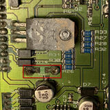
Last night I opened the heater control unit and found that R4 is missing which goes across one of the 1000uF capacitors. See below for some pics of my mk1 ECU.


I'm assuming this part of the AC circuit is not working due to this fault. The rest of the heater unit does work controlling the fan speed and loosely speaking the temperature (hot or hotter).
Could someone please let me know the value of R4? Otherwise I'll have to find a specialist to repair. A close up pic of the someone's circuit board would help as the value is written on the top of the resistor in very small print. I'm hoping it's a common surface mount value and I've looked in the case but it is long gone. Maybe it dropped off due to a dry joint and corrosion over the years as the PCB doesn't look too damaged in that area. You can see the indentation in the solder pads for the resistor. I've checked the diodes and they're OK but is there anything else that I could check to troubleshoot the AC part of the circuit?
So far, the AC clutch engages with 12V directly applied either at the feed to clutch or via pin 13 on the heater control cable with the heater control unit removed.
There's 12V on both tabs of the thermal control relay in the passenger footwell and I've checked the trinary switch works ok (after a few taps on top). I do need to install a new plug/socket for the trinary switch as the original ones are a touch too corroded to make a consistent contact.
The problem I've come across is with the aircon request and acknowledge 12V in the heater control unit. I always have 12V on pin 7 (white/black) AC req and 12V on pin 19 (white/black) AC ack. This is with both the AC switch depressed or not. No 12V goes through to pin 13 (white/green) AC Clutch to activate the clutch. I'm not sure if I need the engine running for this anyway.
Is it correct that I need pin 19 to be dragged down to ground to put 12V onto pin 13 via a relay? Currently pin 13 seems to be held at ground at all times.
Last night I opened the heater control unit and found that R4 is missing which goes across one of the 1000uF capacitors. See below for some pics of my mk1 ECU.
I'm assuming this part of the AC circuit is not working due to this fault. The rest of the heater unit does work controlling the fan speed and loosely speaking the temperature (hot or hotter).
Could someone please let me know the value of R4? Otherwise I'll have to find a specialist to repair. A close up pic of the someone's circuit board would help as the value is written on the top of the resistor in very small print. I'm hoping it's a common surface mount value and I've looked in the case but it is long gone. Maybe it dropped off due to a dry joint and corrosion over the years as the PCB doesn't look too damaged in that area. You can see the indentation in the solder pads for the resistor. I've checked the diodes and they're OK but is there anything else that I could check to troubleshoot the AC part of the circuit?
PS Electronics replied to my query and R4 is generally removed during any refurbishment. Apparently it's not required and it was a bleed resistor to stop the capacitors holding charge but they discharge through the blower motor regardless.
Anyway, my unit is faulty and will be sent off during the winter for refurbishment. Both PS Electronics and Motaclan (ex TVR Parts) can fix these mk1 units.
Anyway, my unit is faulty and will be sent off during the winter for refurbishment. Both PS Electronics and Motaclan (ex TVR Parts) can fix these mk1 units.
I'll keep the updates coming as other people may find this info useful in the future.
More wiring checks confirm that pin 7 connects through to pin 19 via the trinary switch. I was originally using info posted about the Cerbera aircon system and that car uses a different heater control unit and the aircon signal goes via the ECU. So the Tuscan seems to have a simpler aircon wiring layout.
https://www.pistonheads.com/gassing/topic.asp?h=0&...
I improvised applying 12V to the white/green wire of pin 13 with the pin removed from the plug. At work we used to use these Qikmate connectors a lot back in the 1990s so I have a de-pinning tool and odd connectors and pins from scrap bits of kit. I used a fuse jumper using the heater control unit fuse point (no 28 on the fuseboard) with a 3A fuse and a simple toggle switch to apply/remove the 12V. This let me test the clutch worked from inside the car. I then checked the compressor turned over freely by hand.
Moment of truth - started the car and then flicked the switch. Clutch engaged OK. Only did it for a few seconds, checked the belt and compressor were still OK and then engaged the clutch again. Noticed the fan came on for a few secs and then went off again but the car was warm from commuting back from work earlier. Took the plunge and left the car running with the aircon clutch engaged and I started to get cool air from the steering wheel vents. Progress! I was getting warm air from the screen vents so I know I need to investigate my heater flap stepper motor as that probably isn't working. Maybe that failed and blew the control unit? Anyway, I didn't have the car running long but I know my car holds aircon gas, the trinary switch works, the clutch and compressor work, the wiring to and from the engine bay works.
Next can I have a go at fixing the heater control unit myself? To be honest these electronics are pushing my knowledge especially the surface mount components and I haven't studied electronics since the 1990s either.
I have been making some passive tests in the evenings using my limited knowledge and here are some of my findings. Again they might be useful to others in the future. The control unit is easy enough to open and close up so it isn't a problem testing a few things and then putting it back together so that I continue to have a functioning car.
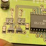
Here are some of the components present. I won't go through all of them but this is just a write up of my notes of the ones I thought worth while noting. There are one or two NPN and PNP transistors I didn't note and the obviously marked relay and ICs aren't noted below.
Diodes
Majority are Schottky diodes marked IR1F which I believe are 10MQ040 simple 1A 40V rated.
Diodes marked A7 in SMD SOT-23 probably something like a BAV99

Other
U4 marked 811B might be DS1811 5V monitoring IC
NPN transistor FZT651 driving the relay
LM2931 voltage regulator (hard to photograph)
MOSFET VNP35 (VNP35N07-E)
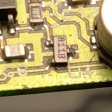

At the moment it looks like by two NPN transistors which drive the relay (V23084-C2001-A303) have died as base-collector is short and base-emitter is open. The diode across the relay coil threw me originally as it was reading ~0.1V using the diode function on my meter both ways (forward and reverse bias) which apparently is OK taking into account the coil and measuring in-circuit plus it is a Schottky diode. If I apply 12V briefly across the coil pins in a forward bias direction and the relay operated OK. That was for both coils.
Next step is to investigate the 2 NPN transistors more and my stepper motor, check that is all OK. Fingers crossed the stepper motor IC is OK as it isn't easily available in the surface mount format anymore.
More wiring checks confirm that pin 7 connects through to pin 19 via the trinary switch. I was originally using info posted about the Cerbera aircon system and that car uses a different heater control unit and the aircon signal goes via the ECU. So the Tuscan seems to have a simpler aircon wiring layout.
https://www.pistonheads.com/gassing/topic.asp?h=0&...
I improvised applying 12V to the white/green wire of pin 13 with the pin removed from the plug. At work we used to use these Qikmate connectors a lot back in the 1990s so I have a de-pinning tool and odd connectors and pins from scrap bits of kit. I used a fuse jumper using the heater control unit fuse point (no 28 on the fuseboard) with a 3A fuse and a simple toggle switch to apply/remove the 12V. This let me test the clutch worked from inside the car. I then checked the compressor turned over freely by hand.
Moment of truth - started the car and then flicked the switch. Clutch engaged OK. Only did it for a few seconds, checked the belt and compressor were still OK and then engaged the clutch again. Noticed the fan came on for a few secs and then went off again but the car was warm from commuting back from work earlier. Took the plunge and left the car running with the aircon clutch engaged and I started to get cool air from the steering wheel vents. Progress! I was getting warm air from the screen vents so I know I need to investigate my heater flap stepper motor as that probably isn't working. Maybe that failed and blew the control unit? Anyway, I didn't have the car running long but I know my car holds aircon gas, the trinary switch works, the clutch and compressor work, the wiring to and from the engine bay works.
Next can I have a go at fixing the heater control unit myself? To be honest these electronics are pushing my knowledge especially the surface mount components and I haven't studied electronics since the 1990s either.
I have been making some passive tests in the evenings using my limited knowledge and here are some of my findings. Again they might be useful to others in the future. The control unit is easy enough to open and close up so it isn't a problem testing a few things and then putting it back together so that I continue to have a functioning car.
Here are some of the components present. I won't go through all of them but this is just a write up of my notes of the ones I thought worth while noting. There are one or two NPN and PNP transistors I didn't note and the obviously marked relay and ICs aren't noted below.
Diodes
Majority are Schottky diodes marked IR1F which I believe are 10MQ040 simple 1A 40V rated.
Diodes marked A7 in SMD SOT-23 probably something like a BAV99
Other
U4 marked 811B might be DS1811 5V monitoring IC
NPN transistor FZT651 driving the relay
LM2931 voltage regulator (hard to photograph)
MOSFET VNP35 (VNP35N07-E)
At the moment it looks like by two NPN transistors which drive the relay (V23084-C2001-A303) have died as base-collector is short and base-emitter is open. The diode across the relay coil threw me originally as it was reading ~0.1V using the diode function on my meter both ways (forward and reverse bias) which apparently is OK taking into account the coil and measuring in-circuit plus it is a Schottky diode. If I apply 12V briefly across the coil pins in a forward bias direction and the relay operated OK. That was for both coils.
Next step is to investigate the 2 NPN transistors more and my stepper motor, check that is all OK. Fingers crossed the stepper motor IC is OK as it isn't easily available in the surface mount format anymore.
Update - changed the two NPN transistors and now my AC clutch works. Air con circuit now all working fine. Some positive progress at last.
Opened up the heater matrix airbox cover and found my stepper motor actuator disconnected and the stepper motor incorrectly wired. Tested the motor is still ok using a simple 4 phase stepper driver from eBay. That checks out fine and I could identify the centretaps A1,B1,A2,B2 connections etc.
Next step is to work out if the PIC microcontroller is sending instructions to the stepper driver ok or if the stepper driver is dead. I suspect the driver is dead as all other controls work but I need to confirm.
Gassing Station | Tuscan | Top of Page | What's New | My Stuff