Electronic tech help please
Discussion


Right, all you techy elecy types, I can figure out most things, even down to component level but these little critters are confusing me. I know some clever people surf and even contribute so please help if you can.
I hope the pics have made it... this is always a problem for me.
History, HSV Maloo dash pod has brake warning light on, second pod doesn't but has fuel gauge issue... so I know wiring to dash/brake switch is not at fault, it is in the pod and I have shifted a permanent fault to a intermittent fault so we are winning there and with the new inspection lamp and magnifier I reckon the fault will soon be sniffed out, but what does severely piss me off is the speedo needle does not illuminate... it seems the PO (instructed others) to silence the warning buzzer, and in so doing the clumsy whoever managed to shave the SMDs off that drive the LEDs that illuminate the needle. umhhh.
I could desolder the devices from the second pod but that is not without risk and rather prefer to leave alone as I will track the fuel gauge fault in due course.
Who can help me identify the transistors and the resistors. And... where to buy a small novice type quantity ( like two of each) so I can use my low temp solder and digital soldering iron to fix my Maloo dash. I am old now and winter is here so chassis cleaning a TVR is a young persons job... I will retreat to the office with the soldering iron and a mug of tea.
TVRs are much easier... Thanks in advance if you can assist.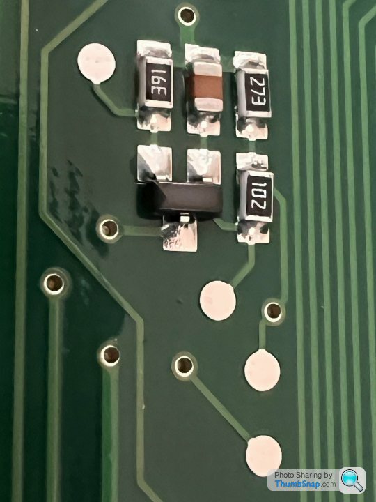 |https://thumbsnap.com/2UXG9T1m[/url] ,
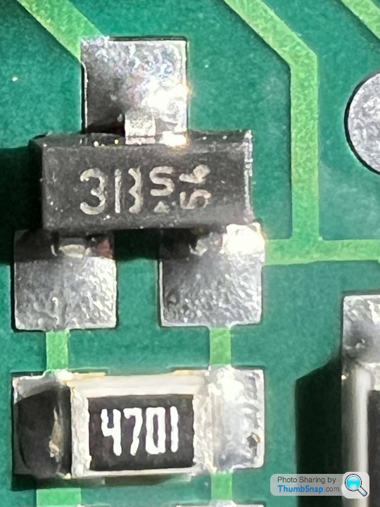 ,
,
I hope the pics have made it... this is always a problem for me.
History, HSV Maloo dash pod has brake warning light on, second pod doesn't but has fuel gauge issue... so I know wiring to dash/brake switch is not at fault, it is in the pod and I have shifted a permanent fault to a intermittent fault so we are winning there and with the new inspection lamp and magnifier I reckon the fault will soon be sniffed out, but what does severely piss me off is the speedo needle does not illuminate... it seems the PO (instructed others) to silence the warning buzzer, and in so doing the clumsy whoever managed to shave the SMDs off that drive the LEDs that illuminate the needle. umhhh.
I could desolder the devices from the second pod but that is not without risk and rather prefer to leave alone as I will track the fuel gauge fault in due course.
Who can help me identify the transistors and the resistors. And... where to buy a small novice type quantity ( like two of each) so I can use my low temp solder and digital soldering iron to fix my Maloo dash. I am old now and winter is here so chassis cleaning a TVR is a young persons job... I will retreat to the office with the soldering iron and a mug of tea.
TVRs are much easier... Thanks in advance if you can assist.
|https://thumbsnap.com/2UXG9T1m[/url] , ,SMD resistors are usually identified by two digits giving an ohms resistance and a third digit giving the number of zeroes. For example 273 indicates 27000 Ohms (27KOhms).
SMD capacitors typically use a similar scheme to indicate the capacitance in picoFarads.
If you want to unsolder them, use a hot air soldering gun, the right flux and cleaning agents, together with tweezers and a magnifying glass, With the right gear and technique it's quick and easy.
It isn't always obvious which are capacitors and which are resistors but you can probably work it out from the circuit design once you have worked that out. For example, a component spanning two power rails is probably a capacitor but a component in series is more likely to be a resistor.
Your best bet to identify the transistor - if that's what it is - is to work out the voltage and polarity from the circuit design and guestimate the current rating.
Hi John
So the resistors are easy. 3 digits = 5% in decades and last digit is power of 10. So 391 (NOT 16E!) is 3 9 x10^1 so 390 ohms. 4 digit ones are 1% in same scheme but one more decade is defined so 4701 is 4 7 0 x10^1 i.e 4700 ohms.
The transistros can be little buggars.
Try this little beauty of a page...
https://smd.yooneed.one/code3342.html
So your 1B is prob a BC846
3B prob BC856
hth
PetrolHeadPete said:
Hi John
So the resistors are easy. 3 digits = 5% in decades and last digit is power of 10. So 391 (NOT 16E!) is 3 9 x10^1 so 390 ohms. 4 digit ones are 1% in same scheme but one more decade is defined so 4701 is 4 7 0 x10^1 i.e 4700 ohms.
The transistros can be little buggars.
Try this little beauty of a page...
https://smd.yooneed.one/code3342.html
So your 1B is prob a BC846
3B prob BC856
hth
Thanks Pete, So the resistors are easy. 3 digits = 5% in decades and last digit is power of 10. So 391 (NOT 16E!) is 3 9 x10^1 so 390 ohms. 4 digit ones are 1% in same scheme but one more decade is defined so 4701 is 4 7 0 x10^1 i.e 4700 ohms.
The transistros can be little buggars.
Try this little beauty of a page...
https://smd.yooneed.one/code3342.html
So your 1B is prob a BC846
3B prob BC856
hth
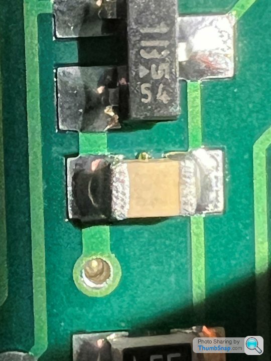
Reading the SMD code book I think I am understanding the arrow under the small 's' indicates lower case, which helps narrow it down. The 3B on it's own could be NPN or PNP but the 's' closes out the uncertainty on that. Not sure the '54' is anything important, so need to find a supplier now. What is still at large is the identity of the unmarked components, are they capacitors??? There are two different colours but no numbers or letters.
All this so I can see how fast I am going at night, any why do manufacturers make it so complicated. The Jag has bulbs, tiny little screw in jobbies that fizz n fuzz out and then snap off and cut my fingers as I unscrew them but at least I can see what's wrong and sort it, this is space age for me.
Be easier to buy a new car but the journey is the best bit....
The brown ones are caps. 99.9999% they wont have failed so you should discount those. The R's prob havent failed either. Normally they'd be burnt and all look ok to me. You might be able to DMM them in circuit on ohms but dont totally expect sensible answers due to other circuit elements being in parallel. But, can give you some guidance if they are ok or not (especially lower values like 100's of ohms...they tend to dominate so can be measured)
You can prob get all you need from farnell.
You can prob get all you need from farnell.
Pete, the problem is the components are missing. When the original fault manifested the OP instructed a heavy handed clown to silence the alarm buzzer, he did this without care and shaved off the transistor, one capacitor and a couple of resistors local to the sounder... Great. I know this as I have another dash pod with the components where my current one has intact, previously soldered, pads.... I could desolder and transplant but that ruins the spare dash that despite having a fault is ripe for repair so prefer not to mess with that, even though the repair seems more involved on that one.
The capacitor I will need to meter this to determine its value as no markings apparent. The rest of the components are identified now.
Thanks again for your help, cheers J
The capacitor I will need to meter this to determine its value as no markings apparent. The rest of the components are identified now.
Thanks again for your help, cheers J
Caps can sometimes be measured in-situ (assuming you have C on your DMM). Worth a try...may give you a clue. They are never marked btw, no idea why! If that's a simple switching circuit i'll bet its going to be in the 1nF to 100nF range. Its a cermaic type BTW.
You might get away replacing just the Rs and TRs and leave the cap out to start with. Often they are just used as a bit of smoothing on power supplies.
Worth a shot.
You might get away replacing just the Rs and TRs and leave the cap out to start with. Often they are just used as a bit of smoothing on power supplies.
Worth a shot.
Gassing Station | General TVR Stuff & Gossip | Top of Page | What's New | My Stuff