2.9 Cooling System
Discussion


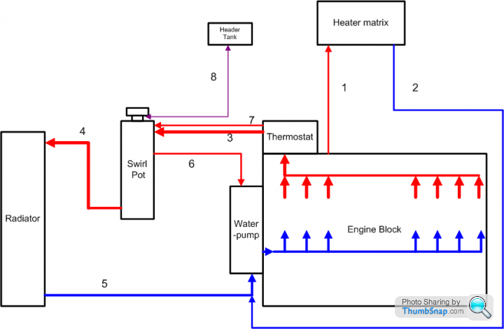
There seems to be this idea that blocking or restricting one of the pipes in the cooling system fixes a design flaw in the cooling system on the 2.9 S. The engineer in me didn't really want to go fiddling without understanding exactly what I was doing so I have mapped out the cooling system as accurately as i could but I still can't figure it out so I thought I'd post it up here for comments.
Sorry the drawing is a bit crude but it's only a free drawing app I found quickly.
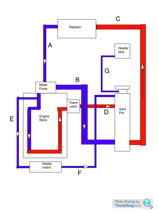
The pipes are correct although the flow directions are a bit of a guess, especially pipe B. Pipe B is the convoluted one that goes over the fan belt by the alternator and is the pipe that it is suggested is blocked off I believe. Also pipe D is actually 2 pipes, I'm assuming the main outlet from the thermostat and a smaller bypass hose.
I don't understand pipe B as it seems to be a radiator bypass that isn't regulated at all. The flow direction on B is a guess from where it is positioned on the water pump but it makes no sense. Surely it should be temperature controlled so when the engine is cold pipe B is used and the radiator is bypassed, when the engine is warm pipes A and C are used and B is blocked so the water is cooled.
It would be nice to get this sorted so there is a reference for the cooling system should anyone want to fiddle with it.
Sorry the drawing is a bit crude but it's only a free drawing app I found quickly.
The pipes are correct although the flow directions are a bit of a guess, especially pipe B. Pipe B is the convoluted one that goes over the fan belt by the alternator and is the pipe that it is suggested is blocked off I believe. Also pipe D is actually 2 pipes, I'm assuming the main outlet from the thermostat and a smaller bypass hose.
I don't understand pipe B as it seems to be a radiator bypass that isn't regulated at all. The flow direction on B is a guess from where it is positioned on the water pump but it makes no sense. Surely it should be temperature controlled so when the engine is cold pipe B is used and the radiator is bypassed, when the engine is warm pipes A and C are used and B is blocked so the water is cooled.
It would be nice to get this sorted so there is a reference for the cooling system should anyone want to fiddle with it.
phillpot said:
Good effort Tom but at a quick glance F doesn't look right ?
I think F is the pipe that turns into a steel pipe that runs along the underside of the engine then pops out at the front somewhere. It's a little difficult to trace with the engine in and it pops into the block at the end I think but that's where it seems to go. I always assumed the heater matrix would get water from the hot output from the engine. Saying that I could have just got it wrong!Sighck: The file is from a Mac program called Drawberry. It's a simple vector graphics drawing program so another vector graphics package may be able to edit it. I'll PM it to you though so you can have a play.
Tom
Thanks for the comments, right version 2...
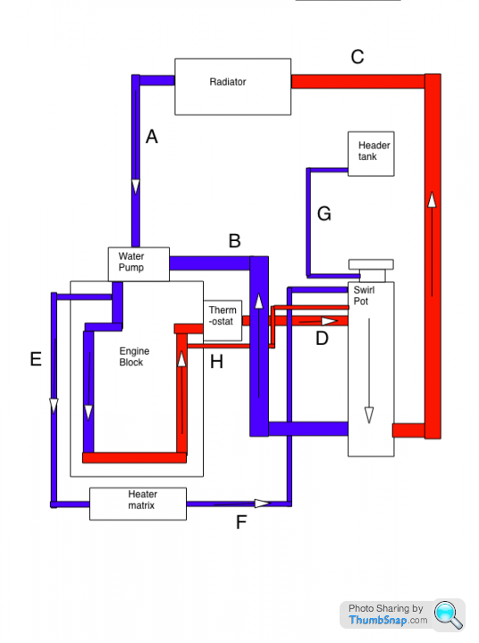
I've switched the direction of B and added H which is the thermostat bypass. I tried adding a swirly arrow in the swirl pot but my artistic skills aren't up to it!
Looking at that diagram assuming it is correct then the thermostat shouldn't be on the engine but should be on the swirl pot outlet and should either divert water to the radiator or back to the water pump. ie if the engine is cold the water should go down B to the water pump, and if the engine is warm it should go down C. Lots of ideas for rerouting the cooling system are popping into my head now!
If anyone has any other corrections I'll add them.
Sighck: I can't PM attachments so I have PM'ed you so you can reply and I can send the file.
Scoobimax said:
And once you've sussed out the flow, perhaps you can tackle where the pressure cap goes and the blanking cap?
I'll get me coat........

I don't think we should get into that again even if we get this cooling system sussed!!I'll get me coat........
HvdWeerden said:
And then explain why the heater matrix gets cold water ?
Well cold is a relative term but your right it would make morse sense to take the water that has just got heated up by the engine. The outlet from the engine could be anywhere in the cooling loop though as it comes out the block I think so it could be later in the loop.AutoAndy said:
...looking forward to seeing this resolved. Forget the search for Nessy, bigfoot, Higgs Boson, or the source of S indicators, this is the big one.
I have not got anything useful to add now, but will throw my threepenny's worth in if I can. Good luck with it Tom, I know you have the engineering dedication of a rottweiler hanging onto a postmans leg...I just hope you can sort it before it takes over your life, your living room wall, and your sanity.
So does my wife!I have not got anything useful to add now, but will throw my threepenny's worth in if I can. Good luck with it Tom, I know you have the engineering dedication of a rottweiler hanging onto a postmans leg...I just hope you can sort it before it takes over your life, your living room wall, and your sanity.
I've had a break from fiddling with the TVR for a while but now I am planning cold air intakes, pedal improvements and cooling system modifications! The worrying thing is this is what keeps me sane

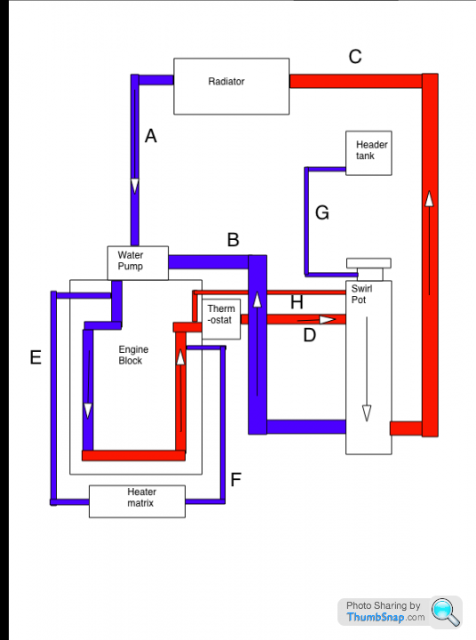
Mike your right, had a closer look at the heater circuit and I think it is a little closer to the truth now although I don't think it is completely right. I have no idea what the flow direction is but E seems to be close to the water pump I think, its a little difficult to see. The colours for E and F are probably wrong but I'll fix them when I figure out the routing for certain.
Take 3...
Take 3...
techbotics said:
where does the hot water from the bloc go with the stat closed?
Damian
I think the idea is that the tiny pipe H stops the pressure getting too high and keeps a little water flowing round the block so it doesn't boil in the heads but basically the thermostat stops the water circulating.Damian
That would mean though that as soon as the thermostat opens the block which has nice hot water in it probably gets a big lump of cold water which the engine then has to heat up.
At the moment I can't figure out why blocking B off would give faster warm up times as has been reported. As I see it blocking B should force all the water through the radiator and make warm up take longer. It should however stop the car over heating which I think is a more common problem.
Mike sorry for getting in there ahead of you! I have wanted to put a diagram up for months but its taken me that long to find a program to draw the diagram in and actually draw it.
Hasse (sighck) has kindly constructed another diagram to correct my errors which happen to be exactly the same corrections that you just suggested Mark.
I've included mine and Hasse's diagrams for reference. Again comments welcome.
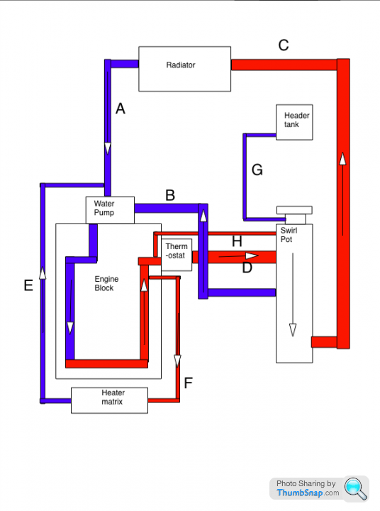
I think Hasse's diagram is neater and clearer but I'm including mine as well because it's mine
Hasse has also supplied a diagram of a modification he suggests to get the cooling system to work properly.
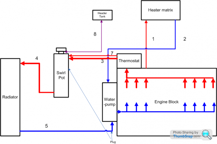
This involves removing 2(E) from the water pump end and plugging the hole. Removing 6(B) entirely and plugging the hole in the swirl pot. Rerouting the water pump end of 2(E) into the hole left at the water pump by removing 6(B).
I'm sure that will cause some arguments
I've included mine and Hasse's diagrams for reference. Again comments welcome.
I think Hasse's diagram is neater and clearer but I'm including mine as well because it's mine
Hasse has also supplied a diagram of a modification he suggests to get the cooling system to work properly.
This involves removing 2(E) from the water pump end and plugging the hole. Removing 6(B) entirely and plugging the hole in the swirl pot. Rerouting the water pump end of 2(E) into the hole left at the water pump by removing 6(B).
I'm sure that will cause some arguments
Thought I'd update things.
I put a brake hose clamp on pipe B(6) to stop water flowing through it a couple of weeks ago. The difference in temperature stability is noticeable as the temperature gauge now holds the needle horizontal no matter how I drive unless I stop in traffic. Then the needle rises until the fan comes on and it rapidly falls back to horizontal again. Compared with the needle moving around far more with B(6) unblocked and spending far more of its time above horizontal I would say that the pipe is definitely a hindrance rather than a help!
Now I just need to find an 18mm (I think thats the diameter) cap for the swirl pot and water pump....
Just bought 2 pairs (meant to buy 2 but apparently I can't read!) of these.
Hopefully they will make things look a little neater. I don't think it needs more flow than the thermostat bypass gives already. I opened the swirlpot when I started the engine and there is a pretty high flow even when the thermostat is closed.
Hopefully they will make things look a little neater. I don't think it needs more flow than the thermostat bypass gives already. I opened the swirlpot when I started the engine and there is a pretty high flow even when the thermostat is closed.
Gassing Station | S Series | Top of Page | What's New | My Stuff