Discussion


Further to the door hanging thread I thought this information might be useful to others and for future reference.
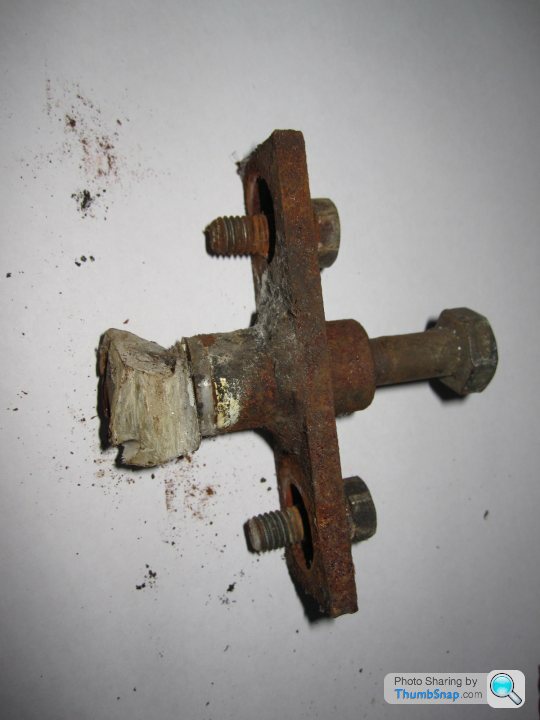
Complete upper hinge which was 'hacked' out of the body tub
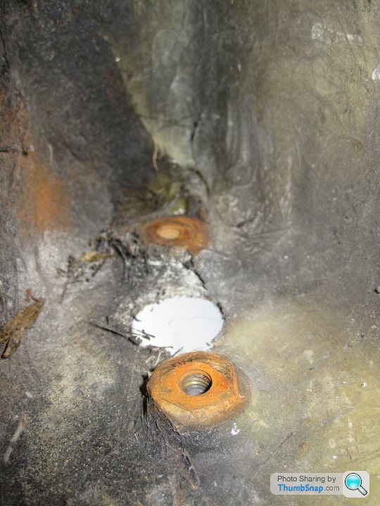
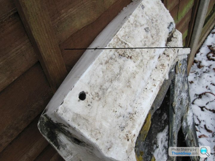
Bobbins inside the door
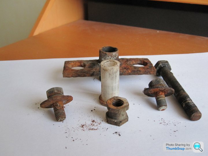
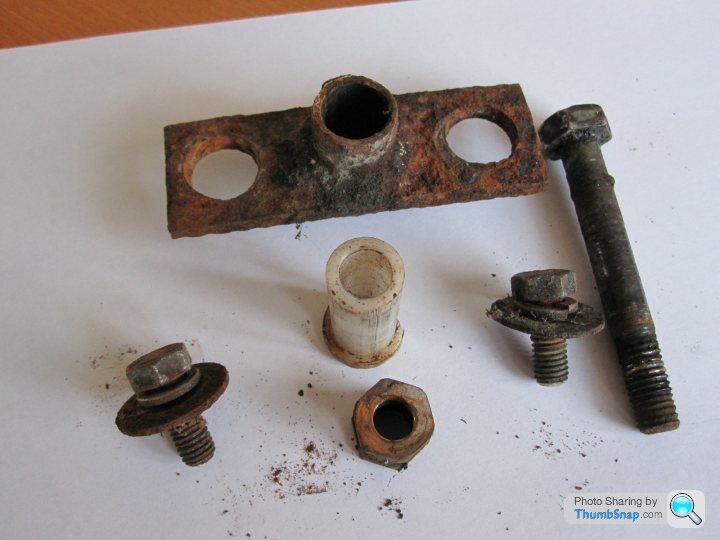
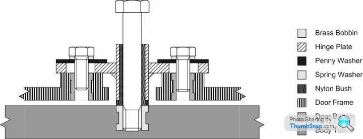
Exploded hinge
The M10 bobbins and the nylon 'top hat' bushes are available from TVR Car Parts. As I understand it the critical thing is to have the M10 hinge bolt tighten into the bobbin
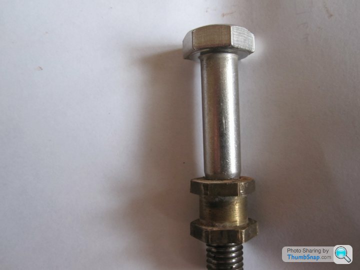
without any thread protruding, this is certainly so for the top hinge but possibly the bottom bobbin has a void below.
The unthreaded shank needs to be approx 52mm and the threaded length no more than 15mm, to achieve this you will have to have to cut down a longer bolt, probably 70 - 80mm overall length.
Earlier cars, possibly S1 but with TVR who knows, used M8 bobbins but neither they or the appropriate nylon bush is available. However the outside diameter of the both the M10 and M8 bushes are identical so as long as the bobbin glassed into the body shell is changed to an M10 earlier hinges can be reconditioned.
I have all the other dimensions if anybody would like them.
It does occur to me that replacement sets in stainless could be useful so if anyone is interested I could price up replacement sets. Obviously I would approach TVR Car Parts for bobbins/bushes.
This thread is also possibly useful http://www.pistonheads.com/gassing/topic.asp?h=0&a...
Complete upper hinge which was 'hacked' out of the body tub
Bobbins inside the door
Exploded hinge
The M10 bobbins and the nylon 'top hat' bushes are available from TVR Car Parts. As I understand it the critical thing is to have the M10 hinge bolt tighten into the bobbin
without any thread protruding, this is certainly so for the top hinge but possibly the bottom bobbin has a void below.
The unthreaded shank needs to be approx 52mm and the threaded length no more than 15mm, to achieve this you will have to have to cut down a longer bolt, probably 70 - 80mm overall length.
Earlier cars, possibly S1 but with TVR who knows, used M8 bobbins but neither they or the appropriate nylon bush is available. However the outside diameter of the both the M10 and M8 bushes are identical so as long as the bobbin glassed into the body shell is changed to an M10 earlier hinges can be reconditioned.
I have all the other dimensions if anybody would like them.
It does occur to me that replacement sets in stainless could be useful so if anyone is interested I could price up replacement sets. Obviously I would approach TVR Car Parts for bobbins/bushes.
This thread is also possibly useful http://www.pistonheads.com/gassing/topic.asp?h=0&a...
Edited by Gerald-TVR on Monday 2nd May 08:21
v8s4me said:
Sorry if I'm being thick, but are all these photos of the top hinge? I managed to take up some of the sag in my door by tweeking the nuts either side of the lower hinge bracket. The bolt in the top was very stiff and I din't want to force it in case it ripped itself out of the moulding so I left it alone. If the bolt in the upper hinge designed so that if you tighten it, ie turn it clockwise, it effectively pulls the dood up? Mine's still not quite perfect but I've been reluctant to push my luck any further. Thanks. Joe
The first is the top hinge and the exploded the lower but they are identical in all respects. The center bolt is just the hinge pin and tighten it will only serve to lock it tighter in the bobbin, unless you have more than 15mm of thread when it could just break through the painted area above the top hinge. As you can see the is a large, 20mm, gap between the head and the body of the hinge so when new (and not clagged and rusted up) the hinge plate would slide up and down the bolt shank. The only things that locates the door in the vertical are the top hat nylon bushes. If there is excessive plane up and down then I would guess that if the bushes were replaced that would remove the play. Or possibly adding new thin nylon washersv8s4me said:
If the bolt in the upper hinge designed so that if you tighten it, ie turn it clockwise, it effectively pulls the dood up?
No will NOT pull the door up, unless the bolt head is flush to the hinge plate and it isnt designed to be that way but possible I suppose it the wrong sort of bolt has been fitted.v8s4me said:
Mine's still not quite perfect but I've been reluctant to push my luck any further.
Wise movev8s4me said:
On mine (bottom) there is a nut on either side of the door plate so by slackening the upper nut and tightening the lower one I was able to lift the door and take out some of the sag.
Hi JoeSounds very different from what I thought the standard setup was. I would be very wary of tightening the top bolt because of the potential to crack through the body tub above the door but I guess there is a void below the lower bobbin. Would be very useful if you could take a photo the next time you have the door card off. Cant give you any other advice, sorry
Norman
Gerald-TVR said:
The unthreaded shank needs to be approx 52mm and the threaded length no more than 15mm, to achieve this you will have to have to cut down a longer bolt, probably 70 - 80mm overall length.
I have found out that an M10 bolt x 75mm long should have a shank of 49mm, which would be fine, and a threaded length of 26mm which would have to be shortned definatly for the top bolt and possibly for the lowerNorman
v8s4me said:
Brilliant drawing Norman. if this was the bottom hinge, would there be an adjusting nut on either side of the hinge plate? Thanks. Joe
No adjusting nuts at all on either top or bottom hinge, dont forget this is an S2 and itspossible that the S3 and later might differ. However i still have an S3 door (but not at home), when I get a chance I'll strip the hinges on that as well and check for differencestrevbeadle said:
So, my question.....
I have one of the early S1's so presume the nylon bush is an 8mm one which is apparently no longer available!
Is there any other options apart from changing the while issue to the later 10mm hinge setup?
Anyone tried removing the worn 8mm bush and re-sleeving it with something to take out the wear?
I know the external dimensions are the same with the 8 and 10 mm bushes (and length?), so how about using a new 10mm bush and fabricating a new bolt with a 10mm shank but an 8mm thread?
Trev
I havent seen a 8mm hinge so am not sure that the only differences are the bush and bolt however if that is the case then it would be easier to have a new bush turned in brass (say) than have new bolts made. But its possible you might be able to find a shoulder bolt on the electric interweb. Arian Venn Exactly TVR I know makes his own bushes if he is repairing/replacing a hinge. He's a very helpful chap why not give him a ringI have one of the early S1's so presume the nylon bush is an 8mm one which is apparently no longer available!
Is there any other options apart from changing the while issue to the later 10mm hinge setup?
Anyone tried removing the worn 8mm bush and re-sleeving it with something to take out the wear?
I know the external dimensions are the same with the 8 and 10 mm bushes (and length?), so how about using a new 10mm bush and fabricating a new bolt with a 10mm shank but an 8mm thread?
Trev
Edited by trevbeadle on Friday 25th February 10:03
trevbeadle said:
Gerald-TVR
you say in your opening post in this thread "However the outside diameter of both the M10 and M8 bushes are identical". If you can provide me with the dimensions of the bush, I have sourced nylon rod (as GreenV8S suggested) so could have a go at fabricating an 8mm internal bore one!
I was told that they were identical by someone I know and trust, if you drop me a PM I will send dimensions to you, also if you let me have your address I can let you have an old bush to look at. But as with all information please use at your qwn riskyou say in your opening post in this thread "However the outside diameter of both the M10 and M8 bushes are identical". If you can provide me with the dimensions of the bush, I have sourced nylon rod (as GreenV8S suggested) so could have a go at fabricating an 8mm internal bore one!
I'm delighted to say that I am still asked for some extra information regarding some of the drawings I prepared all those years (8 or so) ago. So I have been used some new knowledge learned recently to flesh out door hinges.
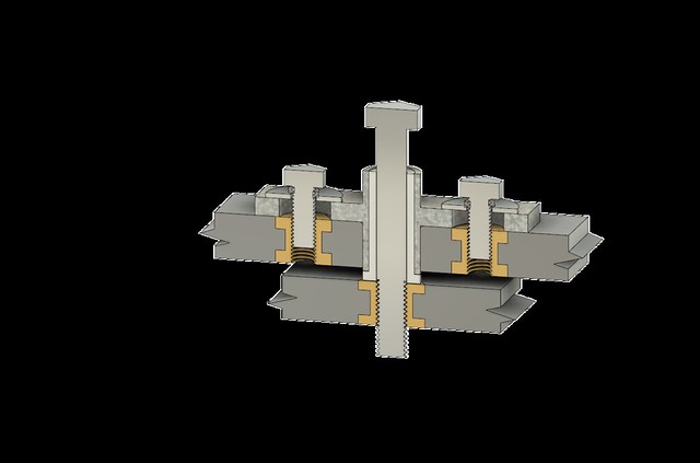
So below please find two extra, 3 D, drawings of the lower door hinge for an S2, hope they help! I will add the upper hinge tomorrow.
Norman
 TVR Door Hinge Assembled Sectioned v1 by nfarmer1, on Flickr
 TVR Door Hinge Assembled v5 by nfarmer1, on Flickr
So below please find two extra, 3 D, drawings of the lower door hinge for an S2, hope they help! I will add the upper hinge tomorrow.
Norman
TVR Door Hinge Assembled Sectioned v1 by nfarmer1, on FlickrTVR Door Hinge Assembled v5 by nfarmer1, on Flickr
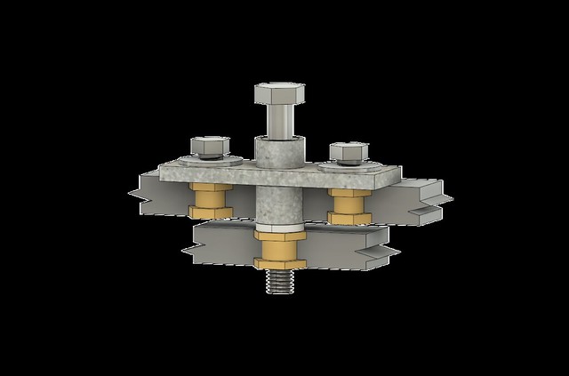
Upper hinge as promised note the lack of a void and the truncated thread length. Also Adrian Venn has reminded me that the lower hinge MUST bottom out on the bobbin and not the fiberglass of the body tub.
 TVR Door Upper Hinge Assembled Sectioned v1 by nfarmer1, on Flickr
TVR Door Upper Hinge Assembled Sectioned v1 by nfarmer1, on FlickrDamianS3 said:
Hello Norman
Are you using tinkerCAD or sketchup for those drawings?
Or something not free?
Cheers
Damian
Hi DamianAre you using tinkerCAD or sketchup for those drawings?
Or something not free?
Cheers
Damian
Edited by DamianS3 on Thursday 7th February 12:55
Fusion 360 is my software of choice, it would be prohibitive expensive but, bless Autocad, they allow a free licence for education or a hobbyist not working for profit.
It's a fantastic piece of software I only scratch the surface.
Regards Norman
Just to round it off I decided to create a physical representation of the lower hinge, (For the techies I used Fusion 360 for the design work Slic3r PE to slice the STL files and print the components in various shades of colour using PLA and the Prusa Mk2.5 printer.)
 IMG_3528 by nfarmer1, on Flickr
Norman
IMG_3528 by nfarmer1, on FlickrNorman
GreenV8S said:
It looks as if the physical model has the pivot bolt protruding out of the threaded bobbin. Isn't that hole blind in reality?
I believe there is a void below the bottom hinge but as the pivot bolt HAS to bottom out on the bobbin a quick check to SEE if there is a void is essential.
Knowing TVR build continuity just because there a void on one there's every possibility there isn't on an other!
GreenV8S said:
Yes, that is a really cool 3-d model. It's really helpful to be able to visualise things like this that are normally out of sight.
Do you take commissions? I'd be fascinated to see what you can make of the wide-opening bonnet pivot.
(If I play my cards right, I'm hoping I will eventually end up with a whole car.)
Do you have a detailed and dimensioned drawing? If so I would be happy to try!Do you take commissions? I'd be fascinated to see what you can make of the wide-opening bonnet pivot.
(If I play my cards right, I'm hoping I will eventually end up with a whole car.)
Gassing Station | S Series | Top of Page | What's New | My Stuff