Griffith/Chimaera Hot/Cold Ventilation Details
Discussion


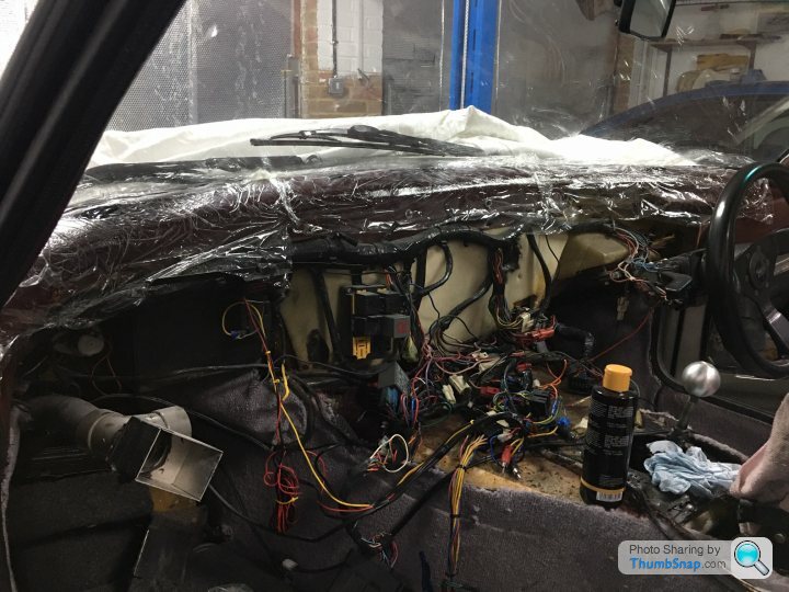
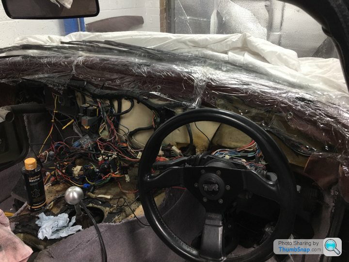
I have a Feb 1992 Griffith pre-cat and yesterday I removed the dash (not just the facia but the whole leather dash) and am now presented with a mass of wiring and to my surprise very little of the dash ventilation system present 
I really need to find a schematic (or series of photos) of the whole ventilation system to see how it should be configured, work out whats missing and then try and source replacements!
Can someone please point me in the direction of some pictures or schematic detailing the system from the blower in the front wing all the way through to the vents on top, in and under the dash?
Thanks!
Also if you're wondering why I have clingfilm on the leather at the bottom of the screen it's because it's been baked in the sun over 28 years and has separated from the fiberglass panel below and gone brittle. So I'm soaking it in Furniture Clinic leather rejuvenation over a few days which should soften it again, then clean it up and glue it back onto the fiberglass.
Any recommendations for glue to stick it back down? I'd prefer not to try and use contact adhesive as I'm going to have to squirt the glue into the small gaps between the leather and fiberglass as it hasn't separated everywhere.
Any recommendations for glue to stick it back down? I'd prefer not to try and use contact adhesive as I'm going to have to squirt the glue into the small gaps between the leather and fiberglass as it hasn't separated everywhere.
Thanks for the info Lance.
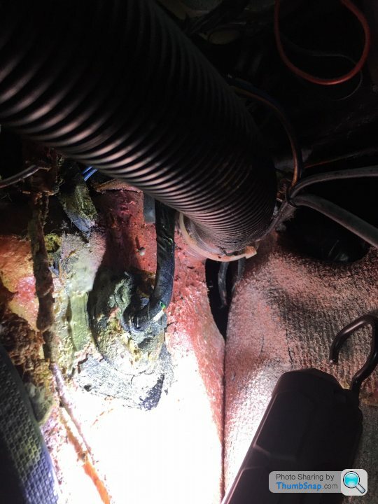
In the picture below I've drawn a circle around a black bung thats been glued into the bulkhead, which I presume is where the RHS vent got it's feed from.
I've been told by a number of people that the LHS vent on the dash is not supposed to be connected, but you're stating yours is, and in the picture below you can see a Y piece on the left most vent which looks like it goes off to the LHS dash vent, so it looks like you and I have/had all three vents working.
I need to source the missing parts as well as figuring out how it's all plumbed in to allow the flow to be directed to the windscreen, vents or foot wells, as well as making sure the hot/cold valve is work/calibrated correctly, think this could turn out to be a bigger job than anticipated!
OK I've trawled through all of these threads and looked at the various configurations of heater box and ventilation pipework and non of it matches mine
I'm starting to wonder if I have some sort of one off development configuration that then never made it onto the 500's
Here's a couple of pics
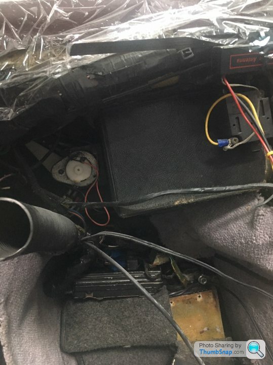
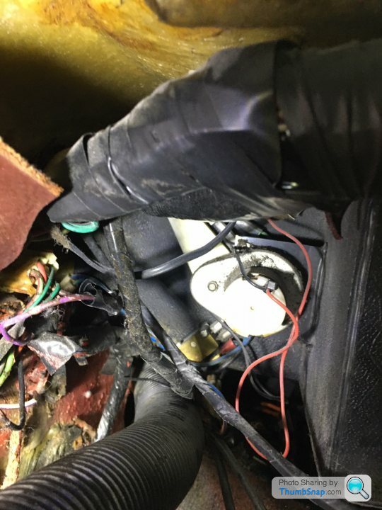
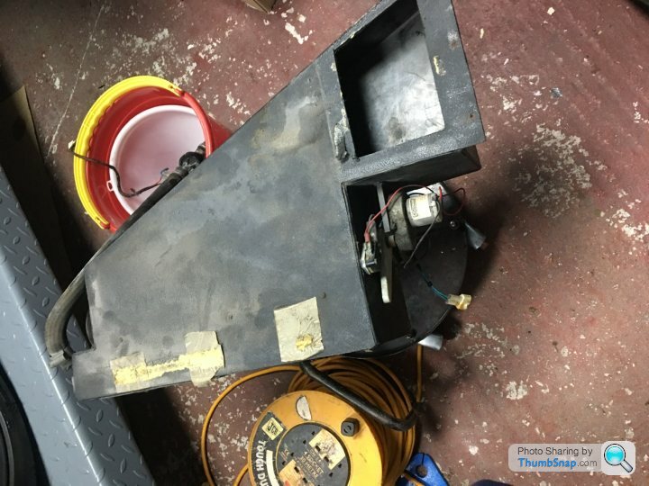
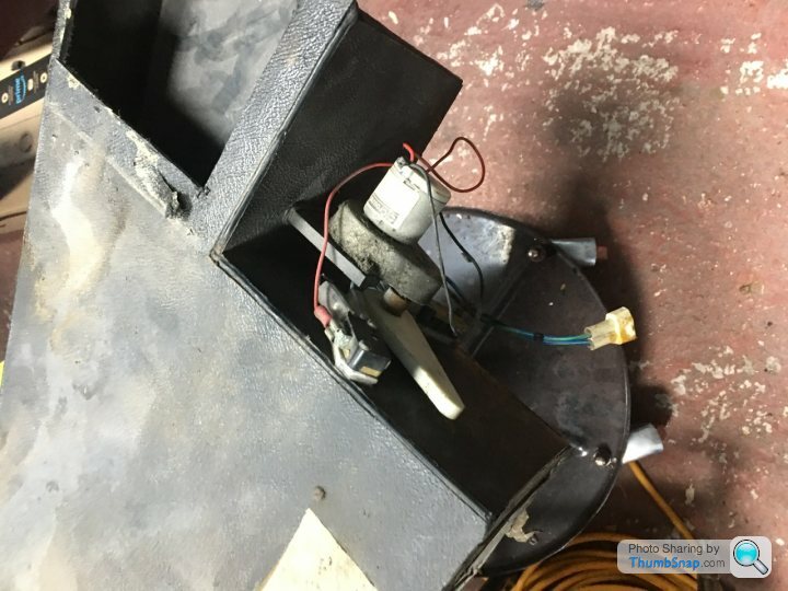
This one shows the heater box and the motor for the hot water valve I think (or is it the ventilation direction flap?). You can see the motor is at a different orientation to any of the other Griffith ventilation pictures I've seen. Also there is no output from the left hand side of the heater box (below the motor) which I've seen on all other pictures so no idea how the heat gets out to the vents?

My left hand most vent (in front of the passenger) has a tube running into the point where the inner wing meets the dashboard bulkhead too which i haven't seen before?!!? See 2nd to last pic below to see where it enters the wing
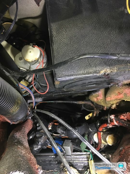
On the lower right of this picture you can see another motor.....and the left hand vent tube going into the wing rather than the heater box...On the underside of the heater box you can see a vent going down onto the passengers feet, is this a normal configuration?
Hear you can see the tube going into the passenger inner wing. I've peeled the carpet back and you can see part of a circular hole in the wing is exposed where the capets joining the wing, is this normal for a pre-cat Griff?
I'm starting to wonder if I have some sort of one off development configuration that then never made it onto the 500's
Here's a couple of pics
This one shows the heater box and the motor for the hot water valve I think (or is it the ventilation direction flap?). You can see the motor is at a different orientation to any of the other Griffith ventilation pictures I've seen. Also there is no output from the left hand side of the heater box (below the motor) which I've seen on all other pictures so no idea how the heat gets out to the vents?
My left hand most vent (in front of the passenger) has a tube running into the point where the inner wing meets the dashboard bulkhead too which i haven't seen before?!!? See 2nd to last pic below to see where it enters the wing
On the lower right of this picture you can see another motor.....and the left hand vent tube going into the wing rather than the heater box...On the underside of the heater box you can see a vent going down onto the passengers feet, is this a normal configuration?
Hear you can see the tube going into the passenger inner wing. I've peeled the carpet back and you can see part of a circular hole in the wing is exposed where the capets joining the wing, is this normal for a pre-cat Griff?
Lance this looks very like mine but you have a pre-cat so don't think yours is the same?
The pics you show, and my setup, are fed from a blower inside the wing next to the passengers left knee. I think yours has a remote blower under the nearside headlight and you also have your left vent fed from this heater box, whereas mine's coming from the wing (so will only ever be cold air).
Do you know, is Carsy's Griff a later 500?
Penelope Stopit said:
Thanks yes it confirms I have a standardish precat setup but unfortunately the link to the Maplin direct replacement micro switches is no longer valid Penelope Stopit said:
Very good then, didn't know you needed micro switches
Should you wish to search for some, if they are 3 terminal switches, search at ebay uk or in Google is SPDT Micro Switch
which is Single Pole Double Throw (SPDT)
The miniature micro switches are often found to have identical mounting point dimensions
Here's a good selection, lever length and type can be ordered to suit, these are 16 Amp which is very high for a small switch
https://www.ebay.co.uk/itm/V3-Microswitch-SPDT-16A...
Here are some more
http://www.powersperformance.co.uk/store/slug/micr...
http://www.powersperformance.co.uk/store/slug/blue...
Thanks fir the info, I order these this afternoon so hopefully they’ll suitShould you wish to search for some, if they are 3 terminal switches, search at ebay uk or in Google is SPDT Micro Switch
which is Single Pole Double Throw (SPDT)
The miniature micro switches are often found to have identical mounting point dimensions
Here's a good selection, lever length and type can be ordered to suit, these are 16 Amp which is very high for a small switch
https://www.ebay.co.uk/itm/V3-Microswitch-SPDT-16A...
Here are some more
http://www.powersperformance.co.uk/store/slug/micr...
http://www.powersperformance.co.uk/store/slug/blue...
BQLZR Micro Limit Switch V-156-1C25 Long Roll Hinge Lever Arm Momentary SPDT Snap Action LOT Pack of 5 https://www.amazon.co.uk/dp/B00RT7L6FK/ref=cm_sw_r...
I also need an identical pair without the arm but can’t find them, I’m wondering if it’s removable on these ones
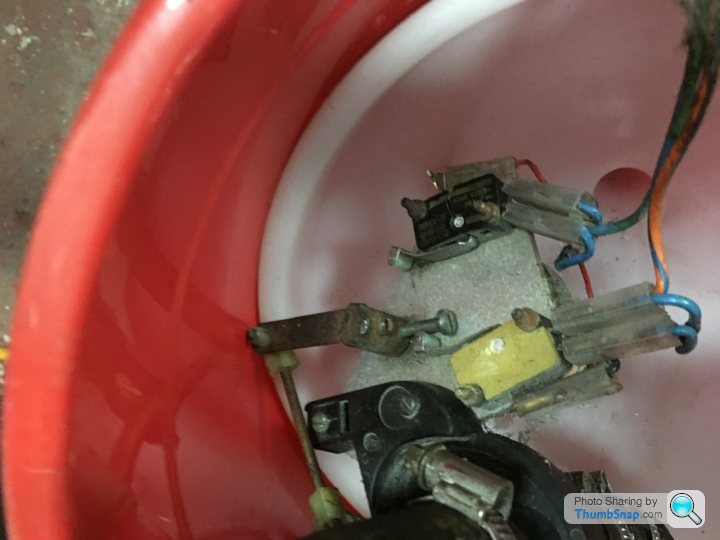
ok micro switched arrived from amazon. I’ve changed the two switches on the heater flap even though it was woking fine (and successful cut the arms off). All reassemble and working well.
Changed the broken micro switches on the heater water valve motor and reassemble and tested and it’s getting stuck half way, valve all good so pull the motor gearbox apart and find this which will explain 🤣
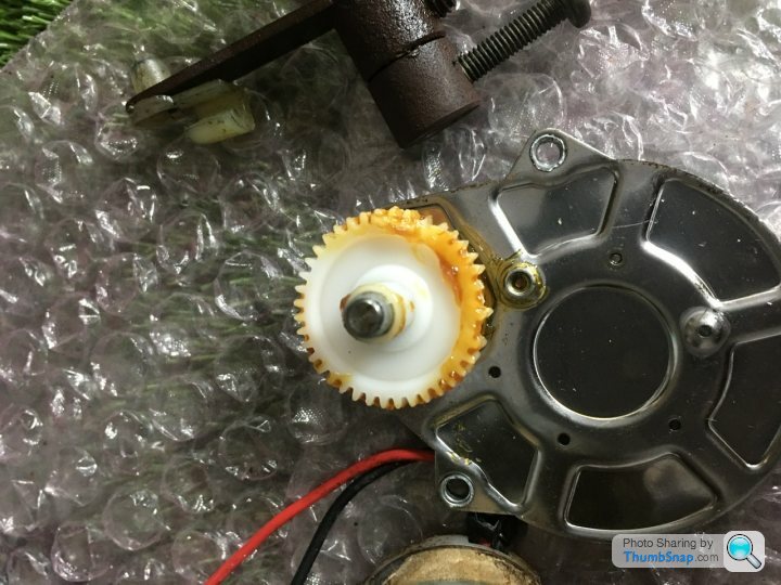

With the larger wheel only max 90deg is used so I might be able to flip it round. But the small cog in the second picture is knackered. Any ideas or do I fork out £95 for a new motor with gearbox from TVR Parts?
Changed the broken micro switches on the heater water valve motor and reassemble and tested and it’s getting stuck half way, valve all good so pull the motor gearbox apart and find this which will explain 🤣
With the larger wheel only max 90deg is used so I might be able to flip it round. But the small cog in the second picture is knackered. Any ideas or do I fork out £95 for a new motor with gearbox from TVR Parts?
OK think it's probably easier to just replace the whole motor and gearbox as one unit.
I need one of these but with the potentiometer removed as I'll continue to use the separate micro switches triggered by the control arm. However these are now no longer available so what can I use instead??
https://www.racetechdirect.co.uk/car-parts/electri...
I need one of these but with the potentiometer removed as I'll continue to use the separate micro switches triggered by the control arm. However these are now no longer available so what can I use instead??
https://www.racetechdirect.co.uk/car-parts/electri...
Managed to fix the water valve motor by salvaging the good 10 tooth drive gear and 30 tooth spindle gear from the airflow direction motor. How water valve now works perfectly and stops on the micro switches as it should!
With the airflow motor I managed to aligned the 30 tooth spindle gear so the broken teeth were on the opposite side to the 10 tooth drive gear so they never get used (as the airflow spindle only turns through 90 degrees max. For the broken 10 tooth drive gear on the airflow motor, this now works ok from micro switch to micro switch with a small hesitation at a couple of points where the missing drive gear teeth mean you have to wait until it turns through to the good teeth again. So works with a couple of hesitant points.
If the airflow gears do finally brake at least that's much easier to remove and replace that the hot water motor, so all ok for now
Gassing Station | General TVR Stuff & Gossip | Top of Page | What's New | My Stuff