Titania lambda : reason for high output?
Discussion


I've got a car in that's puzzling me somewhat.
It's on a cerbera, but seeing as the majority of knowledge is here I have put it in this section, and the lambdas are shared with other tvr models.
The issue is that the lambda sensors are outputting a range of 0 to around 1.8 volts. This is enough to send the ecu into a fault mode suspending lambdas control.
The previous garage put a new pair of lambdas in and I have done the same and it's the same story so not a lambda sensor issue (genuine NTK lambdas)
Both lambdas are affected equally so it's a global issue not just one lambda.
So far i have tried the new lambda sensors, and another ecu (easy to swap out ) .. same issue.
I have wired the lambda signals direct to the ecu .. same issue.
I have put the ecu grounds to the battery rather than the chassis earth point, and also put them to the engine block .. same problem.
Lambda heaters are getting battery voltage (around 13.6/13.7 volts engine running / alternator charging)
What could be causing the high voltage output? It's as if the lambdas are sensing a rich mixture, and then some more. But they switch back to zero with a good spiky nature like a good healthy lambda should, and the mixture is indeed being clamped to lambda=1.
It *seems* to be worse if the engine is getting up to operating temp, ie during the warm up stage where the lambdas are controlling the fuelling the peak output seems to be around 1.2 volts .. but you can watch this peak voltage get greater as the engine then heats up more. Not sure if that's significant .. other than lambda tip temp will increase with hot exhaust gases. But that still doesn't explain the behaviour.
any ideas folks?
It's the same titania sensor used in the rover V8 engines that's used in the cerbera V8 so yes the sensor is the correct one.
There's a modified version for the SP6 cerbs and early tuscans to cope with the heat of the sp6 install but Ive never had an issue using the standard NTK sensor on the V8 version.
There's a modified version for the SP6 cerbs and early tuscans to cope with the heat of the sp6 install but Ive never had an issue using the standard NTK sensor on the V8 version.
QBee said:
Given that we do sometimes have issues with new parts (I am thinking plug extenders and all manner of electrical components), have you tried a used set out of another car, ones you know work fine in that car. Or have you tried putting these new ones into a different car, for example your own Cerbera?
blaze_away said:
Just an idea, take the cerb's lambda's and stick em on a known good running Chim or Griff RV8 and see what voltages you get on there.
Sadly the only other car I have in right now is a SEAC for an emerald ecu and that is a non-runner and doesn't have any lambdas anyway. I could run the lambdas in my own cerb but .. the dead SEAC is on my only usable ramp and I'm having to do the cerbera lambdas under my rolling road ramps (they are accessed from underneath) so swapping anything into another car is a bit of a non starter sadly.LimSlip said:
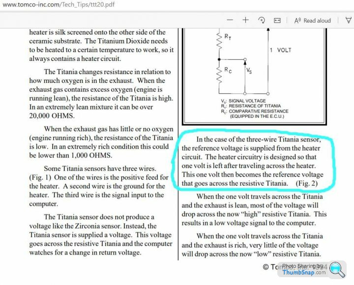
Titanium O2 sensors do not output a voltage, they change resistance according to O2 concentration. The maximum voltage across the sensor will depend on the reference current that the ECU provides.
I thought the heater circuit supplies power to the lambdas, and the conductivity of the sensor element (which varies with mixture ) then sends a small voltage out to the ecu. This is typically in the 0 - 1.2volt range but the output from 2 sets of lambdas is 0 - 1.8 volts and flagging a lambda fault in the ecu.David Beer said:
Cheap advert again joolz, surely you are the expert !
Not sure what you mean about advert, unless advertising that you are baffled by something counts as a positive. At least at the moment I don't look any worse than the previous garage, so that's something. I offer no fix no fee, so I won't be profitting from my incapability.Penelope Stopit said:
Was that voltage measured with the fault showing?
to be honest I don't know. I can't remember seeing the diagnostic screen showing anything other than normal running voltages, but I can data log the ecu later today and see if that shows up anything.blitzracing said:
I've never seen one go that high, 1.4 tops for a highly rich mixture. I've seen shorts in the loom dump 12v on the ECU input (14CUX ) and it survived with just an error code. If the device is not faulty Id be looking at a current feed on a ground plane between the sensor and ECU that would causing the sensor ground to be at a higher voltage than the ECU ground, but I suspect Im teaching you to suck eggs.
Hi Mark .. any input greatfully received right now. I'm guessing the ecu inputs on the lucas and mbe and others are well protected, they have to account for things like wires chafing through and 12v going straight into the lambda wires.cinquecento said:
Is it possible to take the belt off the altenator..or remove its 12v output. Maybe a leaking diode?
The alternator appears to be fine at the moment but I will data log the voltages at the ecu and see if anything shows up. Sadly I have no way of capturing instantaneous voltage spikes or similar voltages elsewhere as all I have is a digital voltmeter and that has a small lag / slowish sample rate.If I find anything else out today I will let you know.
Edited by spitfire4v8 on Wednesday 22 July 09:36
Edited by spitfire4v8 on Wednesday 22 July 09:54
On the subject of alternator output, the voltage after startup rose to around 14.2 volts and then settled at around 13.8/13.9 occasionally going up to 14.1 for a moment ..
I had 10mins on the phone with NTK's technical department who couldn't offer a definitive answer other than to say it's a rich mixture and to look elsewhere on the car for the issue rather than at the sensor, which is fair enough given that 4 new and 2 good used sensors have all given the same outcome so far ...
I had 10mins on the phone with NTK's technical department who couldn't offer a definitive answer other than to say it's a rich mixture and to look elsewhere on the car for the issue rather than at the sensor, which is fair enough given that 4 new and 2 good used sensors have all given the same outcome so far ...
Hi Steve .. it's not that it's a permanently rich condition per-se .. the lambdas are cycling back to zero volts and spiking back up which shows the ecu can trim the fuelling back weaker and then richer in its natural cyclical routine. What's happening is that during the natural rich reading spike the lambda output is going over the normal 1.2volts you would expect to see and heading to 1.7volts which flags an ecu fault.
I can disguise the symptom by changing the lambda sensor limits in the ecu so that the high voltage doesn't flag an error, but that's not fixing the fault, which might get worse and my short-term fudge would be useless.
I can disguise the symptom by changing the lambda sensor limits in the ecu so that the high voltage doesn't flag an error, but that's not fixing the fault, which might get worse and my short-term fudge would be useless.
GreenV8S said:
As far as I understand it, the sensor acts as half of a voltage divider, with the other half being in the ECU. So for the ECU to see too high a voltage, the supply voltage to the divider must be too high. That comes from the heater circuit. If the heater circuit ground is higher than the ECU ground, I think that could cause these symptoms. If the difference is caused by circuit or contact resistance, that could explain why the symptoms vary with heater load.
Hi Pete..About the only thing I haven't done electrically is to run a new heater ground to the same point at the ecu grounds go to. To be honest I didn't realise that a voltage offset with the heater ground could cause a fault. This is where knowing a little bit about electrics, but nothing about more electronic level lets me down. next job!
Update time .. have been for an extended run in the car today and the out of range high voltage seems to be fixed ..
It also highlights the importance of testing something even though it is difficult.
I had previously tested the lambda heater supply voltage with the fuel pump running but the engine not running. This is because the lambda plugs are on top of the gearbox on the cerb and all but impossible to access unless you are taking the lambdas out. It's certainly nigh on impossible to get any kind of testing probe down to them with the lambdas still fitted in the manifolds.
However today has been an important lesson in doing the tests properly even if they are awkward or difficult, and don't assume anything.
The voltages at the lambda heater wires with engine off were fine .. battery voltage near as dammit .. but in testing a bit further I realised the fuel pump speed began being changed when I unplug / replug the lambda connectors. On these cars the fuel pump relay also powers the lambda heater wires, so this change in pump speed I'm thinking is liklely because the wiring cannot support correctly the power for the pump and the additional power required for the lambda heaters... except the heaters tested at battery voltage previously. Further testing showed that yes when cold the lambda heaters were indeed seeing close to battery voltage, but after testing for some time on the dyno I could see the voltage gradually getting lower and lower dropping by nearly 2 volts until it was at around 12volts - it may have gone lower still but I stopped there as I had seen enough to realise there was more going on than I originally thought.
I'd not seen this effect before because previously I had foolishly stopped the heater volt test once I had seen close to battery voltage. I assumed it was ok. Had I run the engine and kept the tester on the supply wires for longer I would have seen the volt drop the other day during initial testing.
This got me checking back through the circuit and particularly that the fuel pump ran all the time once the ignition was on and immobiliser switched out .. this is not uncommon if say the ecu has picked up a fault and the quick dirty and more importantly cheap fix is to just alter the wiring to let the pump run all the time the ignition is on.
Except this wasn't just a case of someone earthing the signal wire for the pump relay coil ... Behind the fusebox and well out of sight someone had wired in an additional relay .. and badly soldered the relay power out to the fuel pump and lambda heater wires on the back of the fusebox. Why they had done this I really don't know, because with the wiring re-instated correctly at the fusebox and running through the correct fuel pump relay the voltages all returned good again, hot and cold.
See attached pic below of the wire I cut out.
Now normal power all the time is restored to the lambdas, and the fuel pump speed barely changes (nice side-effect) ..
What is puzzling though is that the high lambda signal was apparently because of a reducing heater voltage whereas I wrongly assumed that a reducing heater supply would mean a reduction in the lambda sensor output. In reality the reverse appears to be the case here. The sensor is just a resistive element which changes with mixture so this bit really baffles me still. It's almost as if the new extra supply voltage provides a damper eliminating the high signal spike. The lambda traces are still violent spikes up and down just as they should be and just as they always have been on the data logger, but the max voltage reached was too great previously, and now never goes over 1.3volts - and even under acceleration fuelling enriched mixtures never goes above 1.4v. I usually see 0-1.2 volts as the signal range so 0-1.3 I will certainly take!
In the end the rising lambda signal voltage with time wasn't anything to do with sensor tip temperatures as I had thought, but more that the supply voltage was reducing, no doubt due to the high resistance when hot of the wiring below.
Anyway .. I wish there was something waaaaay more technical as an answer to this, but this dodgy bit of wire seems to be the culprit ... fingers crossed anyway .. 3 hours of driving and not a single lambda fault flagged in the ecu .. touch wood .. etc
Steve_D said:
I feel for you. Hours of work which are very hard to justify when charging the customer.
Job well done in the end though.
Steve
I will probably end up charging out something like a quarter of the time spent .. I've learned something from it all, and the customer has already had a big bill from the previous garage .. and to be fair it's not the customer's fault I didn't find the fault sooner!Job well done in the end though.
Steve
GreenV8S said:
Excellent bit of detective work there. Would insulation piercing probes have helped you see the running voltages in this situation?
Hi Peter, the issue is access to the part of the wiring that separates out to the lambda sensors .. it's right down the back of the bulkhead on top of the gearbox so although tools of that kind would definitely have helped, its hard enough getting just your fingertips down to the wiring never mind trying to pierce the correct wire with a probe.In the end I got two lambda wiring extenders as used on the catted griffs/chims/V8S and used the (then accessible) plugs on those as my points of access.
Gassing Station | General TVR Stuff & Gossip | Top of Page | What's New | My Stuff