Paper Ship: SMS Emden (1910), 1:250
Discussion


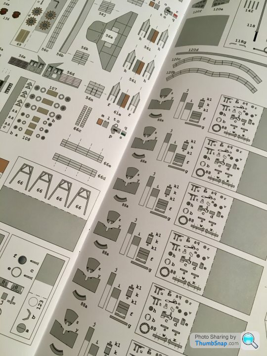
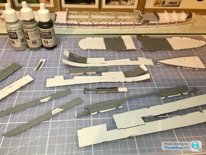
A quick trip to Hamburg this week saw me getting a new kit from the Maritime Museum. This one’s a bit bigger than my previous three, at 477 mm long. It’s also rated “Sehr Schwierig”, so in theory a bit more tricky to build too:

Also got the laser-cut set:
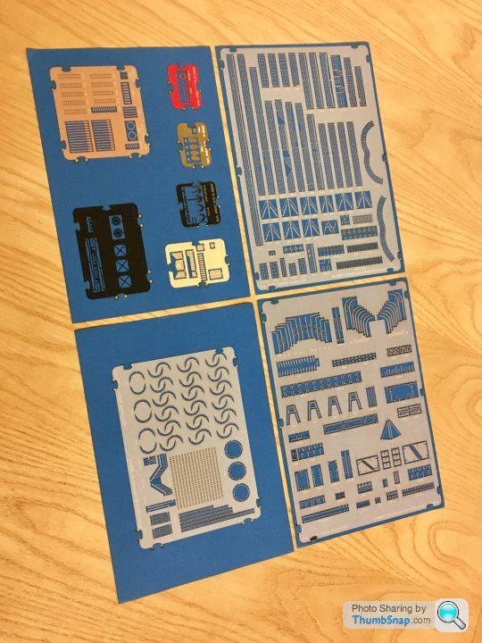
Also got the laser-cut set:
Edited by dr_gn on Thursday 12th April 10:22
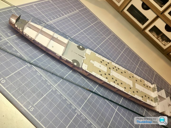
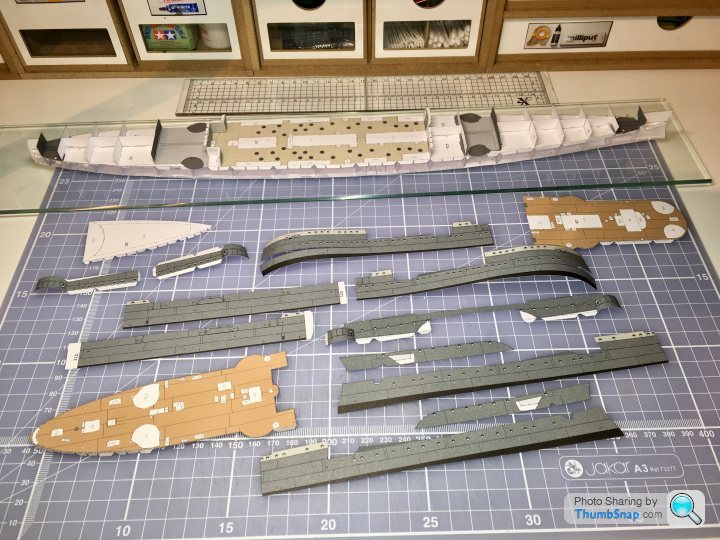
Made a start on the hull sub-structure tonight:
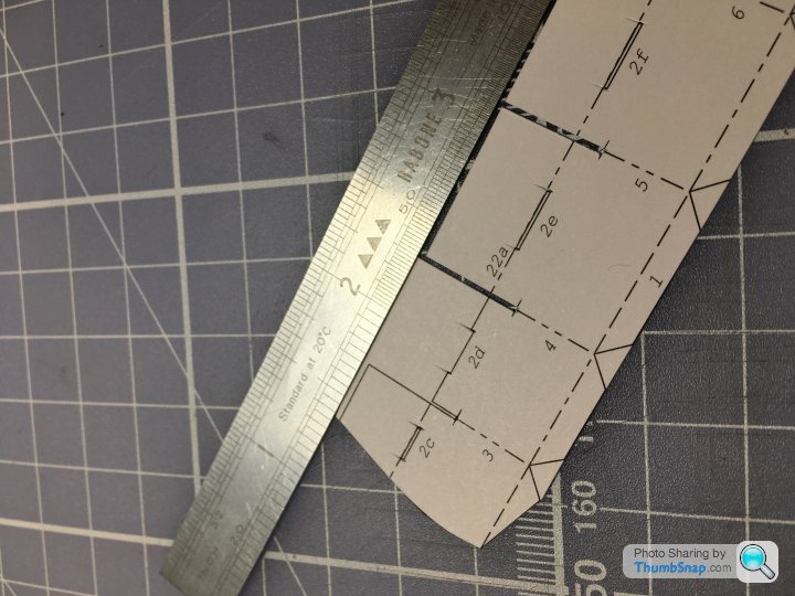
It’s made in two halves and assembled with overlapping joints:
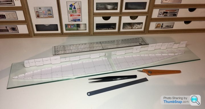
Must admit, with previous builds I’ve been super accurate with this part of the structure, and taken hours to get things perfect, only to have to cut and shut the cladding panels to fit. With this one I’ve taken a less onerous approach and stuck it all together by eye. It’s a bit of a whopper compared with the others; this is current progress with the Corvette for scale:

It’s made in two halves and assembled with overlapping joints:
Must admit, with previous builds I’ve been super accurate with this part of the structure, and taken hours to get things perfect, only to have to cut and shut the cladding panels to fit. With this one I’ve taken a less onerous approach and stuck it all together by eye. It’s a bit of a whopper compared with the others; this is current progress with the Corvette for scale:
shortar53 said:
Oh hell yeah Doc. This should be good.
I really enjoyed doing the Von Der Tann, cant wait to see how amazing your attempt at thus size turns out
I remember seeing that - looked very impressive complete. I'm hoping the hull will go together well on this one, after that, it's just cut, glue and repeat for a few months until it's done.I really enjoyed doing the Von Der Tann, cant wait to see how amazing your attempt at thus size turns out
Not looking forward to the cost of the case for this one!

robemcdonald said:
Do you start in the middle?
I would imagine that would help with the tolerance stack issue.
I didn't, but everything seems to fit where it should in terms of printed alignment, it's whether the alignment itself is right. For example, the rear deck is about 5 mm too long at the rear (according to the sub-structure), yet aligns at the front and at various points along the top edge. I'm hoping the hull sides align with the deck etc, rather than the sub-structure.I would imagine that would help with the tolerance stack issue.
There's also the issue of the hull sides spanning three levels, and the external bulkheads needing to mate to them. Any skew and it's cut-and-shut time. It might be fine.
allegerita said:
What kind of glue do you use? And even more interestestingly, how do you apply it?
I never tried any paper modelling. Well, I built a car once but that ended up in a disaster. I used hobby glue out of a tube.
I use Formula 560 canopy PVA applied with either a cocktail stick or with a small brush ( if diluted with water).I never tried any paper modelling. Well, I built a car once but that ended up in a disaster. I used hobby glue out of a tube.
One disadvantage of using pva glue is that it can warp the larger, unsupported edges. I’ve straightened some of the more critical deck and bulkhead edges with balsa strip:
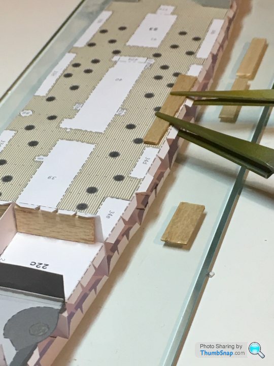
These anchor housings fit behind the hull sides. Good job I spotted them at this stage - they’re not mentioned in the instructions...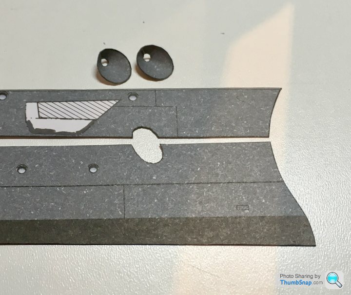
These anchor housings fit behind the hull sides. Good job I spotted them at this stage - they’re not mentioned in the instructions...
I was told to get some of this stuff for paper ship hulls (NOT detail parts):
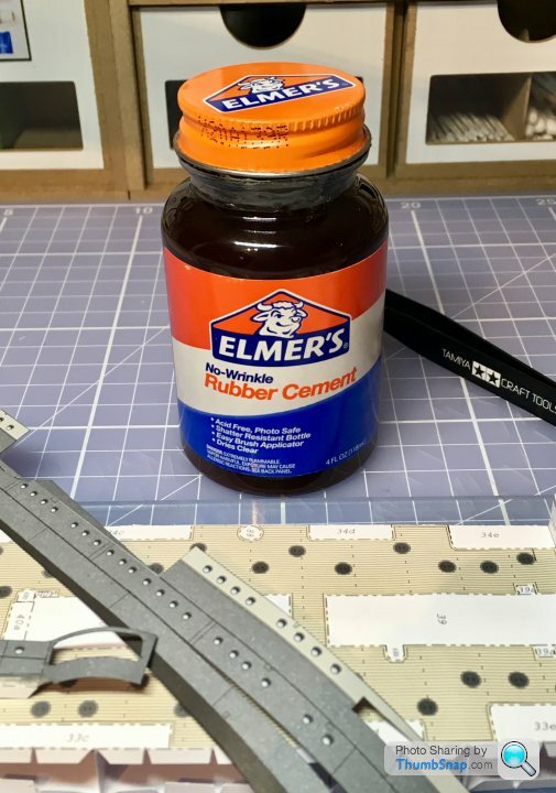
He should know his stuff - he designed the HMV Corvette.
First impressions weren’t too good - very gloopy, and fast drying similar to EvoStick contact adhesives. However, I used it on some test pieces, and it goes on ok with a cocktail stick. I’d describe it as resulting in a bond similar to a post-it note. It remains fully peelable for at least half an hour - which is perfect for positioning large parts. I think it may stay peelable, because excess can be rubbed off quite easily.
My plan is to position all the main hull sub-assemblies with Elmer’s, then wick PVA along all the external joints to make a final, stronger bond.
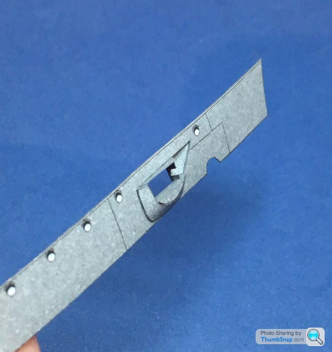
The bow casemate guns aren’t very clearly explained in the instructions. Some views show them closed up, with just the barrel showing:
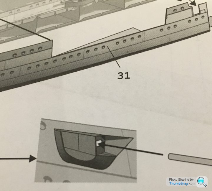
The alternative option is open, but apparently without the blister or covers:
Only later is the open option revised to this:
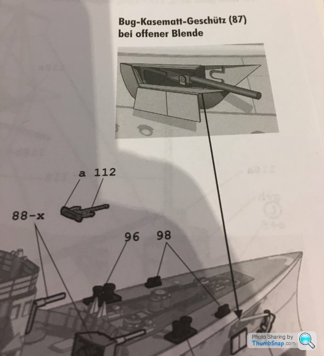
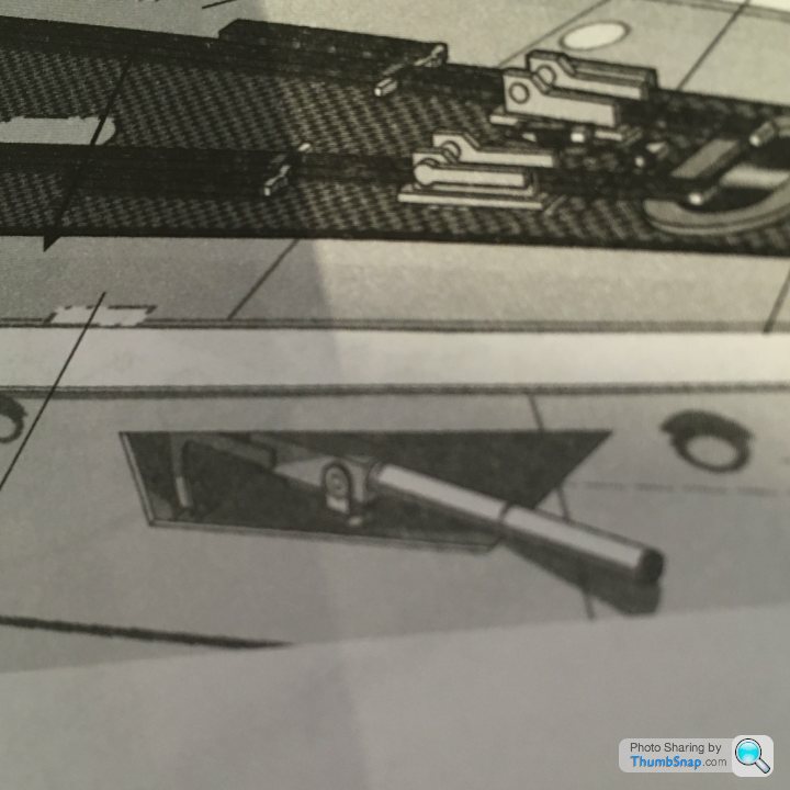
I had a guess at this being right (although the slotted panel might have been intended to be flat to the hull:
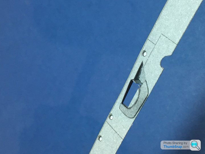
I doubt the inside will be visible, but I painted it anyway:
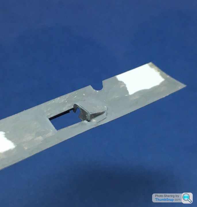
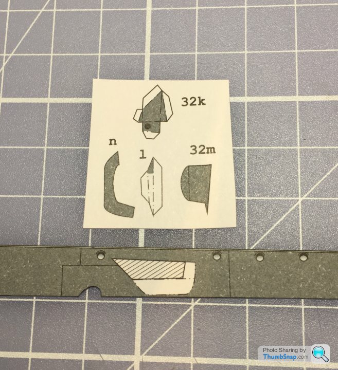
Part 31/32m needs to be split into 4 parts for the open option, yet most of the cut lines are missing. I made a best guess, so hopefully it will be ok.
I’ll add the open doors later.
The alternative option is open, but apparently without the blister or covers:
Only later is the open option revised to this:
I had a guess at this being right (although the slotted panel might have been intended to be flat to the hull:
I doubt the inside will be visible, but I painted it anyway:
Part 31/32m needs to be split into 4 parts for the open option, yet most of the cut lines are missing. I made a best guess, so hopefully it will be ok.
I’ll add the open doors later.
The masts on this one are huge, and there’s plenty of rigging between and around them. I’ve modified the model slightly by bonding these aluminium tubes into the hull:
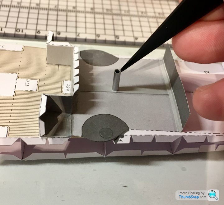
They’ll form a much stronger location for the masts than the paper deck. I’ll bond a wire spigot into the bottom half of each tubular paper mast, and Araldite it into the aluminium sockets near the end of the build. None of the aluminium or wire will be visible once complete.
They’ll form a much stronger location for the masts than the paper deck. I’ll bond a wire spigot into the bottom half of each tubular paper mast, and Araldite it into the aluminium sockets near the end of the build. None of the aluminium or wire will be visible once complete.
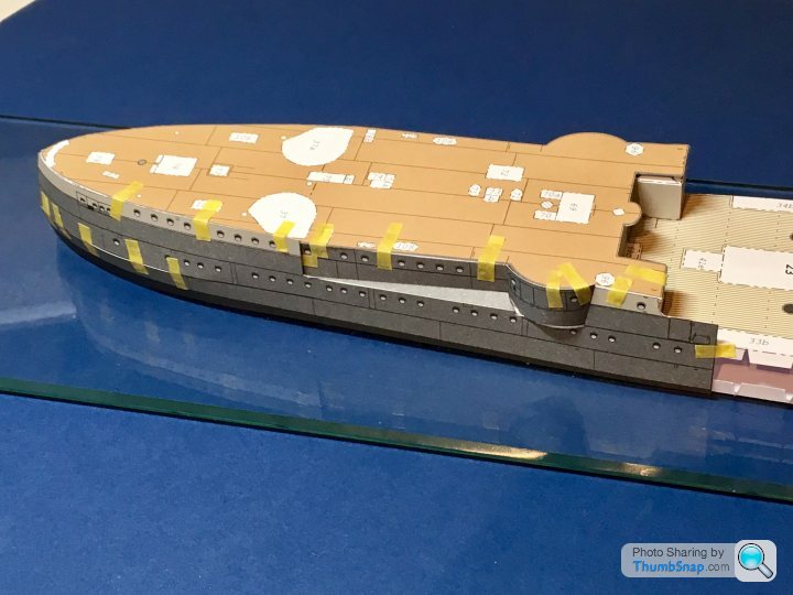
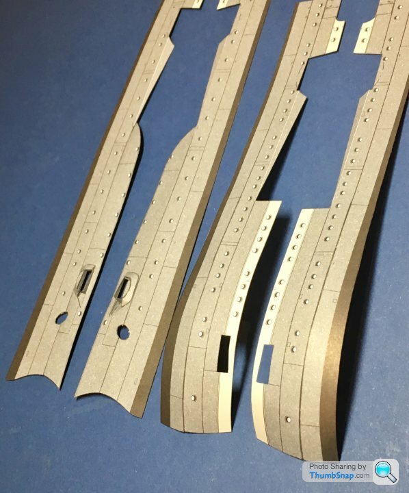
Now things get tricky. There are 4 stern panels and the deck, all of which need assembling to pretty close tolerances if there are to be no gaps. The areas around the casemate guns comprise curves and angled sections, all of which need to mate pretty much perfectly. The stern sides also have cuts in them which when closed, form an angled, curved profile. Starting with these, after painting all exposed edges, I tacked them in place with Tamiya tape:
Then painted pva along the joints, backed up with thin tracing paper to form a shear joint rather than an edge joint:
Then painted the back to make any small gaps opaque. The upper and lower bow sides were joined in the same manner:
This results in - pretty much - perfect joins, with no excess glue on the outside:
On to the casemate panels:
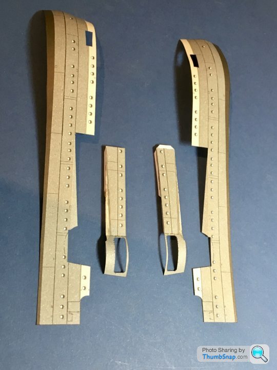
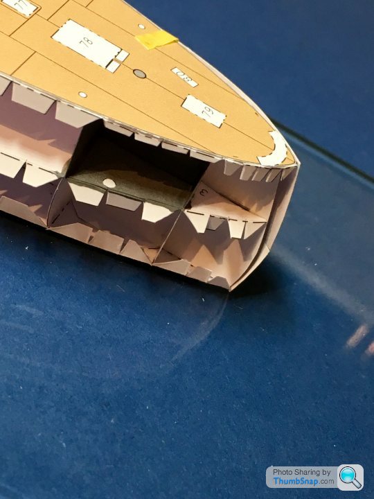
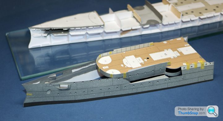
The ends were trimmed to the right length, and joined to the stern sides as above. Then, the two sub-assemblies were fitted to the rear deck using Elmer’s glue, which allowed adjustment to suit the casemate bulges. PVA was then brushed along the inside edges of the hull-deck interface. This formed a shell structure:
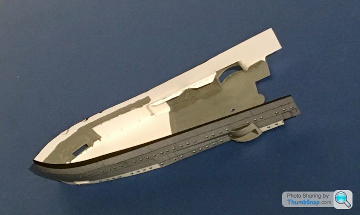
I opted for this shell method because it simplifies the critical, and very difficult, hull-deck joint, allowing access to the inside and outside for adjustments and application of glue.
The insides will be finally painted dark grey in case anything is visible from the gun ports (unlikely, but possible). The shell fitted nicely to the stern sub-structure, at least as a test-fit. The aluminium rod represents the mast spigot, which lines up nicely with its previously fitted socket.
Next, the bow shell structure.
Then painted pva along the joints, backed up with thin tracing paper to form a shear joint rather than an edge joint:
Then painted the back to make any small gaps opaque. The upper and lower bow sides were joined in the same manner:
This results in - pretty much - perfect joins, with no excess glue on the outside:
On to the casemate panels:
The ends were trimmed to the right length, and joined to the stern sides as above. Then, the two sub-assemblies were fitted to the rear deck using Elmer’s glue, which allowed adjustment to suit the casemate bulges. PVA was then brushed along the inside edges of the hull-deck interface. This formed a shell structure:
I opted for this shell method because it simplifies the critical, and very difficult, hull-deck joint, allowing access to the inside and outside for adjustments and application of glue.
The insides will be finally painted dark grey in case anything is visible from the gun ports (unlikely, but possible). The shell fitted nicely to the stern sub-structure, at least as a test-fit. The aluminium rod represents the mast spigot, which lines up nicely with its previously fitted socket.
Next, the bow shell structure.
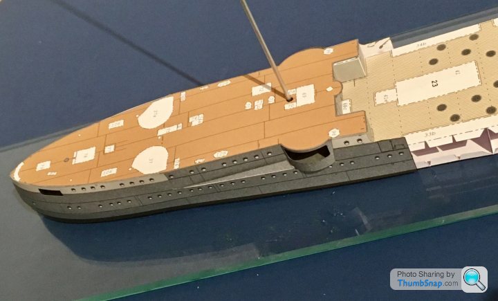
On to the bow section, and it's even more complex than the stern, being linked side-to side with a curved upper deck bulkhead:
I'm in the process of temporarily taping, then tacking various key points with PVA. Once complete, It'll hopefully slip over the substructre in the same way as the stern, leaving just the flat sides to add.
I'm in the process of temporarily taping, then tacking various key points with PVA. Once complete, It'll hopefully slip over the substructre in the same way as the stern, leaving just the flat sides to add.
Gassing Station | Scale Models | Top of Page | What's New | My Stuff