Stuart Twin Victoria (Princess Royal) Mill Engine
Discussion


This will be my second model engineering project after the 10V:
https://www.pistonheads.com/gassing/topic.asp?h=0&...
It's a model of a twin cylinder mill engine, based on the Stuart Models Twin Victoria:
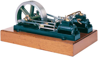
Back in the mid '80's, "Tubal Cain" (Tom Walshaw) who was a prolific contributor to Model Engineer magazine, published a series of articles on how he modified and detailed the Stuart Twin Victoria. He called this refined version the "Princess Royal".
Refinements included a more realistic cylinder mounting method, re-designed connecting rods, incorporating scale bearings and caps, a working governor, a more refined ropewheel (flywheel), more relistic oilers and scale handrails.
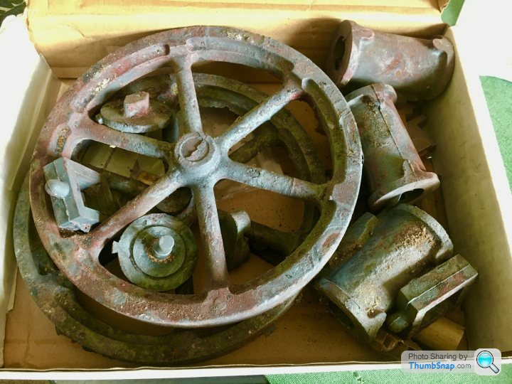
The Stuart Models kit is very expensive, so after getting advice from the ME forum, I've opted to buy only the castings. I will fabricate the beds from aluminium, and make the rest from stock materials, which I've already got from a local supplier:
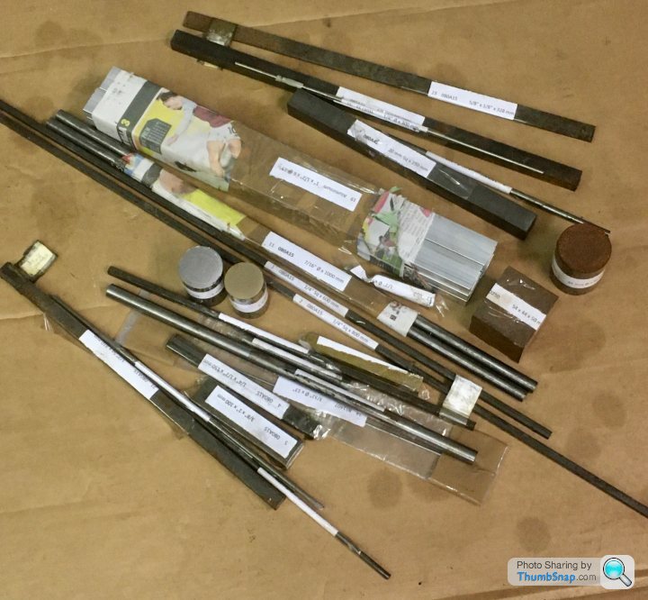
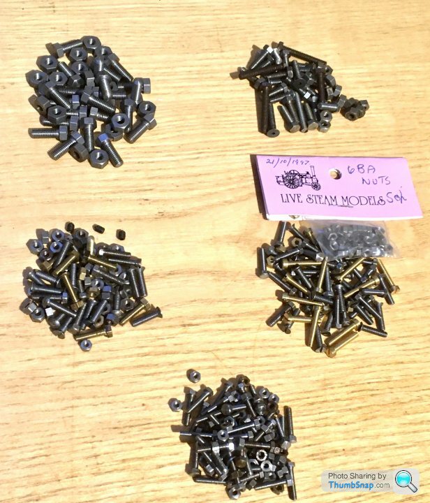
The BA fasteners I'll get from a specialist. I did buy the Twin Victoria plans, but most if not all the drawings for the Princess Royal version are in the ME Magazine articles:
The total saving doing it this way is around £250. It'll be a huge challenge - especially the governor, but that's what makes it fun.
Currently fettling the lathe and mill, so this one will probably get started properly after Christmas.
https://www.pistonheads.com/gassing/topic.asp?h=0&...
It's a model of a twin cylinder mill engine, based on the Stuart Models Twin Victoria:
Back in the mid '80's, "Tubal Cain" (Tom Walshaw) who was a prolific contributor to Model Engineer magazine, published a series of articles on how he modified and detailed the Stuart Twin Victoria. He called this refined version the "Princess Royal".
Refinements included a more realistic cylinder mounting method, re-designed connecting rods, incorporating scale bearings and caps, a working governor, a more refined ropewheel (flywheel), more relistic oilers and scale handrails.
The Stuart Models kit is very expensive, so after getting advice from the ME forum, I've opted to buy only the castings. I will fabricate the beds from aluminium, and make the rest from stock materials, which I've already got from a local supplier:
The BA fasteners I'll get from a specialist. I did buy the Twin Victoria plans, but most if not all the drawings for the Princess Royal version are in the ME Magazine articles:
The total saving doing it this way is around £250. It'll be a huge challenge - especially the governor, but that's what makes it fun.
Currently fettling the lathe and mill, so this one will probably get started properly after Christmas.
laters said:
Another one to look forward too as I really enjoyed watching the progress of your 10V.
Brought back a lot of memories of the principles we were taught in the engineering department at collage all those years ago.
Would love a lathe and mill but just don't have the space.
Cant wait too see this one progress as your 10V is another level, as are all your other models too.
Thanks Laters - glad you enjoyed following it.Brought back a lot of memories of the principles we were taught in the engineering department at collage all those years ago.
Would love a lathe and mill but just don't have the space.
Cant wait too see this one progress as your 10V is another level, as are all your other models too.
fourfoldroot said:
dr_gn said:
I did think you weren’t saving much on the full kit, but realised Stuart prices are cunningly all ex vat.Massive saving on the fully machined kit at £2.2 k.! And you get the joy of removing the excess material to reveal the perfectly machined castings underneath.
Castings & Extrusions (including VAT and postage) = £310.66
Raw materials (including VAT and collection) = £75.16
ME & BA Fasteners (including VAT and postage) = £42.80
Stuart Plans (which I didn't really need in the end!) = £16.68
Total "DIY Kit" = £445.30
Stuart Models Twin Victoria un-machined kit (including VAT and postage) = £664.74
So my total saving by doing it this way is £219.44 - or looking at it another way, a complete Stuart 10V kit including delivery and VAT, plus £100 left over.
It's also worth remembering that due to the supplied lengths of materials and minimum fastener quantities, I've actually ended up with a significant amount of spare materials over what I'd get in the Stuart kit.
After all that, if I was at a show, and saw someone asking £445 for the pile of bits that I've currently got in a box, I'd laugh at them.
ETA you're a bit off with the cost of a machined kit - it would be £2,512.92 inc. VAT and delivered.
If you want it "ready to run" it'll set you back an eye watering £3,844.50 inc. VAT and delivered.
Edited by dr_gn on Saturday 12th December 13:28
fourfoldroot said:
Incredible, over £1k to assemble. Maybe a days work even with a bit of fettling. I’m in the wrong job!
I have just been given more BA nuts and bolts than i can use in a lifetime so if there is anything you need just pm me. Mainly in the 4-8 BA range which is the ones you need.
They certainly don’t seem shy when it comes to prices...You could literally buy the full kit, a lathe, a milling machine and pretty much all the tooling required for the assembled price. I have just been given more BA nuts and bolts than i can use in a lifetime so if there is anything you need just pm me. Mainly in the 4-8 BA range which is the ones you need.
Appreciate the offer of the nuts and bolts. I can send a list if you could see what you have? Happy to pay you for them rather than a random supplier. Thanks!
Turn7 said:
Ah good, I really enjoyed the last build, even though a lot of it is way above me, having never used a lathe....
Glad you liked it. I’d only used a lathe for very basic work before the 10V, and never really used a mill. It’s surprising how quickly you pick up the basics, and after that you can figure most things out one way or another. The advice from here and particularly the ME forum was invaluable. I suppose pre-internet Id have been stuck with learning from books or having the faff of joining a model engineering club and having to actually talk to people 
Been working a bit more on the soleplate CAD (I'm fabricating them out of aluminium to save another £120 on castings). Also spent some time verifying the geometry of the piston stroke/crosshead location/connecting rod etc:
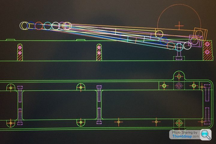
Crank centreline works out spot on the same height as the cylinder axis, and the mid-stroke crosshead position is exactly half way between the guide rail hole centres, so my imperial/metric conversion must have been correct.
Looks like there's a clash with the big end bearing cap if using the original casting dimensions though, so I'll have to extend the sides a bit:
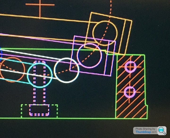
Better to find out now than when assembling it...I do seem to remember someone somewhere mentioning this issue with the connecting rod, and the casting needing a slot filing in it. I thought they meant the rod itself clashed with a soleplate cross brace. I've seen a video online where it looks perilously close, which is why I shortened them, but they must have meant the bearing cap.
Crank centreline works out spot on the same height as the cylinder axis, and the mid-stroke crosshead position is exactly half way between the guide rail hole centres, so my imperial/metric conversion must have been correct.
Looks like there's a clash with the big end bearing cap if using the original casting dimensions though, so I'll have to extend the sides a bit:
Better to find out now than when assembling it...I do seem to remember someone somewhere mentioning this issue with the connecting rod, and the casting needing a slot filing in it. I thought they meant the rod itself clashed with a soleplate cross brace. I've seen a video online where it looks perilously close, which is why I shortened them, but they must have meant the bearing cap.
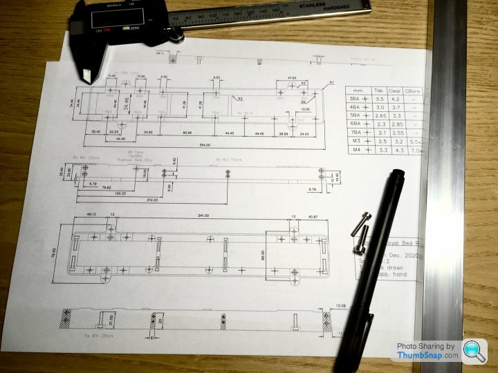
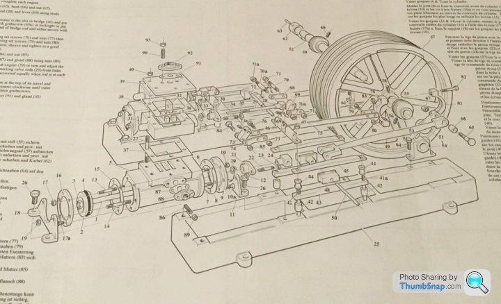
Still too cold to do anything significant in the garage, so I thought I'd at least make some jigs to help get the tapers on the simulated bed castings right. The beds are the long things at the the bottom of the diagram here:
First thing to do will be to mill the side bars to the correct overall length, then co-ordinate drill and counterbore all eight holes per bar. Each long side has two M4 screws to secure each end, and two pairs of M3 screws in the middle (slightly staggered), for the stiffeners.
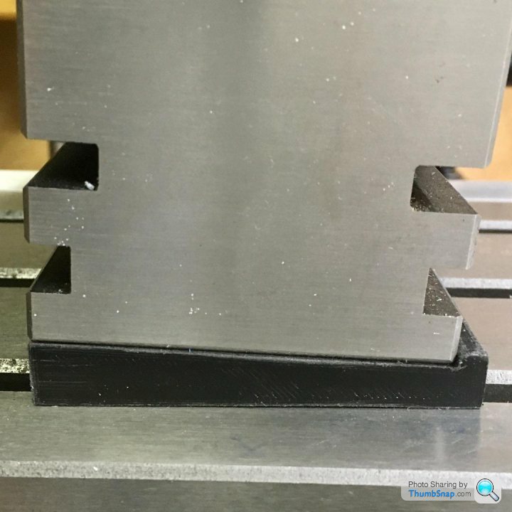
Next job, while the bars still have parallel sides, will be to mill the draw angle on the ends. I 3D printed a wedge to fit under the vice to help get this right:
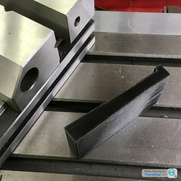
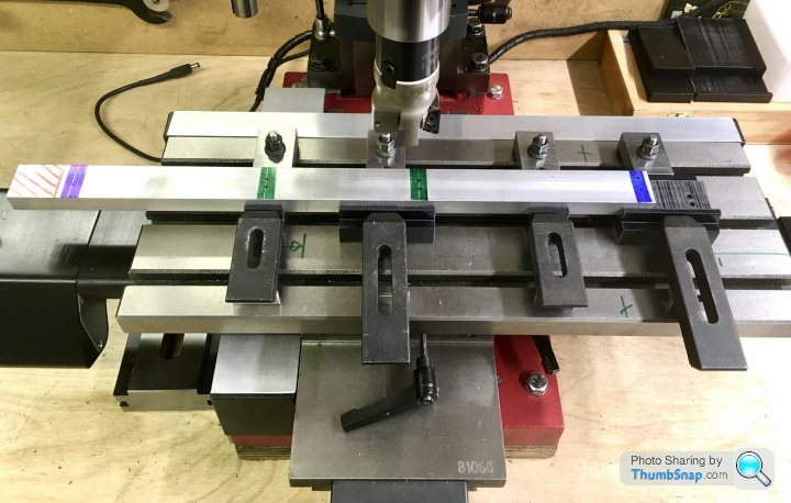
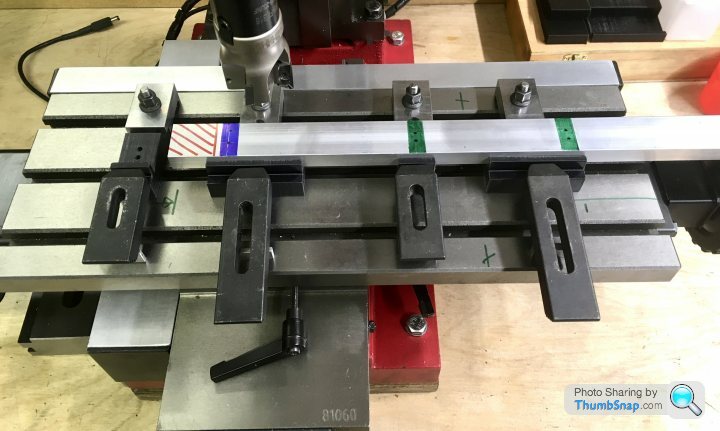
The mill bed isn't long enough to machine the draw angle along the outer faces of the aluminium bar in one go, so I'll have to do it in two stages. I've made some more jigs to help with this. The jigs are flat on the bottom, and have the draw angle on their upper seating faces:
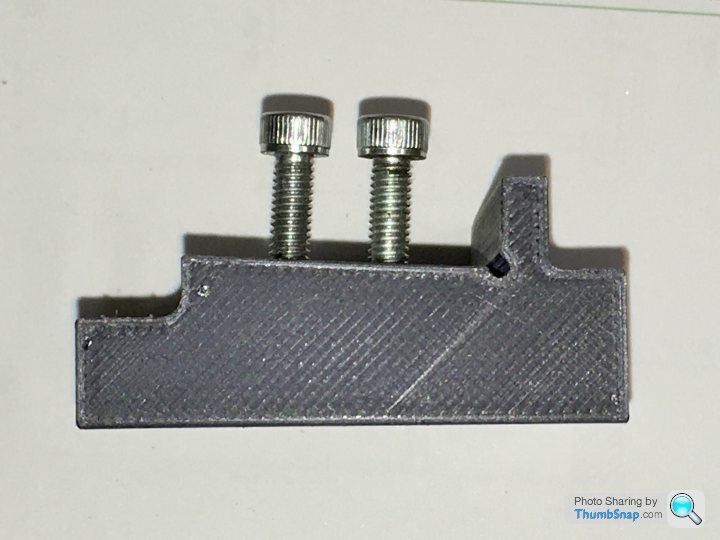
I printed in some hexagonal pockets which securely grip nuts of the appropriate size. I can then just screw the bar to the jigs, and the heads will be below the cut face. There are four blocks, two with pairs of small holes, and two with large and small hole pairs, spaced such that they can be orientated on the bed accommodate both bar positions:
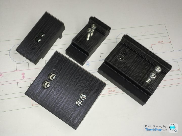
I can hopefully move the bars to both positions without having to adjust anything, just by using different hole pairs:
It's complicated by the middle hole pairs not being central between the end holes, so it's very easy to get confused and not end up with the correct handed parts with the counterbores and draw angle on the right faces. I will have to triple check and write down a machining sequence, but so far I think I'll need two configurations of jig to do everything correctly - basically turn the jigs as a set through 180 degrees on the bed. However, I wouldn't be surprised if another length of bar will need to get procured at some point:
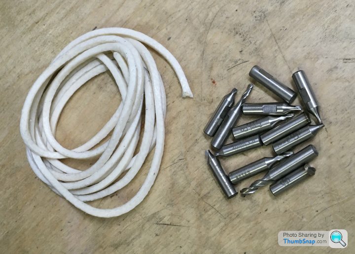
I also obtained some PTFE impregnated cord for the piston rings, and some scrap disposable tooling to grind to shape for the between centred boring bar I'll be making for the cylinders:
First thing to do will be to mill the side bars to the correct overall length, then co-ordinate drill and counterbore all eight holes per bar. Each long side has two M4 screws to secure each end, and two pairs of M3 screws in the middle (slightly staggered), for the stiffeners.
Next job, while the bars still have parallel sides, will be to mill the draw angle on the ends. I 3D printed a wedge to fit under the vice to help get this right:
The mill bed isn't long enough to machine the draw angle along the outer faces of the aluminium bar in one go, so I'll have to do it in two stages. I've made some more jigs to help with this. The jigs are flat on the bottom, and have the draw angle on their upper seating faces:
I printed in some hexagonal pockets which securely grip nuts of the appropriate size. I can then just screw the bar to the jigs, and the heads will be below the cut face. There are four blocks, two with pairs of small holes, and two with large and small hole pairs, spaced such that they can be orientated on the bed accommodate both bar positions:
I can hopefully move the bars to both positions without having to adjust anything, just by using different hole pairs:
It's complicated by the middle hole pairs not being central between the end holes, so it's very easy to get confused and not end up with the correct handed parts with the counterbores and draw angle on the right faces. I will have to triple check and write down a machining sequence, but so far I think I'll need two configurations of jig to do everything correctly - basically turn the jigs as a set through 180 degrees on the bed. However, I wouldn't be surprised if another length of bar will need to get procured at some point:
I also obtained some PTFE impregnated cord for the piston rings, and some scrap disposable tooling to grind to shape for the between centred boring bar I'll be making for the cylinders:
Edited by dr_gn on Sunday 31st January 15:12
Simpo Two said:
That is serious modelmaking!
I'll stick to wood, it's easier to cut and you don't have to heat it to 3,000C...
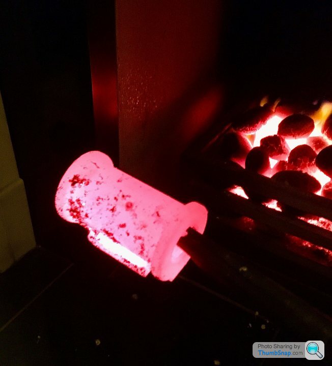
To be fair it was only a question of chucking in the fire for the evening and hoping for the best. It's supposed to make it cut like butter.I'll stick to wood, it's easier to cut and you don't have to heat it to 3,000C...
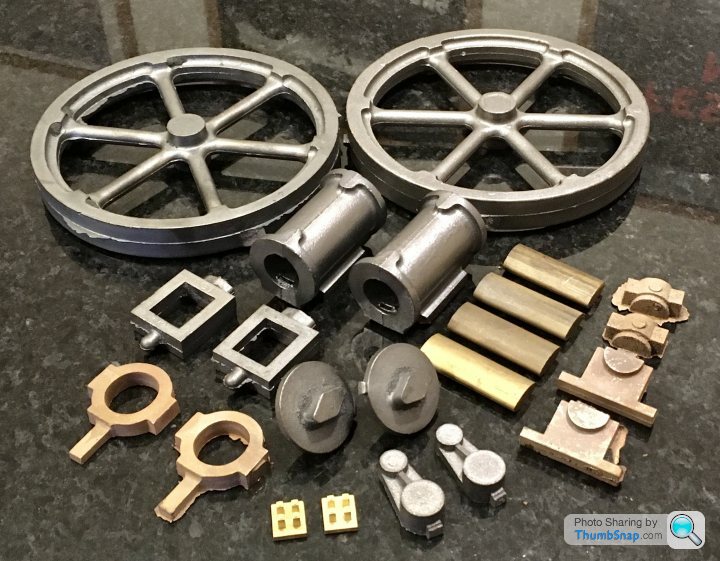
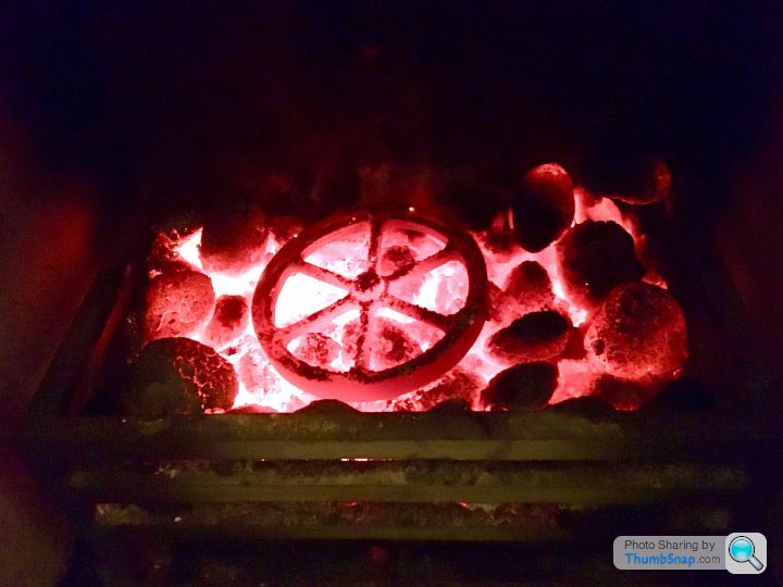
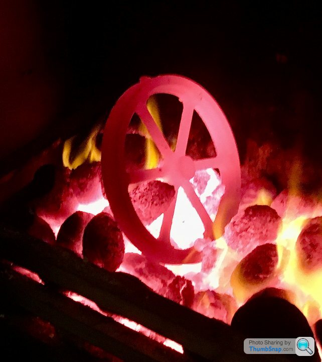
After the test on Friday worked, I put the whole lot in the fire last night, and got a nice even spread of fuel:

This is how they came out this morning:
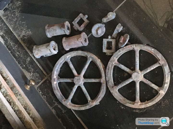
One of the cylinder caps had stuck itself to a spoke, but it pinged off after I hit it with the poker. All seems a bit medieval, but it's all good fun.
There's a hell of a long way to go with this one - especially at this rate...
fourfoldroot said:
No more hard spots. Now you have to leave them outside for a couple of years to de-stress, with regular “watering “. A company on the Sheepbridge Estate , Chesterfield, used to have acres of stacked cylinder liners outside, all going rusty. I think the theory was the temperature swings helped relieve the internal stresses.
I seem to remember all the ‘80’s BMW four cylinder Turbo F1 engine blocks were from old road cars that had had all their internal stresses aged out of them.fourfoldroot said:
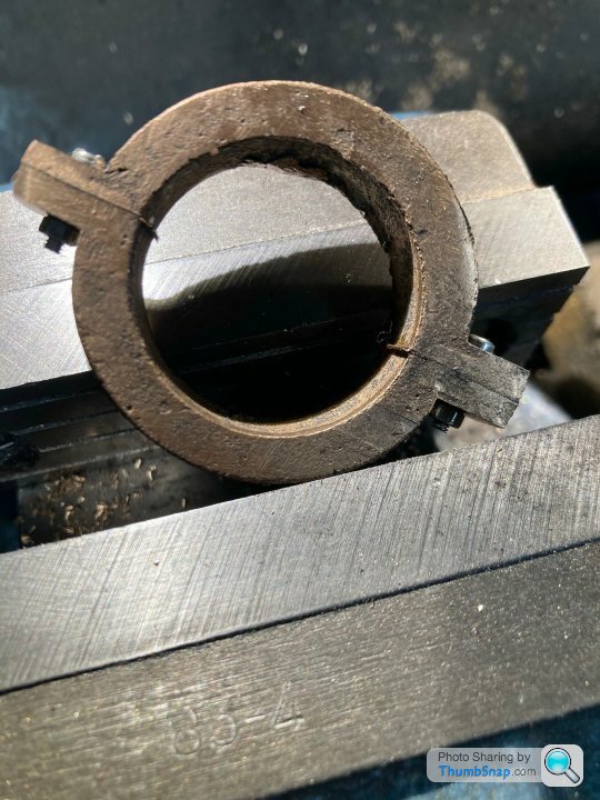
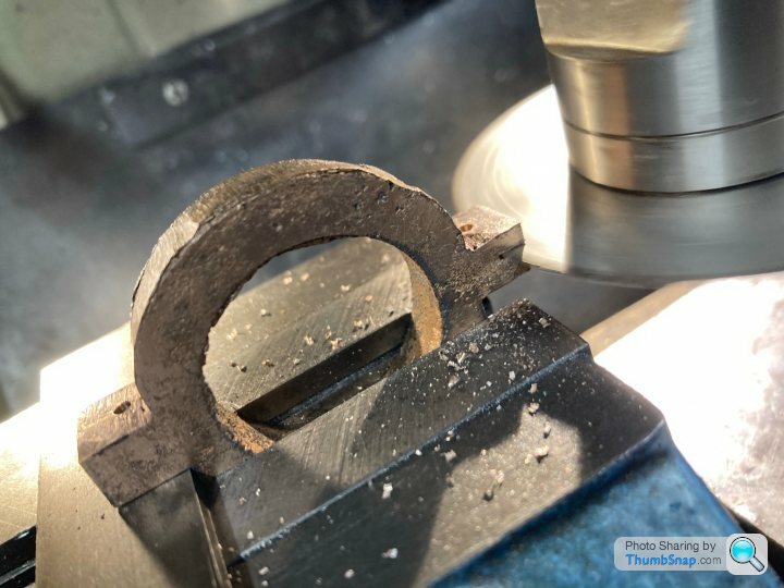
I’ve just machined this eccentric strap from a gunmetal casting. I was shocked how much it sprang apart from the released stresses when I released the bolts holding the two parts. I had to remount it and true up the bore which was a pain because it was quite spindly by then.
 [url]
[url]
 |https://thumbsnap.com/wHeBg8Ba[/url]

I suppose it's one of the multitude of subtleties of Model Engineering (or real engineering for that matter). You have to deal with things that you wouldn't necessarily expect to have to deal with. Decent machine tools are great, but a lot of work is dealing with things like spring cuts (ie not expecting a dial or DRO setting to correspond to a finished piece!), potential hard spots or internal stresses springing things apart. It's amazing that anything fits together at all. [url]|https://thumbsnap.com/wHeBg8Ba[/url]My workplace was initially set up for research purely into optimising machining of thin walled aerospace components and tuning out the vibrations of the parts and tools to give the fastest possible material removal rates. All sorts of clever stuff involved in terms of listening for resonances and engineering them out using dampers. So there are plenty of people to ask about machining, but the more you ask, the less you know.
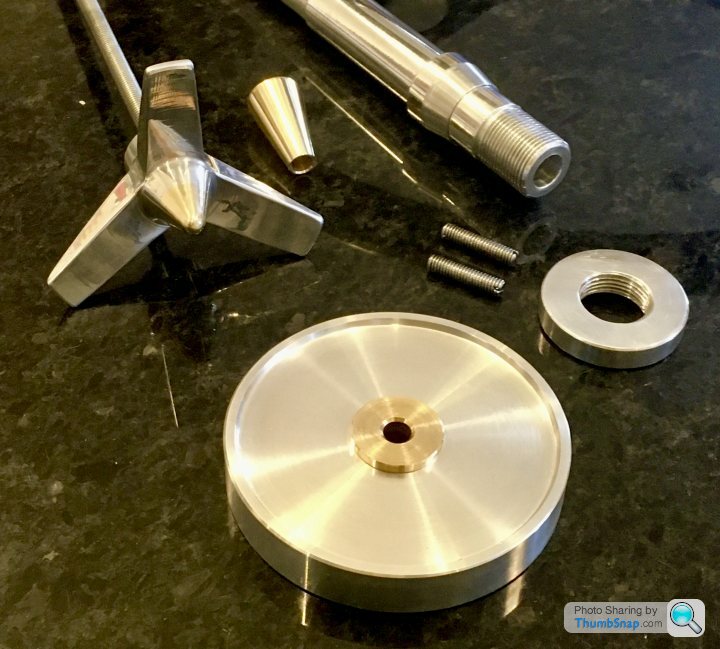
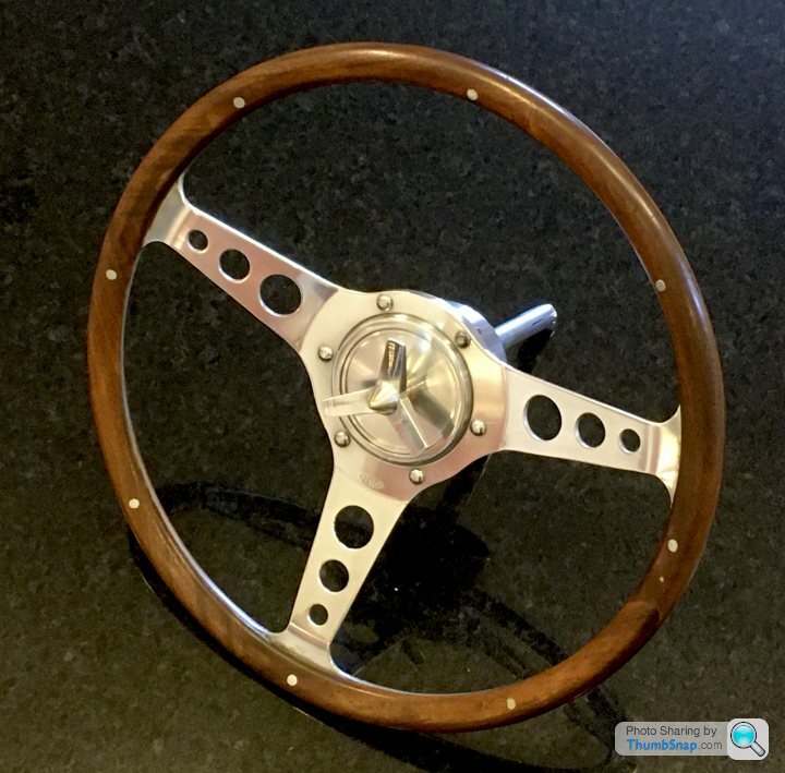
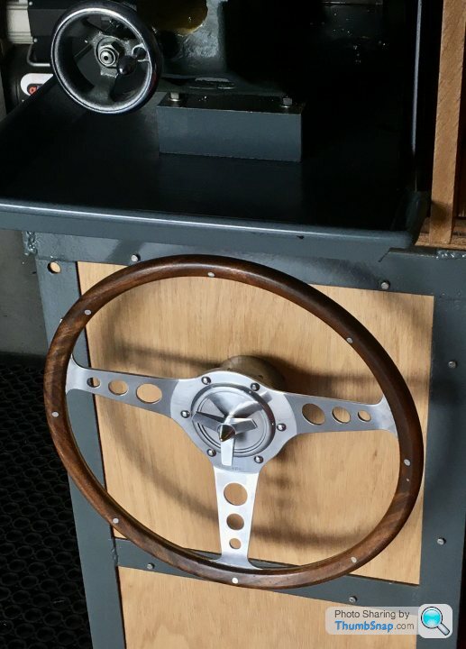
As a prelude to starting this next steam engine, I've been fettling the lathe and mill, and getting a few bits sorted that I thought would be useful for the next build. The first thing was to make a hand crank for the chuck to make threading easier. I was going to buy one, then noticed the old steering wheel hanging on the wall that my dad fitted to the MGB. When it was rebuilt, we re-fitted the original, so this one was spare. I had a brainwave and through it might even be better to have a wheel for threading rather than a crank:
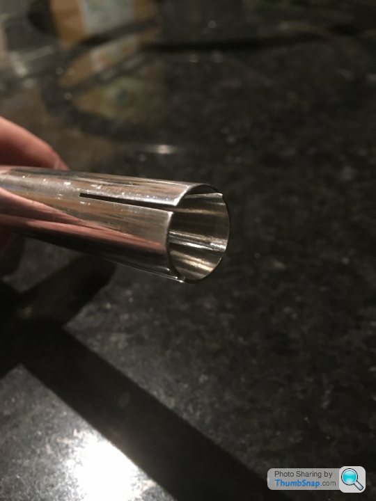
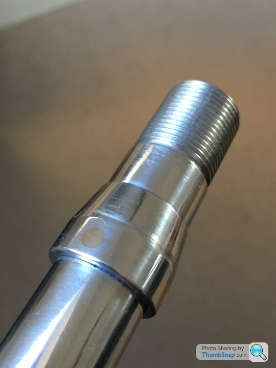
I made a split spindle to fit in the lathe shaft, and a brass cone to fit in the end to expand it and lock it in place:
The steering wheel has a location taper, which I tried to replicate. I made the taper separately, and Loctited and through-pinned it to the shaft with brass pins, before machining flush:
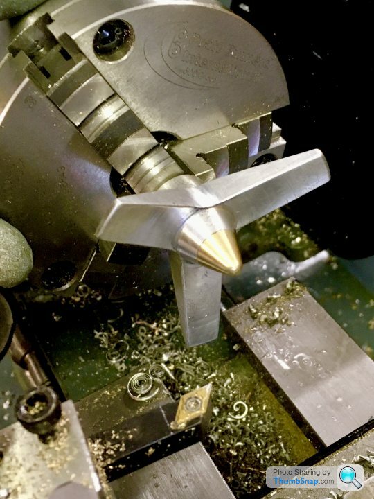
Then I needed a locking wheel to pull the cone into the shaft. I thought I go for a wheel spinner/propeller type thing to make it look a bit interesting, and be nice to use. I made one by a combination of milling and turning:
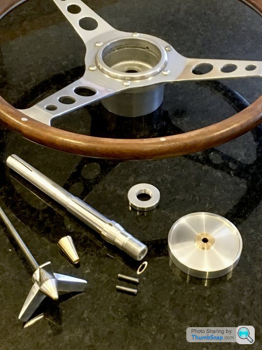
Here are the component parts I made, along with the wheel:
And here it is all assembled:
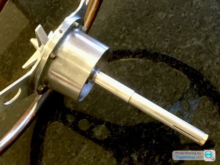

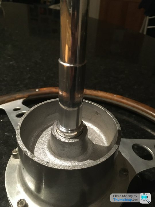
Fits very easily into the spindle, and it only takes 1/4 turn to lock it solid:

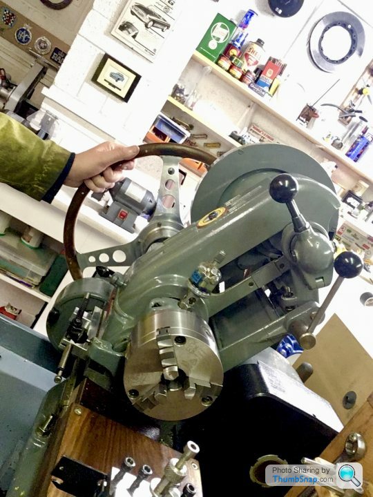
I can easily turn it while messing about at the far end of the tailstock - it works really nicely:
Also found a place to store it - in a block screwed to the inside of my lathe stand:
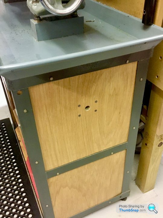
The wheel itself is un-modified, so if I decide to re-fit it to the car, no problem.
Cheers!
I made a split spindle to fit in the lathe shaft, and a brass cone to fit in the end to expand it and lock it in place:
The steering wheel has a location taper, which I tried to replicate. I made the taper separately, and Loctited and through-pinned it to the shaft with brass pins, before machining flush:
Then I needed a locking wheel to pull the cone into the shaft. I thought I go for a wheel spinner/propeller type thing to make it look a bit interesting, and be nice to use. I made one by a combination of milling and turning:
Here are the component parts I made, along with the wheel:
And here it is all assembled:
Fits very easily into the spindle, and it only takes 1/4 turn to lock it solid:
I can easily turn it while messing about at the far end of the tailstock - it works really nicely:
Also found a place to store it - in a block screwed to the inside of my lathe stand:
The wheel itself is un-modified, so if I decide to re-fit it to the car, no problem.
Cheers!
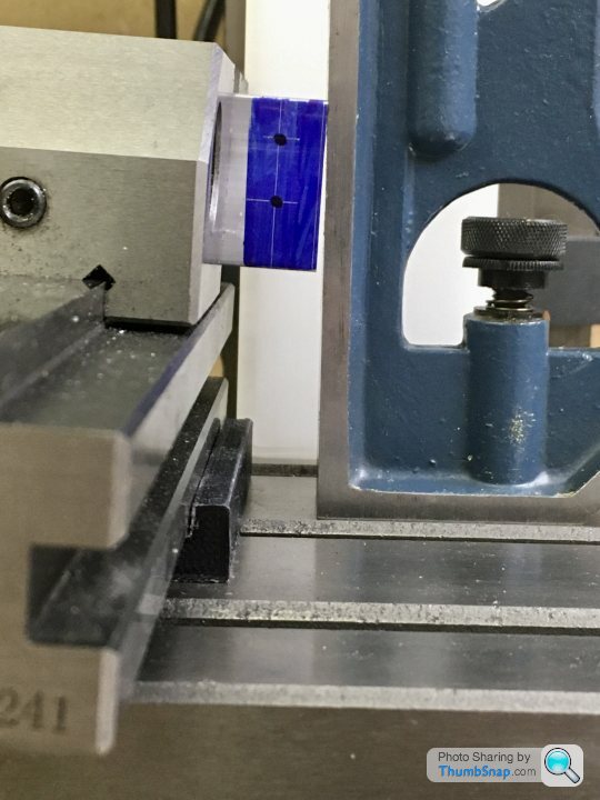
Another small thing that needed doing - milled some soft jaws for the vice out of aluminium bar. I'd started making some magnetic ones (couldn't find any good ones at a decent price), but then opted to replace the fixed steel jaws instead. Two advantages - they can't fall off at an inconvenient time, and also you can grip things right at the top edge without them pivoting themselves off the jaws. I had to make the countersinks bigger, and turn down the bolts to make sure they wouldn't touch any small diameter bar sitting within the centering grooves. Ideally they'd be aluminium screws I guess:

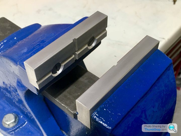
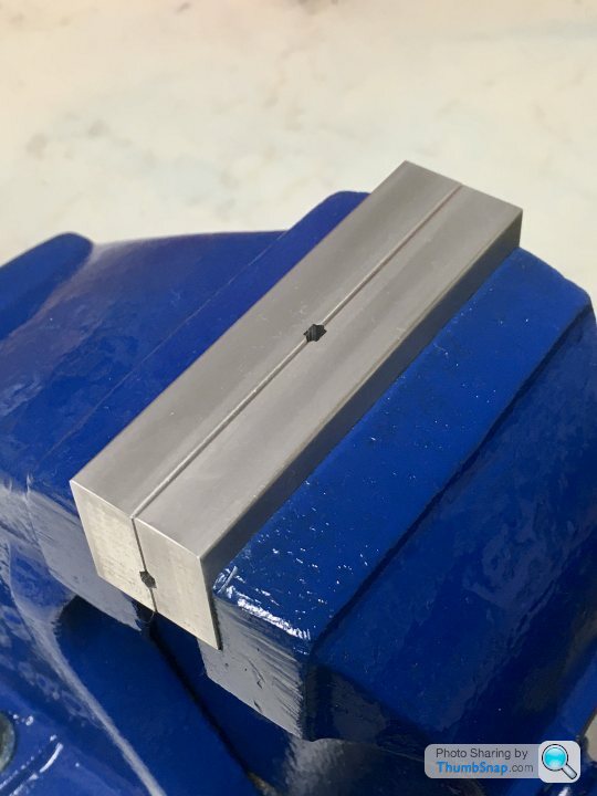

Also gave it a blow over with blue paint while I was at it.
Next...repair the home made rear toolpost I got with the lathe.
Also gave it a blow over with blue paint while I was at it.
Next...repair the home made rear toolpost I got with the lathe.
Gassing Station | Scale Models | Top of Page | What's New | My Stuff