Toylander from scratch (metal chassis and body)
Discussion


I thought I ought to start a new thread rather than clutter someone else's. Below was around a couple of months ago.
Jon_Bmw said:
I am starting to build a toylander style thing, but in metal for my two boys (4 & 2). I am not a welder or fabricator, or CAD person, so I thought I ought to try and gain some skills.
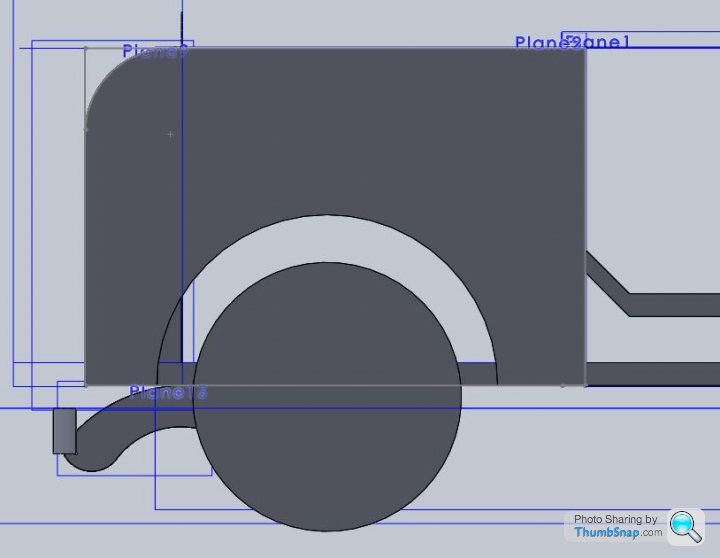
I have never used CAD before, so it took me a little time to make this;
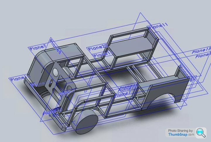
Obviously I found out about all the shortcuts like mirroring features after it was too late! My CAD level is most certainly basic, so all the straight lines of an early landrover suited me!
I finally started knocking up the chassis today.
As said, I am not a welder by trade either, so plenty of grinder action required, no, not that type!
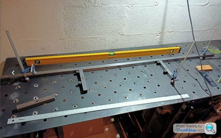
I made a couple of fixture tables at work a couple of months ago, and it really is useful for this sort of job. Its basically a table that has 16mm through holes at 100mm pitch, and M12 thread holes at an offset 12mm pitch. This makes it very useful for welding simple (and complex, if you are good!) frames. You can use a combination of 16 / M12 holes to clamp and set the part.
I need to get some nice squares lasered and fabbed up so that I can progress with the uprights and ensure it doesn't all end up completely on the piss. Partially pissed is fine.
Frame is 1.6mm thickness and will have further adhoc bracing than what is shown in the CAD.
I have a scooter, albeit with fairly knackered batteries. It seems to work ok when I hooked up some average batteries, although I am not sure it is going to cope too well with hills if I gear it up with the bigger tyres.
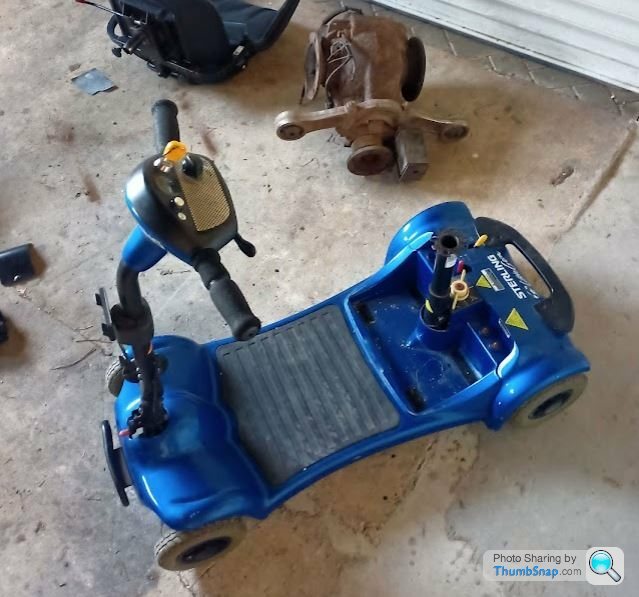
It is a single motor with a diff, but most definitely not the one shown in the photo.
I have yet to decide whether to use 0.9mm Alu rivetted to the chassis for the "bodywork" or whether to use 0.9mm mild steel and weld it...
Target weight is less than 50KG for the project, but no special attention really to achieve that. Whoops!
I have never used CAD before, so it took me a little time to make this;
Obviously I found out about all the shortcuts like mirroring features after it was too late! My CAD level is most certainly basic, so all the straight lines of an early landrover suited me!
I finally started knocking up the chassis today.
As said, I am not a welder by trade either, so plenty of grinder action required, no, not that type!
I made a couple of fixture tables at work a couple of months ago, and it really is useful for this sort of job. Its basically a table that has 16mm through holes at 100mm pitch, and M12 thread holes at an offset 12mm pitch. This makes it very useful for welding simple (and complex, if you are good!) frames. You can use a combination of 16 / M12 holes to clamp and set the part.
I need to get some nice squares lasered and fabbed up so that I can progress with the uprights and ensure it doesn't all end up completely on the piss. Partially pissed is fine.
Frame is 1.6mm thickness and will have further adhoc bracing than what is shown in the CAD.
I have a scooter, albeit with fairly knackered batteries. It seems to work ok when I hooked up some average batteries, although I am not sure it is going to cope too well with hills if I gear it up with the bigger tyres.
It is a single motor with a diff, but most definitely not the one shown in the photo.
I have yet to decide whether to use 0.9mm Alu rivetted to the chassis for the "bodywork" or whether to use 0.9mm mild steel and weld it...
Target weight is less than 50KG for the project, but no special attention really to achieve that. Whoops!
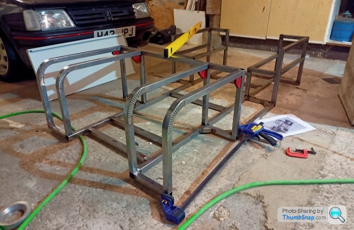
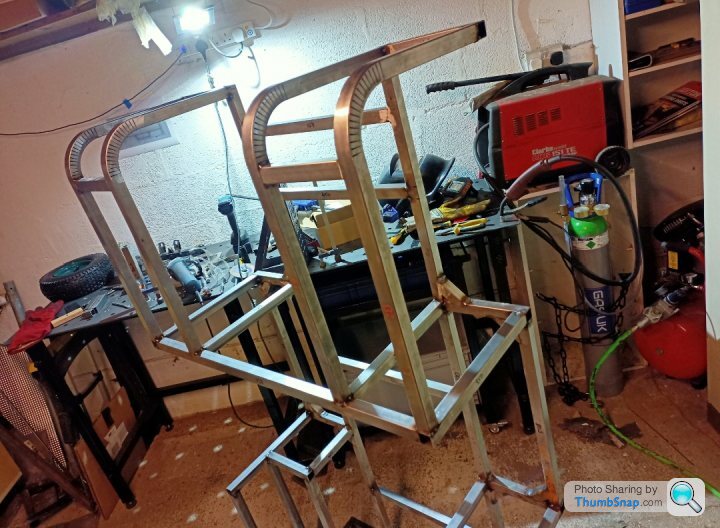
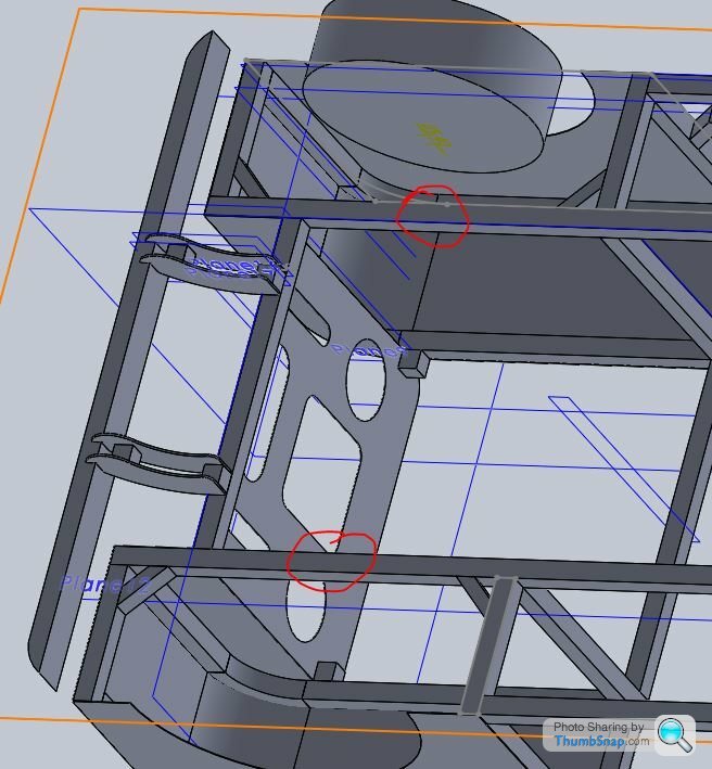
Slightly more progress on the chassis now.
I designed and made a 'little' fixture square for my table. This helped me make the uprights and keep them fairly true.
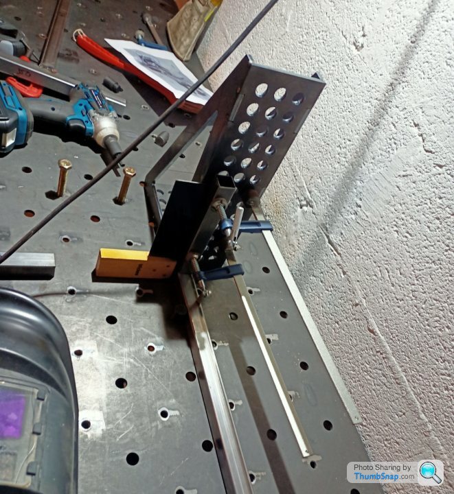
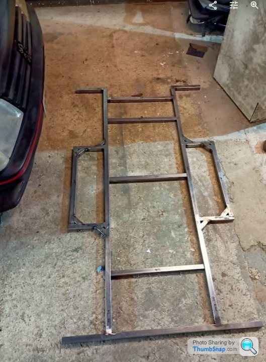
That enabled me to get a bit further on the chassis. So I ended up with this;
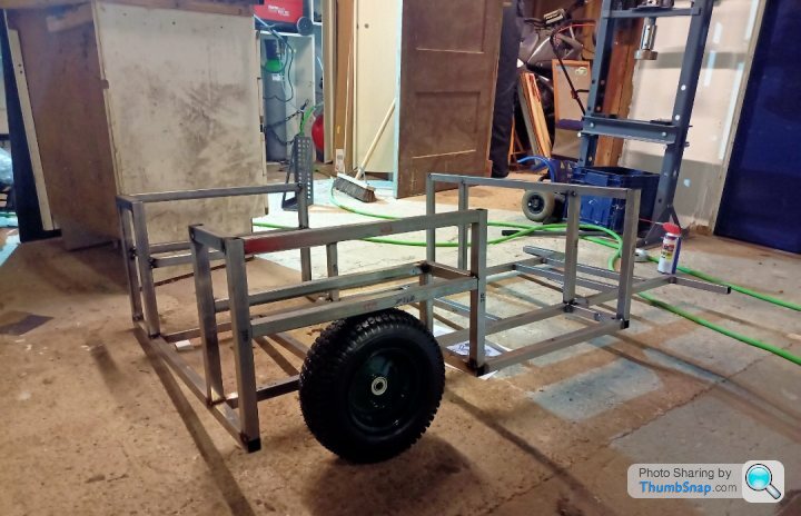
Notice that I hadn't done the difficult bit at the front with the bent box section. It had all been too easy at this point.
To tackle the bend I designed a tool to try and press it. Basically two bottom rollers would sit on the bed of the press and then the top roller had the radius I wanted and you would crank the press down to get the angle you desired. Obviously that would have been far too simple, so it didn't really work.
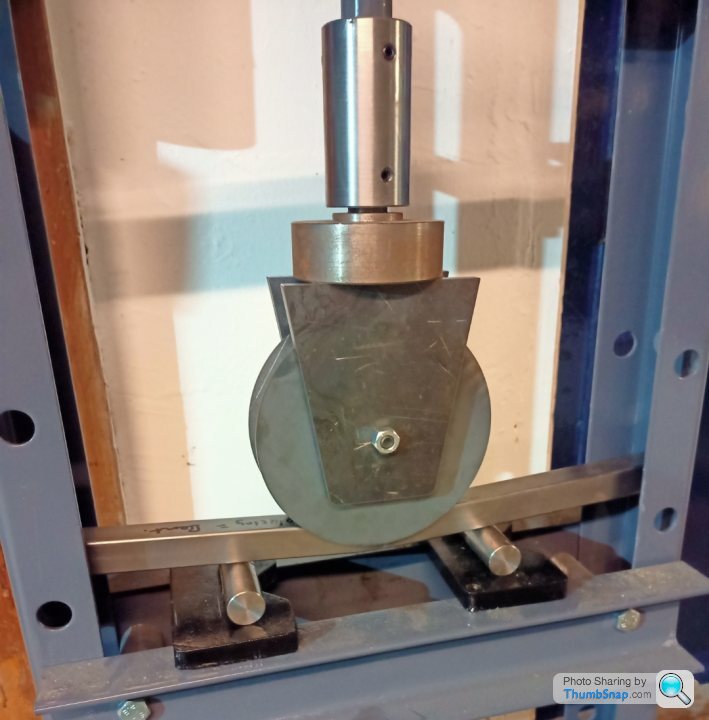
Note the bottom part of the tool isn't in place as I was too keen to try it out so just used some inch bar to roll it along. I had my safety squint on.
Alas it wasn't meant to be
The failure was so big that I didn't bother making the bottom tool up. I'm sure I'll use that very specific 10mm laser plate for something one day Mrs Jon_Bmw...
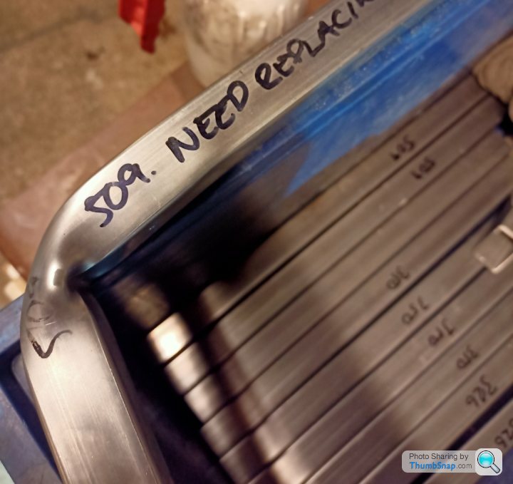
So old fashioned way, prototype:
Perfect that photo even reminds me of all the plate that's fit for the bin...
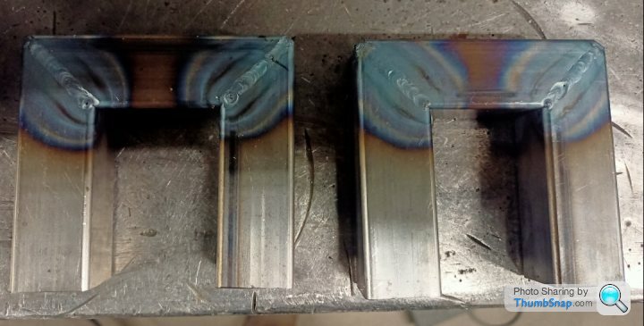
Onto the pukar job, left both ends long to trim back in situ on the chassis. I tacked two parts together and did them as matched pairs so they should be similar on each separate side and close enough between LH and RH.
Welded the inside face after popping a disc cutter down the part to try and ensure some penetration. Nope I'm still not comfortable enough to photo my welds! Trimmed them to suit. Obviously I cut one about 2mm to short. Why make the welding easy?
So they are just loosely positioned and yet to be tack welded. In fact all the uprights are just tacked at the moment. I want to get everything in place, add some strengthening pieces before blasting it with the MIG and bending everything out of shape.
I'll make sure I get lots of photos and measurements before fully welding to show anyone sad enough to care that, "yes, it was once straight, and no, I don't yet no how to avoid huge weld distortion."
That's where I am up to live as it were. Next update in many months to come I suspect. Although target for it being driveable is Christmas, I just haven't commited to which one yet.
I designed and made a 'little' fixture square for my table. This helped me make the uprights and keep them fairly true.
That enabled me to get a bit further on the chassis. So I ended up with this;
Notice that I hadn't done the difficult bit at the front with the bent box section. It had all been too easy at this point.
To tackle the bend I designed a tool to try and press it. Basically two bottom rollers would sit on the bed of the press and then the top roller had the radius I wanted and you would crank the press down to get the angle you desired. Obviously that would have been far too simple, so it didn't really work.
Note the bottom part of the tool isn't in place as I was too keen to try it out so just used some inch bar to roll it along. I had my safety squint on.
Alas it wasn't meant to be
The failure was so big that I didn't bother making the bottom tool up. I'm sure I'll use that very specific 10mm laser plate for something one day Mrs Jon_Bmw...
So old fashioned way, prototype:
Perfect that photo even reminds me of all the plate that's fit for the bin...
Onto the pukar job, left both ends long to trim back in situ on the chassis. I tacked two parts together and did them as matched pairs so they should be similar on each separate side and close enough between LH and RH.
Welded the inside face after popping a disc cutter down the part to try and ensure some penetration. Nope I'm still not comfortable enough to photo my welds! Trimmed them to suit. Obviously I cut one about 2mm to short. Why make the welding easy?
So they are just loosely positioned and yet to be tack welded. In fact all the uprights are just tacked at the moment. I want to get everything in place, add some strengthening pieces before blasting it with the MIG and bending everything out of shape.
I'll make sure I get lots of photos and measurements before fully welding to show anyone sad enough to care that, "yes, it was once straight, and no, I don't yet no how to avoid huge weld distortion."
That's where I am up to live as it were. Next update in many months to come I suspect. Although target for it being driveable is Christmas, I just haven't commited to which one yet.
Cati,
Thanks for the suggestion and offer. I'll see how much I cock up on mine and message you when I'm on the verge of ruining Christmas 2025.
Last night in the garage I pondered about how to do the front axle. Long short story I have decided to extend the width of the mobility scooter one and change the stub axle output diameter from 12mm to 16mm so it works with my bigger garden trolley wheels.
There are probably a few ways to do it, but I decided that it would be best (quickest) to sleeve over an adapter on the current 12mm stub and weld it on. I came into work with a fag packet design to give to a helpful machinest at work.
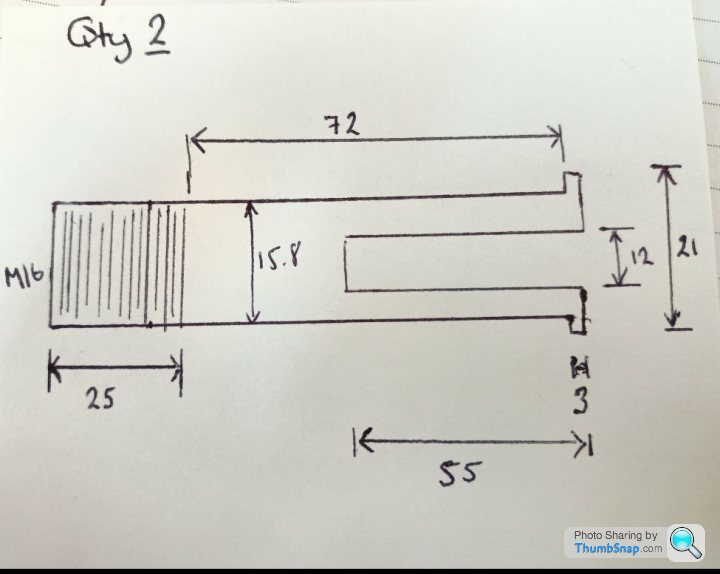
Yes, you got it, I don't work in the drawing office either.
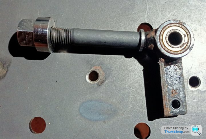
Just before I gave it to him I raided the nut and bolt cabinet and found an M16 x 110mm bolt that could be adapted and at a snip of the time of starting from a blank. My ability to accept a less than perfect solution is definitely a plus point. The shank isn't as long as ideal, but hey, its a toy, not a racer! No M16 Nut in the cabinet though. Bugger.
So imagine my surprise when 30 minutes later the machinist who was armed with two high tensile bolts and a terrible drawing on a scrap of paper brings me up this:
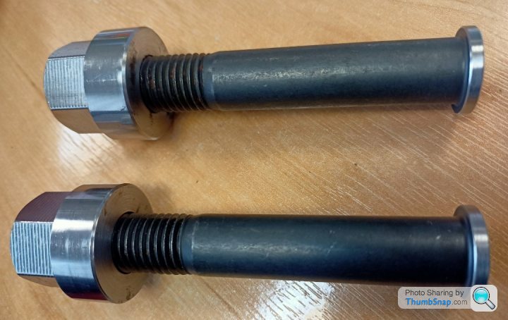
Not only has he done it straight away, but he found a couple of custom nuts he had made for a redundant job. I've always wanted centre lock wheels! They are a thing of beauty. I mean, who cares about weight, I don't have a target do I.... They have such a nice landing area that I can probably drill a hole and put a split pin in them to make sure the kids don't end up with three wheels on the wagon. It seems a shame to do that to such a visually appealing nut though. I've yet to pluck up the courage to tell the machinist that I am building a car thing, not a bike thing, so another two would be good. Let's not kill his enthusiasm on day 1.
I'll upload some pictures of the stub axle when I can and the bolt will probably make more sense.
Thanks for the suggestion and offer. I'll see how much I cock up on mine and message you when I'm on the verge of ruining Christmas 2025.
Last night in the garage I pondered about how to do the front axle. Long short story I have decided to extend the width of the mobility scooter one and change the stub axle output diameter from 12mm to 16mm so it works with my bigger garden trolley wheels.
There are probably a few ways to do it, but I decided that it would be best (quickest) to sleeve over an adapter on the current 12mm stub and weld it on. I came into work with a fag packet design to give to a helpful machinest at work.
Yes, you got it, I don't work in the drawing office either.
Just before I gave it to him I raided the nut and bolt cabinet and found an M16 x 110mm bolt that could be adapted and at a snip of the time of starting from a blank. My ability to accept a less than perfect solution is definitely a plus point. The shank isn't as long as ideal, but hey, its a toy, not a racer! No M16 Nut in the cabinet though. Bugger.
So imagine my surprise when 30 minutes later the machinist who was armed with two high tensile bolts and a terrible drawing on a scrap of paper brings me up this:
Not only has he done it straight away, but he found a couple of custom nuts he had made for a redundant job. I've always wanted centre lock wheels! They are a thing of beauty. I mean, who cares about weight, I don't have a target do I.... They have such a nice landing area that I can probably drill a hole and put a split pin in them to make sure the kids don't end up with three wheels on the wagon. It seems a shame to do that to such a visually appealing nut though. I've yet to pluck up the courage to tell the machinist that I am building a car thing, not a bike thing, so another two would be good. Let's not kill his enthusiasm on day 1.
I'll upload some pictures of the stub axle when I can and the bolt will probably make more sense.
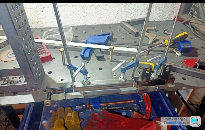
Front wheel arch pieces tack welded on:
Look at the state of the workbench in the background. I must spend more time looking for the right tool than actually using it.
Welders look away now:
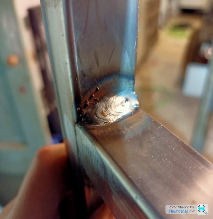
So many issues with my welding skills, but too little time to address them all. Obviously I photographed the best ones I did too! Any thoughts of a welding Instagram page might have to wait 10 years until I finally get it.
Next jobs:
- Chassis Bracing
- Front axle extending / Mounting
Look at the state of the workbench in the background. I must spend more time looking for the right tool than actually using it.
Welders look away now:
So many issues with my welding skills, but too little time to address them all. Obviously I photographed the best ones I did too! Any thoughts of a welding Instagram page might have to wait 10 years until I finally get it.
Next jobs:
- Chassis Bracing
- Front axle extending / Mounting
So an early night watching the football with a couple of bit of scrap papers on my lap ended up with this;
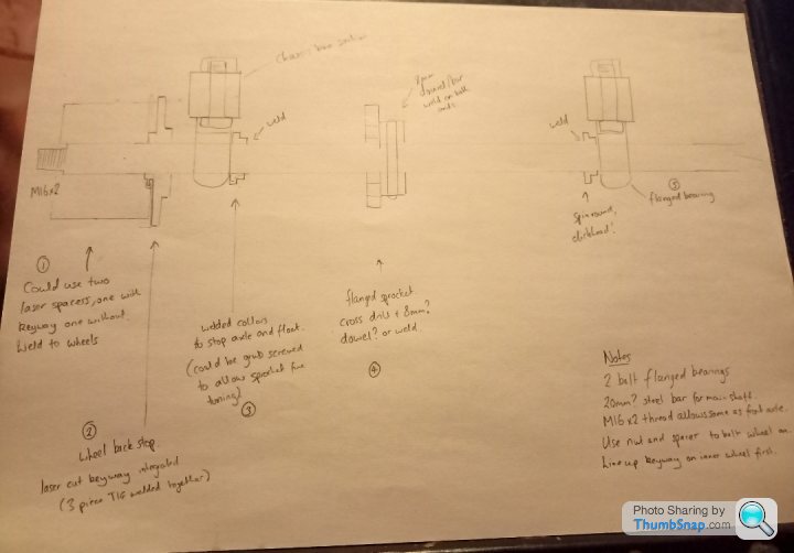
So it's a pretty rudimentary rear axle design, probably with numerous errors I have yet to find and will come across when I buy all the bits...
Fast forward a week or so and I thought I should try and order some bits;
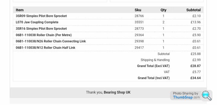

I have tried ordering some jaw couplings rather than my molested laser cut effort on my 'drawing.' I found them whilst perusing the bearing shop website. I have definitely got to that age where a online shop like that is interesting! My dad used to love the "towsure" catalogue 20 years ago and I never really understood it. I do now!
Back to jaw couplings... I didn't really know they existed until I was on the website. They look like this;
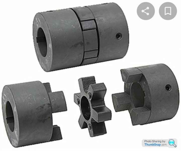
My plan is machine the OD down from 35 to 34.5 so it slots inside my trailer wheels that have had there own integral bearing knocked out. I weld one part to the wheel and the other to the axle. The little spider bit might take away any harshness on and off the throttle but I can't claim that I actually designed that in, they just come like it!
Annoyingly the max ID that you can bore them out to is 19mm, so I'll either turn the axle down to 19mm from 20, or most likely I will ignore the technical parameters someone spent time designing and hog it out to 20mm
Whether it all works is anyone's guess! The bits haven't turned up yet.
I've disconnected the mobility scooter motor from its open diff. I think an open diff is probably going to become a problem with rutted byways with my non suspension rear axle. Why no rear suspension you may ask? The answer, too complicated for my simplistic brain! Annoyingly the output shaft on the motor is less than 10mm in length but I reckon I can just about get a sprocket on there... Time will tell. I also need to design a motor mount at some point. I'm thinking laser cut C shaped pieces with a base that I can bolt to the frame that allows adjustment for and aft to get the chain tension about right. I am not planning to run a tensioner at the moment as that adds more complexity.... anyone seeing a pattern developing here.
So it's a pretty rudimentary rear axle design, probably with numerous errors I have yet to find and will come across when I buy all the bits...
Fast forward a week or so and I thought I should try and order some bits;
I have tried ordering some jaw couplings rather than my molested laser cut effort on my 'drawing.' I found them whilst perusing the bearing shop website. I have definitely got to that age where a online shop like that is interesting! My dad used to love the "towsure" catalogue 20 years ago and I never really understood it. I do now!
Back to jaw couplings... I didn't really know they existed until I was on the website. They look like this;
My plan is machine the OD down from 35 to 34.5 so it slots inside my trailer wheels that have had there own integral bearing knocked out. I weld one part to the wheel and the other to the axle. The little spider bit might take away any harshness on and off the throttle but I can't claim that I actually designed that in, they just come like it!
Annoyingly the max ID that you can bore them out to is 19mm, so I'll either turn the axle down to 19mm from 20, or most likely I will ignore the technical parameters someone spent time designing and hog it out to 20mm
Whether it all works is anyone's guess! The bits haven't turned up yet.
I've disconnected the mobility scooter motor from its open diff. I think an open diff is probably going to become a problem with rutted byways with my non suspension rear axle. Why no rear suspension you may ask? The answer, too complicated for my simplistic brain! Annoyingly the output shaft on the motor is less than 10mm in length but I reckon I can just about get a sprocket on there... Time will tell. I also need to design a motor mount at some point. I'm thinking laser cut C shaped pieces with a base that I can bolt to the frame that allows adjustment for and aft to get the chain tension about right. I am not planning to run a tensioner at the moment as that adds more complexity.... anyone seeing a pattern developing here.
Thanks for the advice. I had seen your thread on here and was very impressed with the level of detail. I am pretty sure this one will end up a bit of a lash up!
This one is going to be a bit wider than a traditional toylander from the measurements I have seen. The cad above shows the wheels quite wide in the arch as well which I need to get a 45degree angle on the wheels which should help stability. I might get it rolling on its wheels put some weight in it and try and push it over Or give it to the child that's been whining the most that day to be the crash test dummy.
This one is going to be a bit wider than a traditional toylander from the measurements I have seen. The cad above shows the wheels quite wide in the arch as well which I need to get a 45degree angle on the wheels which should help stability. I might get it rolling on its wheels put some weight in it and try and push it over
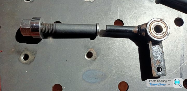
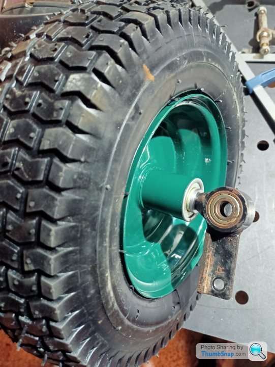
Or give it to the child that's been whining the most that day to be the crash test dummy. I nipped into the garage this evening with a rough plan of extending the mobility scooter front axle to the wheel track I wanted.
I chopped the original part into three and added my extension pieces in. The central part has a bush in it which secured the axle on the mobility scooter allowing a minimal amount of "suspension" travel. Extending it the way I have allows me to keep that option if I want to utilise it.
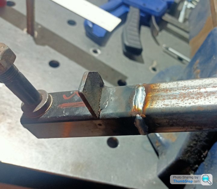
Nope, you are quite correct, the welding is not getting better. Add some lazy prep work, by not removing the paint properly, and it looks like a Friday afternoon job by Stevie Wonder. Still, I bevelled it so she'll grind back flush at a later date.
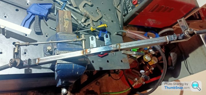
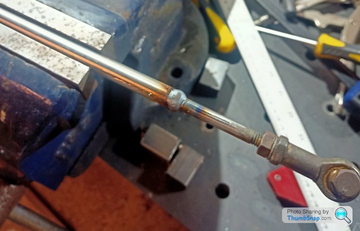
Extending the main beam meant extending the tie rods that keep the two wheels on a similar angle. This was 8mm rod, now any sensible person would have made a new longer 8mm rod and die cut the threads on the end. With the possibility that it would need LH and RH threads cut and combined with the fact I didn't have 8mm bar or those dies I cut it in half, sleeved over a 12*1.5 wt tube over it and Mig welded it together. Yes the original bar is MS and the tube SS and the weld wire MS. Whoops. I can live with it!
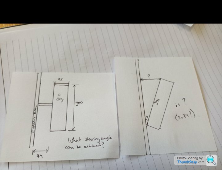
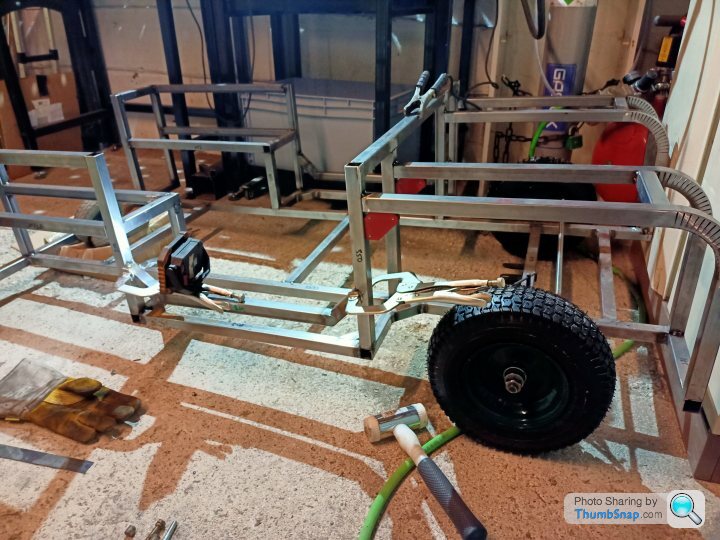
Test fit time. I did* some trig with a mate from work to figure out what distance I needed to make the front beam to get a 45 degree angle on the wheels. Fortunately it seemed to have worked out pretty well. If you squint it looks close to 45 degrees, to me anyhow!
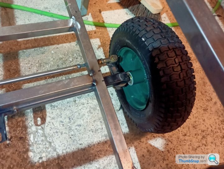
N.B My involvement in the trig was sending him a fag packet sketch over WhatsApp and asking him to work out what I thought I didn't have enough info for. Alas he worked it out instantly. Prick.
This is what I sent him along with the question what distance do I need to achieve a 45 deg angle. What do you think it is? It's so simple to work out when you know it. Cheers JH.
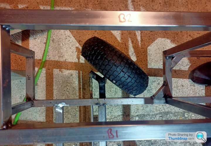
Roughed out what it would look like if I mounted the axle below the chassis rails;
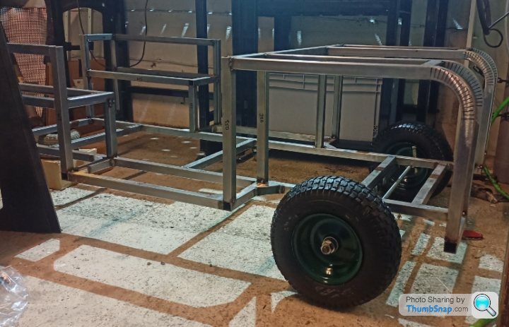
The wheels look a touch small there, but beggars can't be choosers and I paid 50 quid for those wheels so that's what it's getting. Ground clearance to main chassis rails is 8inch, so I may, just may drop the wheels into the arches more by placing the axle on top of the chassis and lose a couple of inches of ground clearance. Or I could drop the laser cut wheel arches down a bit more...Decisions for another day.
I chopped the original part into three and added my extension pieces in. The central part has a bush in it which secured the axle on the mobility scooter allowing a minimal amount of "suspension" travel. Extending it the way I have allows me to keep that option if I want to utilise it.
Nope, you are quite correct, the welding is not getting better. Add some lazy prep work, by not removing the paint properly, and it looks like a Friday afternoon job by Stevie Wonder. Still, I bevelled it so she'll grind back flush at a later date.
Extending the main beam meant extending the tie rods that keep the two wheels on a similar angle. This was 8mm rod, now any sensible person would have made a new longer 8mm rod and die cut the threads on the end. With the possibility that it would need LH and RH threads cut and combined with the fact I didn't have 8mm bar or those dies I cut it in half, sleeved over a 12*1.5 wt tube over it and Mig welded it together. Yes the original bar is MS and the tube SS and the weld wire MS. Whoops. I can live with it!
Test fit time. I did* some trig with a mate from work to figure out what distance I needed to make the front beam to get a 45 degree angle on the wheels. Fortunately it seemed to have worked out pretty well. If you squint it looks close to 45 degrees, to me anyhow!
N.B My involvement in the trig was sending him a fag packet sketch over WhatsApp and asking him to work out what I thought I didn't have enough info for. Alas he worked it out instantly. Prick.
This is what I sent him along with the question what distance do I need to achieve a 45 deg angle. What do you think it is? It's so simple to work out when you know it. Cheers JH.
Roughed out what it would look like if I mounted the axle below the chassis rails;
The wheels look a touch small there, but beggars can't be choosers and I paid 50 quid for those wheels so that's what it's getting. Ground clearance to main chassis rails is 8inch, so I may, just may drop the wheels into the arches more by placing the axle on top of the chassis and lose a couple of inches of ground clearance. Or I could drop the laser cut wheel arches down a bit more...Decisions for another day.
The box of bits from the bearing shop turned up a couple of weeks back and have sat on my desk for a while looking sorry for themselves.
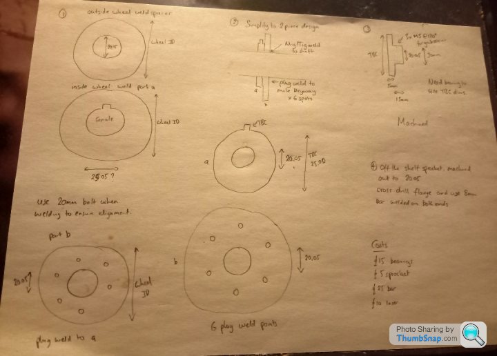
So I hashed up a bit of a plan for the axle.
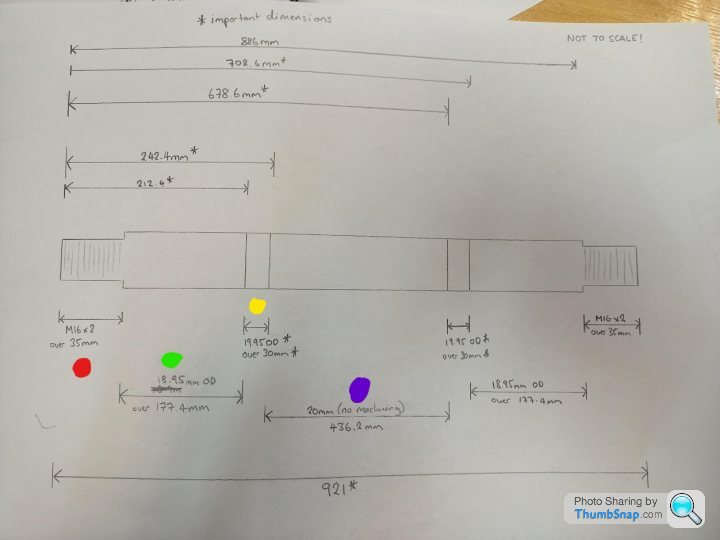
Purple dot: This is where the 16tooth sprocket will sit
Yellow dot: This is where the flanged bearings will mount to the chassis
Green dot: This is where the jaw coupling will sit
Red dot: This is where the wheel is going to be secured with one of those nice fancy nuts.
I'm expecting much criticism of the drawing, no tolerances, no datums, one view only etc. What can I say, i'm special and my machinist buddy will do some magic I am sure.
As with all good plans, we tore most of it up when I had the parts in my hand and was talking to my friendly machinist buddy!
The yellow dot area didn't need .05 taken off, it was me being a wally with the flanged bearing and not getting it square!
The green dot area is actually going to end up around 16.5mm. The reason is that if we made it my original size the spider part of the jaw coupling (damper piece) would have been completely bored out and I would have lost each of the 4 "legs." I would imagine I am not really using the jaw coupling how it was intended and the spider part would not normally be bored out to fit on a shaft... So if I drill it out smaller it will hopefully remain on the shaft.
He will drill out the Jaw couplings to around 16.5mm then turn the "green dot" portion of the bar down to a nice tight fit. Easy huh, especially because I don't have to do it.
I also thought that perhaps I should try and keep some track of costs of the job. Lets just say I am not going to account anything for my labour, or else I could have bought a real car for this amount. It does show how costs spiral and I have had lots of things and peoples expertise for free.
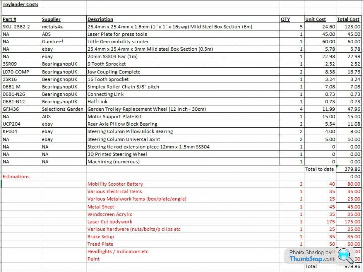
I'm selling it to myself that if I had bought a ready made toylander, whilst infinitely easier it would probably be around £3k and it would be made of wood and who wants wood?
So I hashed up a bit of a plan for the axle.
Purple dot: This is where the 16tooth sprocket will sit
Yellow dot: This is where the flanged bearings will mount to the chassis
Green dot: This is where the jaw coupling will sit
Red dot: This is where the wheel is going to be secured with one of those nice fancy nuts.
I'm expecting much criticism of the drawing, no tolerances, no datums, one view only etc. What can I say, i'm special and my machinist buddy will do some magic I am sure.
As with all good plans, we tore most of it up when I had the parts in my hand and was talking to my friendly machinist buddy!
The yellow dot area didn't need .05 taken off, it was me being a wally with the flanged bearing and not getting it square!
The green dot area is actually going to end up around 16.5mm. The reason is that if we made it my original size the spider part of the jaw coupling (damper piece) would have been completely bored out and I would have lost each of the 4 "legs." I would imagine I am not really using the jaw coupling how it was intended and the spider part would not normally be bored out to fit on a shaft... So if I drill it out smaller it will hopefully remain on the shaft.
He will drill out the Jaw couplings to around 16.5mm then turn the "green dot" portion of the bar down to a nice tight fit. Easy huh, especially because I don't have to do it.
I also thought that perhaps I should try and keep some track of costs of the job. Lets just say I am not going to account anything for my labour, or else I could have bought a real car for this amount.
It does show how costs spiral and I have had lots of things and peoples expertise for free. I'm selling it to myself that if I had bought a ready made toylander, whilst infinitely easier it would probably be around £3k and it would be made of wood and who wants wood?
Hard-Drive said:
Jon, I know on my build I went a bit crazy on the scale details, altering the Toylander plans by taking measurements off my own full sized Defender and scaling to suit, but I really would think hard about those wheels. As a long time Land Rover owner stuff that's well out of proportion does tend to jump out at me a bit, and I do think the wheels look way too small for your build, especially once you have the wing "skins" on.
You can get 4.80/4.00 wheels pretty cheaply, and if you sell your existing wheels you'll cover a fair chunk of the cost. You're going to so much effort with this, it seems a shame to compromise the overall look of the thing with the wheels and/or ground clearance. Ask any car designer what makes a car "look" right or wrong and it's the wheels to body ratio.
Wheel size will affect speed, ground clearance (which trust me is important on these), but at the design stage you'll need to factor in gear ratio and steering lock.
Also, how is the front "suspension" bush working? Is it just a rudimentary elastomer shock absorber, or does it allow some tractor axle style swing? I'd really recommend a tractor axle as will make a huge difference keeping all 4 wheels on the ground.
And finally, is the back axle just solid? You'll either need some kind of diff arrangement, or make it 1 wheel drive. It won't turn properly with a solid back axle, especially as you have quite a lot of steering angle available (of course it's entirely possible I've misunderstood your drawings!)
Great work though, fab fabbing skills there!
I think you are quite correct about the scale of the wheels to body. I think I need to rehome this thread in the "not scale models section!" I really should have looked at more actual landrovers rather than making my model off a few different toylander models I had seen. Whoops! Is it becoming a bit obvious that I am not a land rover man? You can get 4.80/4.00 wheels pretty cheaply, and if you sell your existing wheels you'll cover a fair chunk of the cost. You're going to so much effort with this, it seems a shame to compromise the overall look of the thing with the wheels and/or ground clearance. Ask any car designer what makes a car "look" right or wrong and it's the wheels to body ratio.
Wheel size will affect speed, ground clearance (which trust me is important on these), but at the design stage you'll need to factor in gear ratio and steering lock.
Also, how is the front "suspension" bush working? Is it just a rudimentary elastomer shock absorber, or does it allow some tractor axle style swing? I'd really recommend a tractor axle as will make a huge difference keeping all 4 wheels on the ground.
And finally, is the back axle just solid? You'll either need some kind of diff arrangement, or make it 1 wheel drive. It won't turn properly with a solid back axle, especially as you have quite a lot of steering angle available (of course it's entirely possible I've misunderstood your drawings!)
Great work though, fab fabbing skills there!
I have a few options, none are that palatable.
1) I could reduce the height of the upstands by 20-30% but the chances of me getting that lot square again is probably zero...
2) Increase wheel size fairly drastically, but I will need to change the rear sprocket size....and £50 wheels....

3) Realise that what I have designed is not really that close to any land rover and just accept it!
In Cad, whilst it doesn't look like a series 1 (now I have actually googled some pictures!), I don't think it looks too bad, but the wheel tyre doesn't look exactly like CAD as it has quite a radius across the thread width.
Option 3 is looking sorely tempting... I never intended, or have the patience, to get it to be a great replica. Hopefully the 4 and 2 year old will forgive me when they grow up. Or run me over with the undersized wheels.
The front axle I haven't completely made my mind up on yet. I am trying to get the rear sorted to loosely bolt up before committing to the front. Ideally it would be the tractor style (or what I think you are referring to) where the axle pivots around a single bolted point in the Y0 car line. Now in my infinite wisdom I didn't CAD the axle, because complicated! So that has left me with a slight issue that if I want to use the tractor style pivot method, I would need to lower the mounting point down or else the pivot would hit the main chassis cross members.
The lower I mount it, the more odd the wheels look. I'm stuck in a viscous circle with the way out being lots more time to cure. Ha.
So currently, I am taking the pragmatic view point of, "lets worry about that later!"
Rear axle is going to be solid and both wheels driven, I will see what it is like and then probably have to re-do it at some point. I am hoping the relatively thin contact points on the rear tyres will mean the rear axle skipping will be slightly less pronounced... The whole front and rear axle design will probably get carved up at some point. Gear ratio should be the same as the mobility scooter if I got my maths right. Famous last words.
So at this rate, solid front an rear axle, but I think the toylanders are pretty much like that from what I could see. Let them have a go, see what breaks and doesn't work and make good. Snagging list could be extensive!
Have you got some photos of your setup, especially with regards to the front and rear axle, that I errr, could take some inspiration from (shamelessly copy)? Thanks for the help and advice, I will actually try and follow some of it one day when I realise my lash up is not working too well!
Many things to learn, but the main thing is I am still enjoying it. Phew.
Someone else's viewpoints are always good, especially someone who has been there, done it and got the T-shirt. I'm having to balance the end result over how much time I spend in the garage otherwise I would probably do everything you said. I really wanted full suspension and then I realised that I would need to double the budget and double the time. I hope the kids can use it OK on some of the more car suitable byways on Salisbury Plain.
I'm probably (definitely?) being thick but what advantage does the front swinging really entail if the rear is solid? There must be a bit as the little mobility scooter had the same setup. This could be fairly simply solved, by notching the chassis rail once the rest is all welded up. Not what you'd want on a racer, but...
I can't carry the transaxle across from the mobility scooter for a variety of reasons, the gearing would be wrong, the driveshaft width to narrow and diameter too small.
If Toylander do a twin motor, then surely that is like a non diff axle? Or have they got some clever programming in it? I thought the locked rear axle would be less likely to get stuck, if somewhat unsympathetic to general turning principles.
The 205 that you can see in the background of one of the pictures actually has a plate LSD which, whilst still technically a differential, has a very aggressive lockup so I am used to the scrubbing/banging and embarrassing passer-by looks. That works ok and is FWD.
The wheels are 12" vs 14.75 from toylander, the thing that is hurting it, is I am scaled up by approx 20% I guess. I don't really know as I don't have toylander plans and it seemed unjust to buy them and copy everything! I actually think series 1 land rovers look a bit odd (sorry! ) with the wheels looking massively oversized for the vehicle, but understand why they did it.
I'm still tempted to cut the uprights down and then redraw the panels. Anyone got some spare enthusiasm in a jar?
I'm probably (definitely?) being thick but what advantage does the front swinging really entail if the rear is solid? There must be a bit as the little mobility scooter had the same setup. This could be fairly simply solved, by notching the chassis rail once the rest is all welded up. Not what you'd want on a racer, but...
I can't carry the transaxle across from the mobility scooter for a variety of reasons, the gearing would be wrong, the driveshaft width to narrow and diameter too small.
If Toylander do a twin motor, then surely that is like a non diff axle? Or have they got some clever programming in it? I thought the locked rear axle would be less likely to get stuck, if somewhat unsympathetic to general turning principles.
The 205 that you can see in the background of one of the pictures actually has a plate LSD which, whilst still technically a differential, has a very aggressive lockup so I am used to the scrubbing/banging and embarrassing passer-by looks.
That works ok and is FWD.The wheels are 12" vs 14.75 from toylander, the thing that is hurting it, is I am scaled up by approx 20% I guess. I don't really know as I don't have toylander plans and it seemed unjust to buy them and copy everything! I actually think series 1 land rovers look a bit odd (sorry!
) with the wheels looking massively oversized for the vehicle, but understand why they did it. I'm still tempted to cut the uprights down and then redraw the panels. Anyone got some spare enthusiasm in a jar?
I think I now understand how your axle works and I can see the benefits. Ironically it's a lot more simplistic. Does it not get stuck wheel spinning ever? I guess it's overall weight is quite low and as long as you have a bit of momentum it's probably fine.
Trying to get the swinging front axle is something I will try and do. The live axle I guess offsets the lack of suspension at the rear, my main concern was wheel spinning one wheel on uneven ground.
The comment about the 205 was purely a reference that a fixed axle does work with a different set of drawbacks. I don't think I'm under any illusions that it's perfect but I don't think my lads are going to be rockclimbing the thing either. Mostly flat byways and the garden.
Interesting point about the weight of the steering, something else I hadn't really considered. If I offset the motor and it all goes to s t I can always mount another couple of pillar bearings and disc cut the live axle. Nothing like a bodge with an angle grinder.
Thanks for all the feedback. More time designing next time and less cutting.
Trying to get the swinging front axle is something I will try and do. The live axle I guess offsets the lack of suspension at the rear, my main concern was wheel spinning one wheel on uneven ground.
The comment about the 205 was purely a reference that a fixed axle does work with a different set of drawbacks. I don't think I'm under any illusions that it's perfect but I don't think my lads are going to be rockclimbing the thing either. Mostly flat byways and the garden.
Interesting point about the weight of the steering, something else I hadn't really considered. If I offset the motor and it all goes to s
t I can always mount another couple of pillar bearings and disc cut the live axle. Nothing like a bodge with an angle grinder. Thanks for all the feedback. More time designing next time and less cutting.
Thick OP here...
With the swinging front axle (central bolt method), with the driver offset what stops it naturally leaning over? The same for going round corners.
What travel at the wheel end do you have Hard drive. I am thinking about 100mm.
Am I overthinking it, or would it be better with some valve springs or something to try and offset the weight of the driver but allow for travel when hitting bumps. Can you tell I am not an engineer, Cad guy or fabricator yet? Just wait until we get to the electronics
Brill, thanks for that. Without first hand experience or these things it's hard to appreciate what actually happens in the real world. I don't have any vehicles to poke about with.
So to accommodate the swinging axle and keep the approximate ride height I have I need to notch the chassis rails.
I knobbed these up at work in my half an hour lunch break. Benefits, chop saw thats good for 45's, TIG weld plant. Drawbacks, all the experts piss taking my welding. Ha.
I will use a couple of strengtheners each side of the uprights to try and support them better. Less than an ideal solution, but "it'll do."
I think I will drop the front wing box sections curing the issue of having to mount an additional bulkhead and making it slightly more authentic. The rear I will see how we get on....
I did some basic trig earlier and calculated that I needed 54mm clearance in the chassis rails to get 100mm of upward movement. I've gone bigger than that so I can stick a rubber dobber in there as a bump stop and tune it slightly.
I've checked the clearance to the wing panels and it just clears (theoretically). I need to remember to alter the wing panels in cad to match the "dropped" front end but maintain the wheel arch height. That is definitely something I'm going to forget to do!
"It'll do" is the new project Moto!
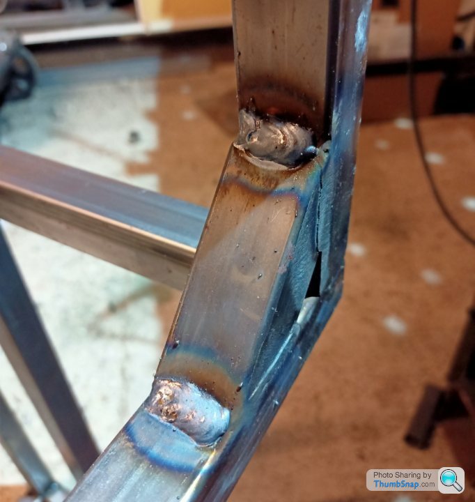
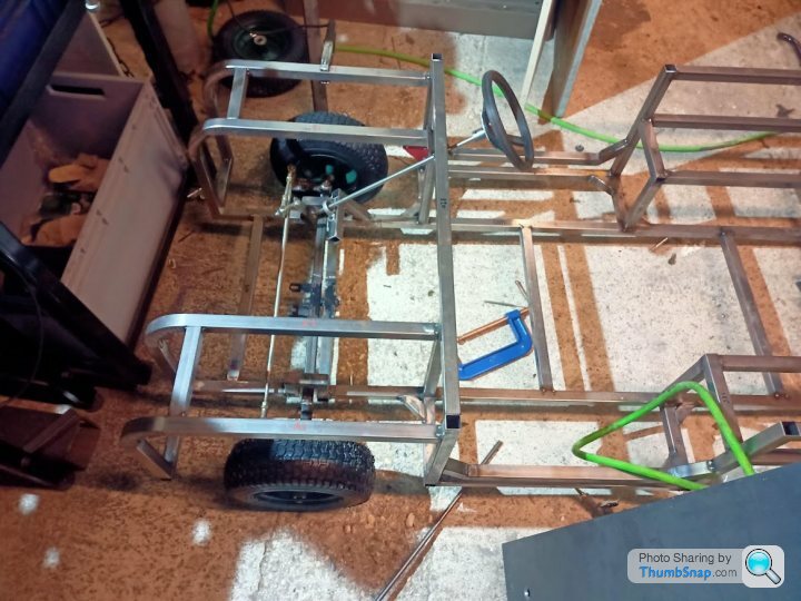
So 3 hours, predominantly procrastinating, in the garage last night ended up with the following progress:
Dropped the front wings down by 2" and gained the bulkhead for the W/screen to mount to. It didn't take too long. Added in supports for the main tub, designed in a way so that they arn't going to get too much in the way of the doors, if I decide to have doors.
Then notched the chassis leg for the tractor style front axle. The chassis is under a bit of tension so when you cut it the rails wonder quite a bit and that was with some temporary supports near the area as well.
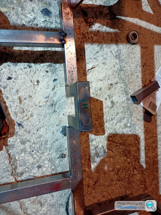
Figure out which side has moved, then bodge:
All welded up:
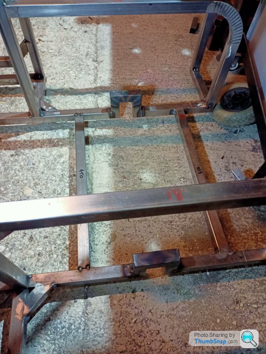
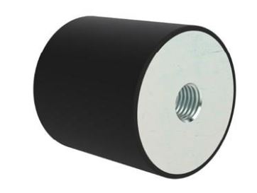
I will weld the front cross bar under the chassis now, then bolt the swinging axle to that. It will swing into those nice notches (fingers crossed!) and the swing angle I can tweak by fitting a couple of rubber dobbers to the notched part on a bolt:
Also, I am starting to think about the steering column. It will probably be a couple of pillow bearings one near the bulkhead and another near the tie rod with a UJ to take out any minor misalignment:
Until next time.
Dropped the front wings down by 2" and gained the bulkhead for the W/screen to mount to. It didn't take too long. Added in supports for the main tub, designed in a way so that they arn't going to get too much in the way of the doors, if I decide to have doors.
Then notched the chassis leg for the tractor style front axle. The chassis is under a bit of tension so when you cut it the rails wonder quite a bit and that was with some temporary supports near the area as well.
Figure out which side has moved, then bodge:
All welded up:
I will weld the front cross bar under the chassis now, then bolt the swinging axle to that. It will swing into those nice notches (fingers crossed!) and the swing angle I can tweak by fitting a couple of rubber dobbers to the notched part on a bolt:
Also, I am starting to think about the steering column. It will probably be a couple of pillow bearings one near the bulkhead and another near the tie rod with a UJ to take out any minor misalignment:
Until next time.
There has been minimal progress over the last few weeks. I blame the miserable weather and cold garage, but its probably just me lacking enthusiasm.
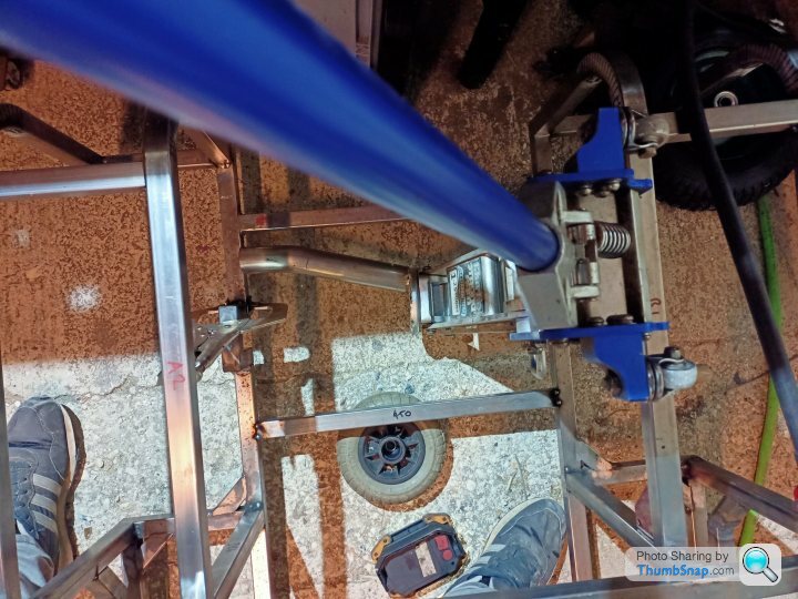
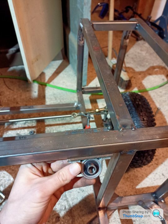
I welded up the tractor axle support bar and bolted that up. I had to extend the mobility scooter King pin so the steering arm misses my chassis notches. They still need slightly taller spacers but I didn't have any M8 x 130 bolts kicking around. Who does!
You can also see the steering column is test fitted there. I need to triangulate the bottom pillar bearing support but it actually works.
On larger axle articulation, the steering tie rods contact the chassis notches, so the increased spacers should help there. I am yet to fit the rubber dobbers to limit the travel.
3D printed steering wheel will probably be replaced by a metal/3D printed hybrid to offer more strength, but it might do a test drive. Its better than a mole grip right?
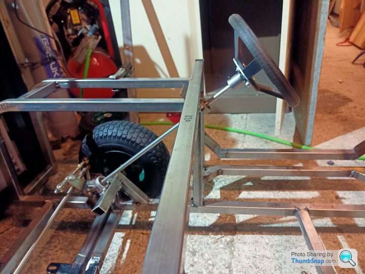
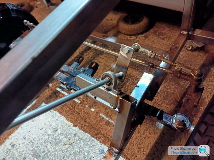
A bonus of the pillar bearings and rose joints on the steering rods is that you can fine tune the height of the column by around 100mm and then lock it off using the grub screws on the bearings. It might come in useful as the kids get older. I won't pretend that I designed that in...
The rear axle drawing is still with my machinist colleague, some normal paid work is getting in the way. WTF?
The rear axle would be nice to design the motor mount and other gubbins in that area, but in the spirit of this project I'll have to do without.
So, laser cut supports:
Tack them for the drilling the through holes:
This looks safe, safety squint on:
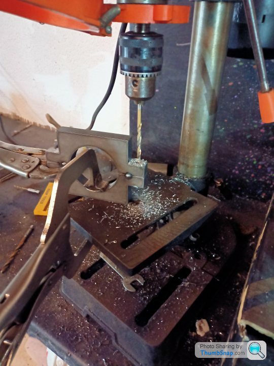
3mm plate with 12mm oversize holes in, then bish, bash, bosh I welded the mounts onto it. Ideally I could have turned the welder up some more, but I blew a fuse last week with it on its max setting, so I laid some horribly cold welds down.
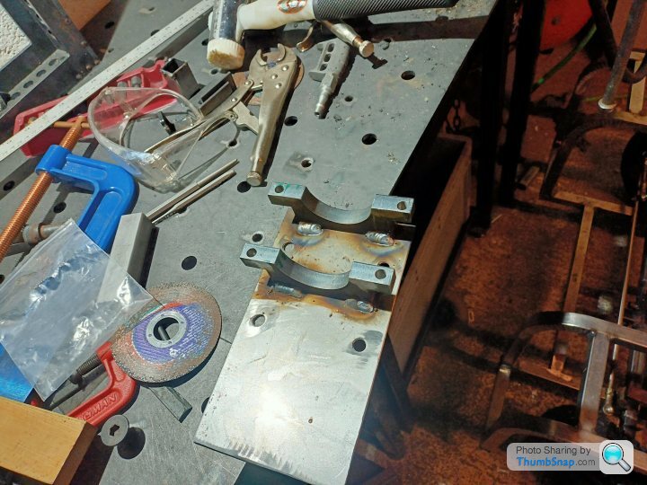
It would have been nice if the holes were central, but as my dad says, "you can't have everything." Much like a clean work surface.

The 12mm holes in the plate should allow some adjustment in X and Y to adjust chain slack. Big penny style washers will be used with M8 bolts I reckon.
More adjustments are probably likely when I get the rear axle from the machinist. That'll do.
I welded up the tractor axle support bar and bolted that up. I had to extend the mobility scooter King pin so the steering arm misses my chassis notches.
They still need slightly taller spacers but I didn't have any M8 x 130 bolts kicking around. Who does!You can also see the steering column is test fitted there. I need to triangulate the bottom pillar bearing support but it actually works.
On larger axle articulation, the steering tie rods contact the chassis notches, so the increased spacers should help there. I am yet to fit the rubber dobbers to limit the travel.
3D printed steering wheel will probably be replaced by a metal/3D printed hybrid to offer more strength, but it might do a test drive. Its better than a mole grip right?
A bonus of the pillar bearings and rose joints on the steering rods is that you can fine tune the height of the column by around 100mm and then lock it off using the grub screws on the bearings. It might come in useful as the kids get older. I won't pretend that I designed that in...
The rear axle drawing is still with my machinist colleague, some normal paid work is getting in the way. WTF?
The rear axle would be nice to design the motor mount and other gubbins in that area, but in the spirit of this project I'll have to do without.
So, laser cut supports:
Tack them for the drilling the through holes:
This looks safe, safety squint on:
3mm plate with 12mm oversize holes in, then bish, bash, bosh I welded the mounts onto it. Ideally I could have turned the welder up some more, but I blew a fuse last week with it on its max setting, so I laid some horribly cold welds down.
It would have been nice if the holes were central, but as my dad says, "you can't have everything." Much like a clean work surface.
The 12mm holes in the plate should allow some adjustment in X and Y to adjust chain slack. Big penny style washers will be used with M8 bolts I reckon.
More adjustments are probably likely when I get the rear axle from the machinist. That'll do.
I had 2 weeks off over Christmas, so as expected, zero progress with the toylander!
I took the oldest to Haynes motor museum over the holiday and they had a series 3 there which I took a few photos of as a bit of a guide. The good thing with a series 3 is that the rear tub is higher than the front wings! So I'm now aiming for that as it matches more closely what I have done so far. Sorry landrover lovers!
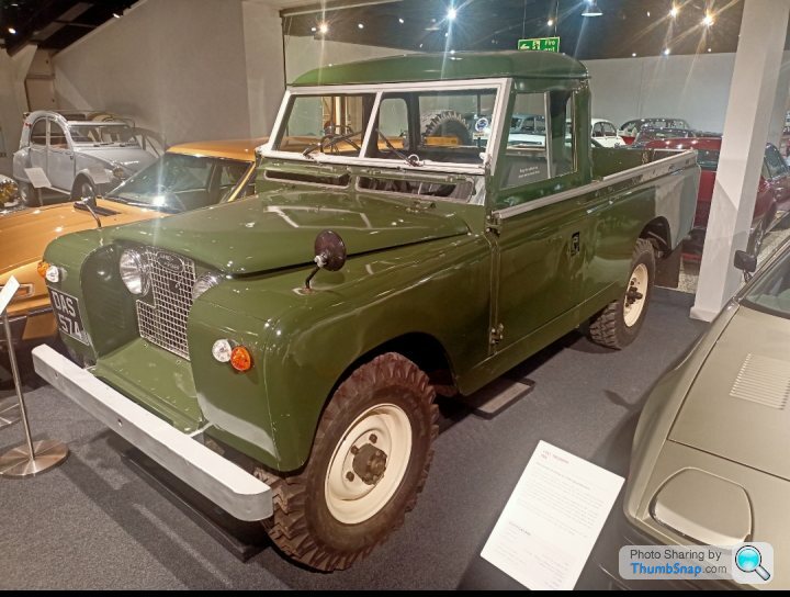
Getting that radius at the top of the panels especially on the front wing could be a challenge. Originally I wasn't going to bother and just have flat laser panels but after seeing the real thing it would look a lot nicer. I can always extend out the year it's ready, right?
This is the panel and area that will be most difficult. It probably isn't difficult if you are a fabby, but as we know I'm not!
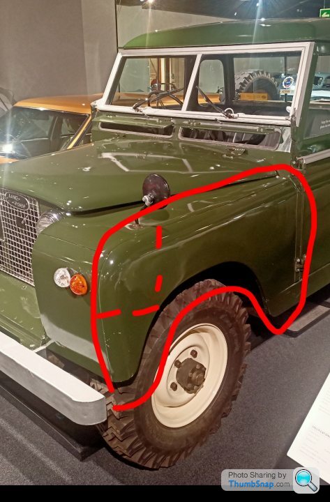
In the dashed area I am thinking of making up a 3d printed press tool and seeing what happens. Shrinking the material in this area is probably going to be a challenge, so I'll suck it and see. Then once I've made a mess give it to one of the fabbies at work!
I need to make up a bench mounted folder so that I can clamp some tube to that to bend the metal around it. Being a parent to two younguns mean you start scribbling down silly ideas whenever you have a spare minute or else they get lost in brain mush, this happened to be in the bath after a long day with them both, so probably lots of errors. They are just ideas so go gently!
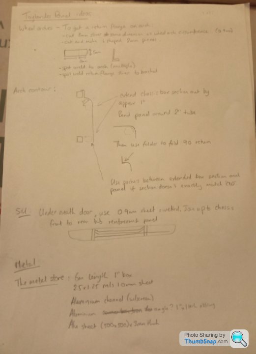
So I think I'll try and mock some parts up, make the metal folder and then order some metal parts. The aluminium on the list is to do the channel on the top of the rear tub and to make the w/screen. I'll try and find some acrylic that will slot in the channel. The 3mm might become 5mm to make the windscreen brackets.
So in summary;
Hand make all panels rather than laser them, because why make life easy!
I took the oldest to Haynes motor museum over the holiday and they had a series 3 there which I took a few photos of as a bit of a guide. The good thing with a series 3 is that the rear tub is higher than the front wings! So I'm now aiming for that as it matches more closely what I have done so far. Sorry landrover lovers!
Getting that radius at the top of the panels especially on the front wing could be a challenge. Originally I wasn't going to bother and just have flat laser panels but after seeing the real thing it would look a lot nicer. I can always extend out the year it's ready, right?
This is the panel and area that will be most difficult. It probably isn't difficult if you are a fabby, but as we know I'm not!
In the dashed area I am thinking of making up a 3d printed press tool and seeing what happens. Shrinking the material in this area is probably going to be a challenge, so I'll suck it and see. Then once I've made a mess give it to one of the fabbies at work!
I need to make up a bench mounted folder so that I can clamp some tube to that to bend the metal around it. Being a parent to two younguns mean you start scribbling down silly ideas whenever you have a spare minute or else they get lost in brain mush, this happened to be in the bath after a long day with them both, so probably lots of errors. They are just ideas so go gently!
So I think I'll try and mock some parts up, make the metal folder and then order some metal parts. The aluminium on the list is to do the channel on the top of the rear tub and to make the w/screen. I'll try and find some acrylic that will slot in the channel. The 3mm might become 5mm to make the windscreen brackets.
So in summary;
Hand make all panels rather than laser them, because why make life easy!
I feel like an insane person talking to myself, but anyhow, its a good log of my mental breakdown.
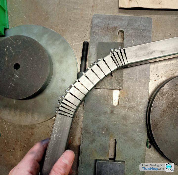
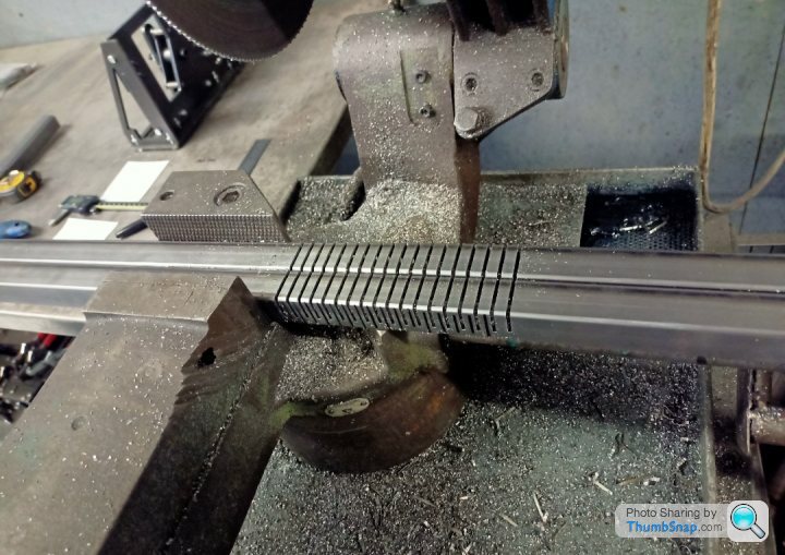
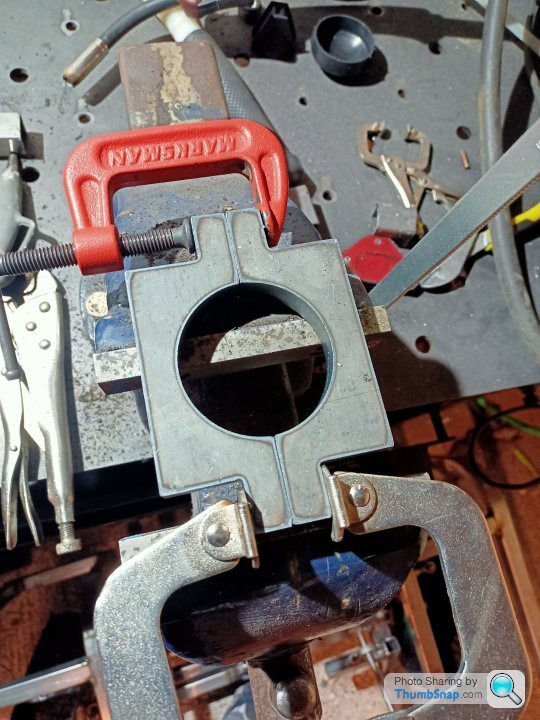
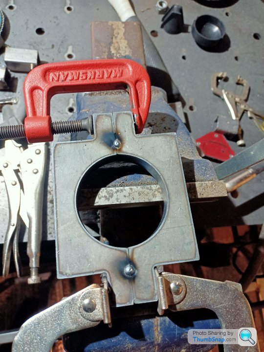
To the rear arch contour and how to form it, 5 minutes with a pen and paper;
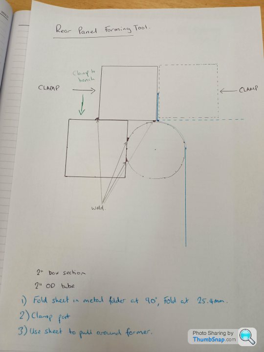
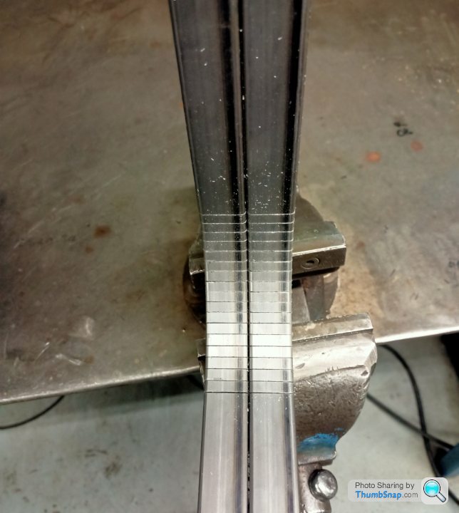
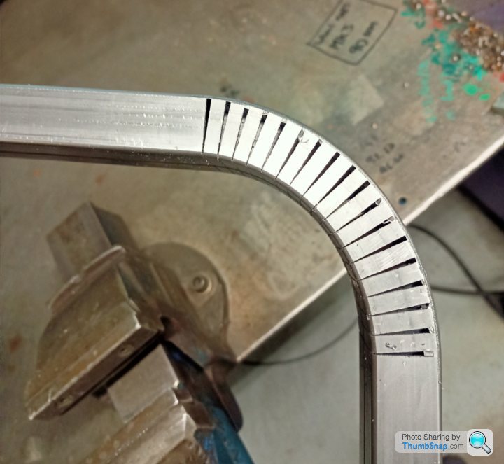
Test piece made up. I made two attempts, with a bit of heat on the bend radius it forms very well although naturally the real panel will be a lot wider so may not form as well:
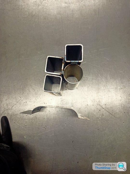
If anyone has detective eyes, they will notice that is 40mm box and 45mm tube which is why it looks a bit odd. I later found some 50box and tube and the results were better with no heat needed. Across the full panel I think a bit of heat will be required to encourage it without the need for smashing it with a hammer.
The front arch with the compound curve is definitely going to be more difficult to make the tool but I have a fall back plan for that when plan A doesn't go very well.
To the rear arch contour and how to form it, 5 minutes with a pen and paper;
Test piece made up. I made two attempts, with a bit of heat on the bend radius it forms very well although naturally the real panel will be a lot wider so may not form as well:
If anyone has detective eyes, they will notice that is 40mm box and 45mm tube which is why it looks a bit odd. I later found some 50box and tube and the results were better with no heat needed. Across the full panel I think a bit of heat will be required to encourage it without the need for smashing it with a hammer.
The front arch with the compound curve is definitely going to be more difficult to make the tool but I have a fall back plan for that when plan A doesn't go very well.
Thanks guys, I'm glad you are reading it and it's made me conscious that I should contribute to the threads on here that I get enjoyment out of but don't comment. Ref doing it out of MDF, 100% it would have been easier. Not only is the material easier to work with but you are working to a well developed plan. I've lost count of the foul ups made so far, and there are lots to come I am sure.
I mainly did it as a challenge to myself that the kids will then benefit from. When it's done hopefully i'll be proud of it whilst watching the kids get enjoyment out of it too. I didn't have the skills, and still don't have the skills but it is continuing to be a good challenge.
The scope is continuing to evolve and make it more and more challenging the more I do. It is stretching me but I think I need a challenge in life or else I tend to get bored.
As nothing is defined, written down, planned I normally come up with a few poor ideas and canvass opinion from colleagues at work or or here. I'm sure it is what Boris does, leak some stupid statements or ideas to the public and then completely change his strategy when everyone disagrees with him.
Panel work:
Now I feel confident that I can make the radius on the rear panel, I'm going to try and hammer a return on the wheel arch cut out. As I am going to make the panels by hand I need a good cutting strategy for the metalwork so that I don't have a lot of dressing work with a grinder.
At the moment I am thinking either buying an air nibbler or using a jigsaw. I will probably make a wooden guide to follow and it would be nice if I could use that wooden guide to hammer the return on the wheel arch as well but I think I might need two guides. I need to get the tool first and work out what the cutting guide might look like. My fall back plan is to do a 1-1 drawing in cad, print it on a plotter at work and then cut it out using that.
Front panels, ideally I want a return on the wings and bonnet/front panels. This is definitely going to be a challenge with lots of shrinking and stretching of material to be done. As with most of this project, I have never done any of that before either! The returns on the inside wing to front bonnet panel won't really show but it would look right if I make them that way rather than having two raw edges of material butted up to each other. So for these I can probably make some slivers in the material and either weld them back up or leave them as they won't be visible.
Steering Wheel:
As mentioned before it is 3d printed and therefore weak between the spokes and the rim/boss. Rather than remake a hybrid metal/printed one I have some carbon fibre sheet that I got a while back to understand the material. So I will try and skin the steering wheel with real carbon to add some strength. I suspect I'll make a bit of a hash of it, so it'll probably be sanded down and painted over to cover the nasties. It would probably look a bit odd if I left the raw carbon in a 60/70's land rover model. On that subject, I'm an idiot, it is a series 2 that I saw in the museum, so that's what I am aiming to make...
Gassing Station | Scale Models | Top of Page | What's New | My Stuff