Ultima Fuel Delivery System Flaw?
Discussion


Hello all,
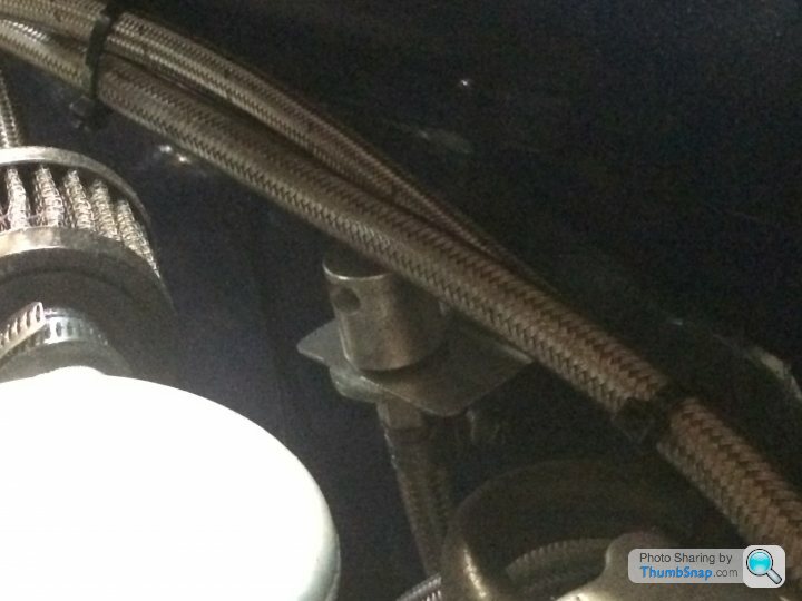
After 2 years of driving the GTR the biggest beef I have with it is the fuel delivery system. I was having intermittent starvation problems that led to what I thought was a faulty fuel switch. (LS7 A/S engine) Finally the left side would no longer empty at all. I ordered a new fuel switch from Ultima and was dreading swapping it as it is a bugger to get to after the engine is installed. It took about two and a half hours to remove the fuel switch box and get it out of the car. The tricky part was emptying the full L/H tank as it would not switch over. I opted to have 2 5 gallon gas cans at the ready and pulled one of the lower tank lines free of the switch and gravity bled the tank. Much to my surprise out of the line was several inches worth of the bladder material from inside the tank. (looks like a Brillo pad) As I dissembled the R/H lines it also had baffle material partially obstructing the supply line. It was obvious why the switch had failed and the fuel starvation was occurring. I feel this design is way too complicated and have been thinking about a simpler option that would have the filters placed before any critical components and not after. I am not a fuel expert so please feel free to chime in with thoughts or similar experience. I have attached my design idea that could be used to run both pumps at once or as Ultima has it one or the other. Any thoughts on the design would be greatly appreciated as I plan to do it next week some time. Pix also attached of the clogged fuel switch.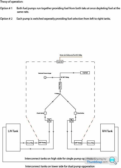
After 2 years of driving the GTR the biggest beef I have with it is the fuel delivery system. I was having intermittent starvation problems that led to what I thought was a faulty fuel switch. (LS7 A/S engine) Finally the left side would no longer empty at all. I ordered a new fuel switch from Ultima and was dreading swapping it as it is a bugger to get to after the engine is installed. It took about two and a half hours to remove the fuel switch box and get it out of the car. The tricky part was emptying the full L/H tank as it would not switch over. I opted to have 2 5 gallon gas cans at the ready and pulled one of the lower tank lines free of the switch and gravity bled the tank. Much to my surprise out of the line was several inches worth of the bladder material from inside the tank. (looks like a Brillo pad) As I dissembled the R/H lines it also had baffle material partially obstructing the supply line. It was obvious why the switch had failed and the fuel starvation was occurring. I feel this design is way too complicated and have been thinking about a simpler option that would have the filters placed before any critical components and not after. I am not a fuel expert so please feel free to chime in with thoughts or similar experience. I have attached my design idea that could be used to run both pumps at once or as Ultima has it one or the other. Any thoughts on the design would be greatly appreciated as I plan to do it next week some time. Pix also attached of the clogged fuel switch.
 |http://thumbsnap.com/KdOsoxdi
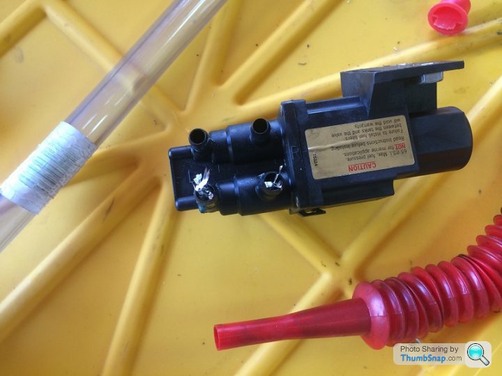 |http://thumbsnap.com/POfyO40u
Spatz,
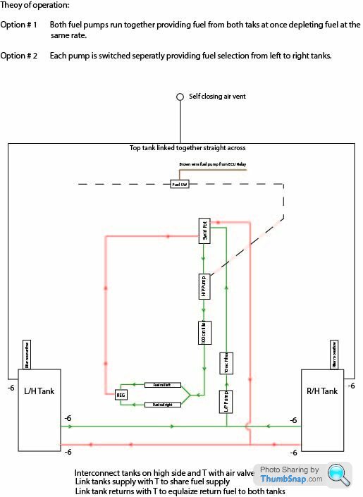
Thanks for the diagrams. In the lower one did you seal off both over flows essentially creating a non vented system. Then you added a T on the top side tank with a self closing fuel switch thus venting the system at this point. What type of switch is available to sense fuel and disable the fuel pumps in the event of a roll over? The fuel rail supplied from AS has one -6 fitting and a Schroeder valve at the rear. Would I have to source another fuel rail as well then? It looks like you would want both to be -6 fittings? Thanks again for the post!
Thanks for the diagrams. In the lower one did you seal off both over flows essentially creating a non vented system. Then you added a T on the top side tank with a self closing fuel switch thus venting the system at this point. What type of switch is available to sense fuel and disable the fuel pumps in the event of a roll over? The fuel rail supplied from AS has one -6 fitting and a Schroeder valve at the rear. Would I have to source another fuel rail as well then? It looks like you would want both to be -6 fittings? Thanks again for the post!
Great Post Max,
I wish I had the insight to have larger top links installed during the tank construction. If I had to do it again there are many things I would change. Wondering if I linked one lower set of -6 together and link 2nd lower set with an offset T closer to the tank I want to draw from would work. This would almost be the same as a -12 interconnect at the bottom of the tank. Fuel would not slosh as it would have to go through two smaller lines? Other option would be to lose the fuel sender in the tank being drawn from and insert a submersible fuel pump as suggested above. This would leave the the 2 lower -6 links uninterrupted. Thoughts anyone?
I wish I had the insight to have larger top links installed during the tank construction. If I had to do it again there are many things I would change. Wondering if I linked one lower set of -6 together and link 2nd lower set with an offset T closer to the tank I want to draw from would work. This would almost be the same as a -12 interconnect at the bottom of the tank. Fuel would not slosh as it would have to go through two smaller lines? Other option would be to lose the fuel sender in the tank being drawn from and insert a submersible fuel pump as suggested above. This would leave the the 2 lower -6 links uninterrupted. Thoughts anyone?
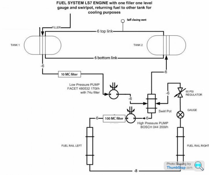
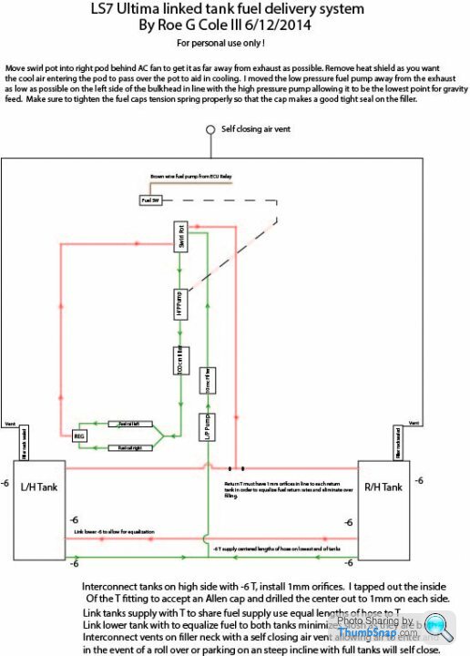
Thanks to all that have posted. I am using Spatz's design keeping both filling ports for now as I have -6 all around. Parts have been ordered and I will re post how the system works after it has been finished. I am moving the swirl pot away from the exhaust where the factory had me place it and moving it on top of the RH tank next to the AC cooler. It will be more accessible there and will be in a much cooler part of the engine bay. Thinking of not re wrapping it with heat shield as I want any heat to dissipate as fuel passes through the pot?? Thoughts anyone.
I have heat shielded both tanks as this will help cut down on exhaust headers being so close to the tanks. A cooler would be a good idea I would just get concerned over time that a leak could develop in the cooler and spell disaster. Anyone try a fuel chiller yet? I think this would be connected right after or before the hi pressure pump.
Thinking more along the lines of adapting this unit. Would swap the tstat to a lower value to activate the fan. IT is intended for oil cooling but pressure tested to 200 psi. Any thoughts?
http://www.ebay.com/itm/B-M-HI-TEK-ENGINE-OIL-AMP-...
http://www.ebay.com/itm/B-M-HI-TEK-ENGINE-OIL-AMP-...
Does anyone know if there is some type of valve that exists that will be normally open but close when air is introduced? Example left and right tanks linked, fuel level low in a hard corner it would be possible for the fuel from the tank being drawn from for it to loose pressure. Idea being draw from link center of both tanks with some sort of valve that would close if air is detected allowing for the tank with fuel to supply the pump?
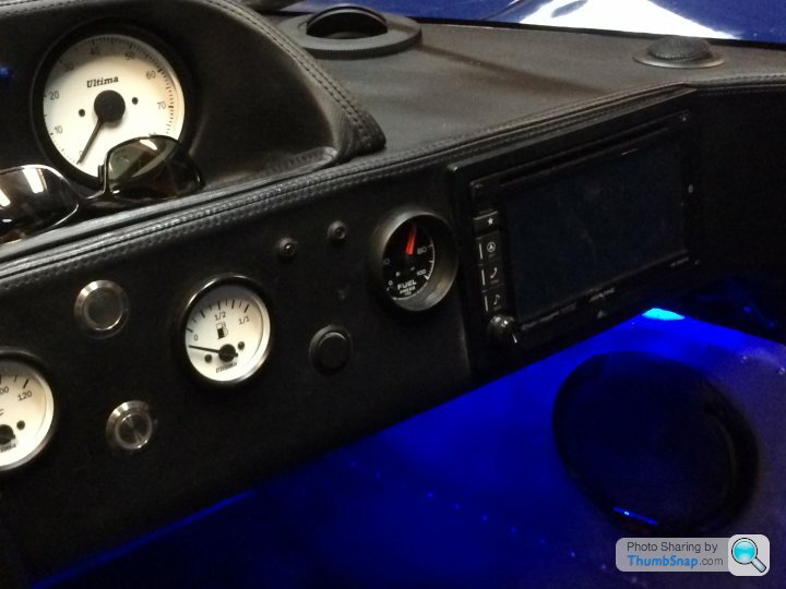
Ok so I have spent the entire weekend replacing the factory fuel system with an all new updated linked tank system. I followed Spatz direction on his system for his updated LS7 engine and basically recreated it. I however ran into an issue, as my tanks are all -6 fittings the return fuel will not equalize fast enough and will fill the return tank to the top of the filler neck before it creates enough pressure to force the fuel to the opposite tank. Version 3 per PDF below. The system otherwise functions fine. I am now thinking the only way to do this with all -6 fittings is to link both supply and return lines with a T to allow the tanks to equalize themselves. Any thoughts on version 4? Trying to keep this system as simple as possible. I did add an Autometer in dash fuel pressure gauge and it read a steady 60 psi at idle and increased slightly with vacuum under power. I highly recommend everyone to add a fuel pressure gauge in the cockpit to allow monitoring of fuel pressure as well as fuel filter condition. The sensor replaced the gauge on the reg and was easily retrofit. After the system is 100% I plan on removing it to document all hose lengths and fittings as well as create a prats list with pix for anyone else looking to do the same. I will also be heat wrapping all fuel lines before they are re installed for the final time. 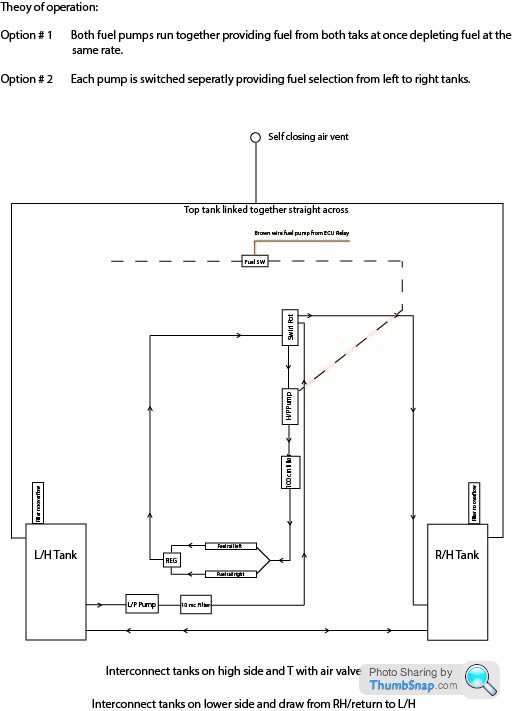

Thanks Max,
That makes sense. So as I am returning to only one tank via top of swirl pot I will need a 1.5 mm restrictor where I attach the return line to the lower tank port. This will allow the tanks to self level via gravity through the lower cross link as I had hoped. I assume the LP pump is made to shut off by itself if it is over the pressure limit of the pump? If the low pressure pump exceeds the allowable restriction? I have been looking for a restrictor to put in line but have not come across one yet. Suppose I could make one with a smaller an coupling?
That makes sense. So as I am returning to only one tank via top of swirl pot I will need a 1.5 mm restrictor where I attach the return line to the lower tank port. This will allow the tanks to self level via gravity through the lower cross link as I had hoped. I assume the LP pump is made to shut off by itself if it is over the pressure limit of the pump? If the low pressure pump exceeds the allowable restriction? I have been looking for a restrictor to put in line but have not come across one yet. Suppose I could make one with a smaller an coupling?
Ok current set up links the top -6 with a T to a self closing air vent. This would need to stay in order to let air into the tanks as they drain correct? Link both lower -6 lines and feed from a T in one of them to low pressure pump. Restrictors at inlet of each top tank to equalize return fuel between tanks. Sound correct?
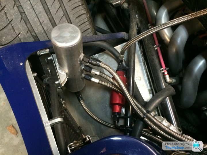
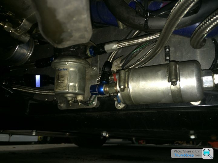
I have experimented with a few ideas and finally came up with a very good solution for the linked tanks. I wanted to test it for several weeks to be sure it was bullet proof. I moved the low pressure pump away from the exhaust and placed it next to the high pressure pump as low as possible to allow the tanks to gravity feed into it. I used 2 equal lengths of fuel line T in to the LP pump to allow near exact draw from each tank. The 2nd set of lower lines became the link to allow for added equalization. As the factory fittings are all -6 this also minimizes sloshing. you effectively create a -12 link at the bottom as you have interconnected both pairs of - 6 fittings. It is important to install orifices in the return T as mentioned by someone prior in this post. I tried it with out however this will cause overfilling to on or the other tanks as the fuel will seek the path of least resistance. I interconnected the filler neck overflows to create vents, using a T and a self closing air valve will allow air to enter the system but will close if fuel is present effectively venting the system. This was mounted up high on the bulkhead. The swirl pot was removed from its location right next to the headers and relocated into the RH side pod behind the AC condenser fan. There was plenty of room there for it and fabricating a bracket was very simple. I removed the heat shield from it as it is far away from the header and you really want the cool air to remove as much heat from the aluminum pot as possible. I also removed the AS fuel rail and installed a larger billet FAST fuel rail. You simply remove the injector spacers and it bolts right on. The LS7 cover will work if you add 3/4" rods to the top of the FAST rails as well! Fuel is fed via the HP pump in to both larger fuel rails at the same time as it is now T at the rear of the fuel rails, the fuel then exists the fuel rails and enters the left and right port of the fuel regulator (this is actually how the regulator should be installed for the LS7 engine) and the return port is T into the top tank link with 1mm orifices. I also installed quick disconnect fittings on the left and right side of the coarse filter on the bulkhead so there is no need to drain the tanks to change the filter element. The fine filter was relocated into the RH side pod and is in line just before the fuel rails. I also added a fuel pressure gauge in the cockpit to monitor pressure. If pressure starts to fall its time to clean or replace the filter elements. 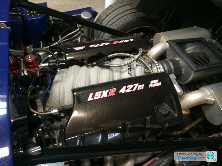
deadscoob said:
I'd say its worth putting some heat shield by your headers, the nimbus stuff works well
Yes I have heat shield on both tanks as the headers are just a few inches from them. The factory doesn't mention this in the manual but many other builders and common sense would tell you to do this. I have purchased a 50 foot roll of reflective hose insulation to sleeve all the fuel lines. This winter I will unhook them and document the length and fitting, install the shield and post it here for anyone who may be interested.Gassing Station | Ultima | Top of Page | What's New | My Stuff