Heating system wiring - can anyone help?
Discussion


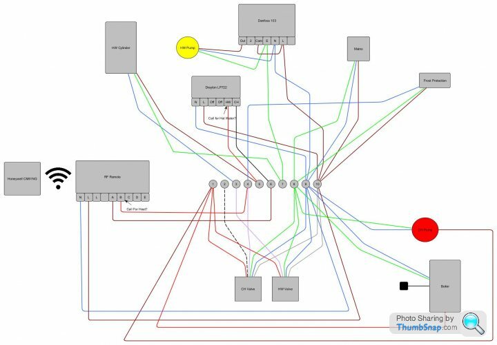
I have an oil fired boiler (Worcester Danesmore 26/32) that runs the heating and hot water for the house. The hot water is stored in a jacketed cylinder (Megaflow Heatrae Sadia). Both are in the garage. The heating is controlled off a wireless remote thermostat in the house, with an RF control box in the garage receiving the signal - whilst the hot water appears to be controlled off one of two timers in the garage - no idea why there are two, it was like that when we bought the house - one is digital and appears to be able to control the HW and CH, whilst the second is a manual 'dial' type timer and appears to control the HW pump. All of this along with the wires for the pumps, valves and boiler all feed into a rather large junction box.
I recently bought a Nest generation 3 smart thermostat and heat link to try and control the system a little better and give us remote access
I have booked two different heating companies over the past couple of months to fit this and service the boiler - both of whom have let me down on the day they were supposed to come out, wasting two days holiday in the process.
Looking at the Nest instructions - the wiring to the heat link appears to be relatively simple and I thought it may be something I could tackle.
The heat link needs power (obviously) and two feeds each for the HW and CH ("call for" and "common") - with a third optional feed for each "satisfied".
I have traced all of the wiring and think I have identified the "call for" feeds, but i'm unsure where the "common" or "satisfied" feels are owing to the complexity of the setup.
I'd appreciate any advice.
Actually - I just found this thread and it appears to have some good suggestions.
http://www.pistonheads.com/gassing/topic.asp?h=0&a...
http://www.pistonheads.com/gassing/topic.asp?h=0&a...
Thanks for the feedback. To understand what you mean about the CH pump. If the HW valve sends power to terminal 1 because the HW has been activated it will also activate the CH pump - but the CH valve is still closed. Is this correct.
I figured out what the danfoss does though. Essentially it switches the hot water pump into recirculation mode to allow instant hot water in the house. The reason it is there is because the boiler and cylinder is in the garage, running it in recirc mode all the time would be too expensive due to the heat losses over the large distance from the garage to the house. It allows the system to recirculate during two time periods in the day - but then just store hot water for the rest of the time.
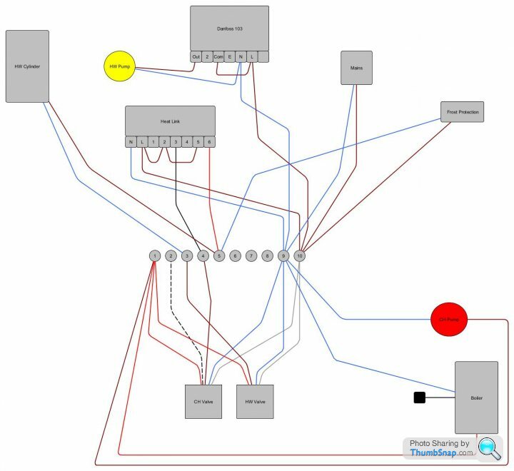
I reckon with the nest installed the wiring should now look like this (I have removed the earth wiring from the diagram for clarity). I'll also need to move the CH pump to terminal 4 based on your feedback.
For clarity, Pin 3 of the heat link is call for heating - pin 6 is the call for hot water.
I figured out what the danfoss does though. Essentially it switches the hot water pump into recirculation mode to allow instant hot water in the house. The reason it is there is because the boiler and cylinder is in the garage, running it in recirc mode all the time would be too expensive due to the heat losses over the large distance from the garage to the house. It allows the system to recirculate during two time periods in the day - but then just store hot water for the rest of the time.
I reckon with the nest installed the wiring should now look like this (I have removed the earth wiring from the diagram for clarity). I'll also need to move the CH pump to terminal 4 based on your feedback.
For clarity, Pin 3 of the heat link is call for heating - pin 6 is the call for hot water.
Edited by Moonhawk on Wednesday 26th October 10:28
I think there is an error above too - for some reason I have moved the frost protection stat to terminal 5 - this should have remained on terminal 4. It's supposed to activate the heating system in the event of a cold snap.
Also - how would I utilise the "satisfied" inputs on the heatlink (pins 1 and 4)? The manual does state these are optional - but if I can utilise them, I might as well.
Also - how would I utilise the "satisfied" inputs on the heatlink (pins 1 and 4)? The manual does state these are optional - but if I can utilise them, I might as well.
Edited by Moonhawk on Wednesday 26th October 11:17
eliot said:
I'm guessing you would run a wire from terminal 1 of the big wiring block to pins 1 & 4, which would indicate when the boiler is actually running.
Yes - I was kinda thinking along those lines - but wondering if I could get the HW signal independent of the CH. By connecting terminal 1 to pins 1 and 4 on the heat link - the heat link will know that a request has been satisfied - but not which one, since either valve will energise this terminal.
I'm not even sure that separating the CH and HW values on the terminal block would work either. If I put the CH valve on terminal 7, I could take a feed off it - but I would still need to jumper terminal 7 to terminal 1 in order to activate the boiler. If the HW valve energised terminal 1 would this signal pass back to terminal 7 through the jumper cable and energise it - essentially giving the same result as if I had just wired both pins of the heat link into terminal 1.
Edited by Moonhawk on Wednesday 26th October 15:48
eliot said:
You only have one thing that satisfies the demand for heat - which is the boiler.
Ok. I was just thinking that the way the system is set up, the boiler heats water in the tank when instructed to do so via the HW control valve and heats the water in the CH system when the CH valve instructs it to. In both cases the boiler fires up - but the valve configuration in each instance will be different and I was wondering whether the heat link would work better if it knew this.
I guess leaving the 'satisfied' feeds off will simply make the heat link assume that when it calls for heat or hot water - it is always satisfied (which is should be - barring a fault on the system like a stuck valve or if the boiler is in fault mode). Alternatively - feeding off terminal 1 - at least the heat link will know that the boiler itself has fired (or been instructed to do so) - regardless of the reason why.
With the CH pump - when there is a call for HW and this pump starts up via terminal 1, is it in fact circulating water between the boiler and the cylinder - hence why it is connected like that. I'll have to trace down the piping to know for sure.
Edited by Moonhawk on Wednesday 26th October 17:28
Well - success I think.
Heating seems to be being controlled from the nest thermostat - I guess i'll find out if the water is too in the morning when I get a shower (edit - hot water is working too - just tried the boost function on the thermostat).
When it came down to it - it was actually quite a simple install - essentially two wires (barring power). Untangling the old controllers took longer than actually connecting the nest.
The best thing is - I now understand how my heating system works. It's always good to learn something new.
Thanks for your help
Heating seems to be being controlled from the nest thermostat - I guess i'll find out if the water is too in the morning when I get a shower
(edit - hot water is working too - just tried the boost function on the thermostat).When it came down to it - it was actually quite a simple install - essentially two wires (barring power). Untangling the old controllers took longer than actually connecting the nest.
The best thing is - I now understand how my heating system works. It's always good to learn something new.
Thanks for your help
Edited by Moonhawk on Wednesday 26th October 20:39

Wondering about another modification. Currently the HW re-circulation pump is controlled separately by a manual Danfoss timer.
Given that the heating of the HW system is now controlled by the Nest - I was wondering whether I should bypass the Danfoss and allow the Nest to control HW re-circulation too.
That way - whenever the Nest is heating the water, it will recirculate (providing it instantly in the house) - but would shut off re-circulation when the heating is done, allowing whatever hot water remains in the system to stay insulated in the tank. It would also allow me to use the Nest's HW "boost" function to provide instant hot water on demand too and would also ensure that the re-circulation is synchronised properly with the HW heating (currently it may be out of sync owing to the fact that the Danfoss timer is not precise).
I believe this will be a single wire mod - moving the live wire of the HW pump from the "out" pin on the Danfoss to pin 6 on the Heat Link. I don't even have to remove the Danfoss timer - just switch it off. That way I can put things back simply if it doesn't work out.
Edited by Moonhawk on Friday 28th October 16:01
Gassing Station | Homes, Gardens and DIY | Top of Page | What's New | My Stuff