Pingu's Next Project - A Flowbench
Discussion


I make (and reject) a lot of modifications, especially engine modifications.
I test my engine modifications with a manometer before I try them on the car, then I test them on the car with a datalogger.
The manometer I use simply measures the pressure drop across the OEM part and the pressure drop across the modified part. It works fairly well, but I am aware that the inlet pressure is not consistent in the tests, even though I am using the same air pump (either a vacuum cleaner, or a leaf blower).
So, I've decided to build a proper flowbench based on the Wikipedia description ( https://en.wikipedia.org/wiki/Air_flow_bench)
The pump will be my stripped-down vacuum cleaner.
Does anyone know anything about minimum plenum sizes, or anything else that I might need to know?
I've just measured the vacuum cleaner at 318 cfm (60mm orifice, 54.6 m/sec)
Mr Vizard was a hero of mine when I was at college in the late 80s. It's great to see that he seems to be as generous with his knowledge as I hoped when I was a yoof.
I've never heard of "floating pressure drop", so I'll give it a Google. - TAVM.
I read the link last night and the "Low Budget Flow Bench" looks like what I have already.
I am looking at the intake system (upto, but not including the plenum) - the intake tube, the air filter box, the air filter and the MAF.
I may also look at cylinder heads, but that is not very likely, other that to test only. I think that modifying cylinder heads for performance is best left to the experts (like Vizard, not your local engineering shop). There's much more to air flow in a cylinder head than volumetric air flow . Swirl and tumble needs to be properly designed into a system, and your local engineering shop just don't have the mixture of skill and knowledge.
I've never heard of "floating pressure drop", so I'll give it a Google. - TAVM.
I read the link last night and the "Low Budget Flow Bench" looks like what I have already.
I am looking at the intake system (upto, but not including the plenum) - the intake tube, the air filter box, the air filter and the MAF.
I may also look at cylinder heads, but that is not very likely, other that to test only. I think that modifying cylinder heads for performance is best left to the experts (like Vizard, not your local engineering shop). There's much more to air flow in a cylinder head than volumetric air flow
. Swirl and tumble needs to be properly designed into a system, and your local engineering shop just don't have the mixture of skill and knowledge.Interesting images on "floating pressure drop flow bench" on Google. ( https://www.google.co.uk/search?q=floating+pressur...)
Does anyone know the pros and cons of the order for
1. Pump - Test Plenum - Metering Plenum
2. Test Plenum - Pump - Metering Plenum (as on Wikipedia)
3. Test Plenum - Metering Plenum - Pump
I suspect that option 3 is best as that is basically what a vacuum cleaner is designed to do. My initial thought was that it could cause the motor to burn out if the flow is restricted, but if I control the Test Plenum pressure by allowing air to enter the pump AFTER the Metering Plenum - Bingo.
Any thoughts?
It works - in a fashion  .
.
It needs some fettling. I can test items with <300cfm flow rates using a 10mm orifice. I will try to add additional suction devices and will hopefully be able to get some mega-suction.
Time to find some broken cylinder vacuum cleaners with working motors.
I'll post up some video of it later.
.It needs some fettling. I can test items with <300cfm flow rates using a 10mm orifice. I will try to add additional suction devices and will hopefully be able to get some mega-suction.
Time to find some broken cylinder vacuum cleaners with working motors.
I'll post up some video of it later.
Mignon said:
Stuff +
I can explain how the manometer readings can be converted to accurate flow later if you like.
Several things about your set-up that wouldn't suit me, even though I would prefer it.I can explain how the manometer readings can be converted to accurate flow later if you like.
I don't have the space for a permanent set-up.
I don't have any of the materials that you used, so I would have had to buy them. I only spent £10 on the manometer backboard and some 2"x1".
I'd like to see your set-up in action.
What is the largest orifice plate that you can use? I am limited to a 12mm orifice, as my vacuum cleaner can only just get a pressure difference of 27.5" if I use a 13mm orifice.
I need to make some properly machined orifices, as the ones that I have at the moment are just drilled holes in wood
 .
.I'd be really interested in how you calibrate the flow bench. I have an anemometer, and my plan was to use fluid dynamics calculations based on Area and Velocity. The accuracy of each measurement would be poor, so the calculated flow rate would be even worse.
Mignon said:
Christ, you're tight.
Tighter than a penguin's ars....Mignon said:
My bench is a floating pressure drop bench so it is not relevant what pressure drop is actually pulled across the test piece. The flow at a nominal 25" of water is worked out mathematically from the actual pressure drop achieved using the square root law.
I was under the impression that you had to actually pull 28" in order to get a realistic air velocity. As air is compressible, the faster it flows, the more compressed it is. I need to do some more reading.Mignon said:
If made correctly the bench needs no calibration. All parts of the design were done to properly follow the guidelines in British Standard 1042.
More reading to do.Mignon said:
The measuring orifice plate needs to be measured accurately and made properly sharp (square) edged and then it will achieve the expected flow coefficient.
I should be able to do this quite easily on my lathe.Mignon said:
If you are prepared to calibrate your bench against a good known one then you don't need an accurately made orifice plate. Any sort of hole in a sheet of metal will do and you just work out its flow coefficient. You could actually make almost all of it from wood.
This was my fallback optionMignon said:
I see no point in a flow bench that is not accurately calibrated because you can't compare your results with known targets or anyone else's work.
I agree with you, but this is the only reason to calibrate a flow bench. I was only planning on comparing my own test pieces, so a calibrated flow bench is only a "nice to have" at the moment. It may become a "need to have" in the future.Many thanks for your time

Mignon said:
pingu393 said:
I was under the impression that you had to actually pull 28" in order to get a realistic air velocity. As air is compressible, the faster it flows, the more compressed it is. I need to do some more reading.
Definitely not. There just needs to be enough flow so that it's turbulent not laminar and that happens very quickly. A couple of inches of pressure drop is enough which is about what a single vac motor gets to with a big valve at high lift.
What you say makes sense and agrees with my observations with a smoke generator.
Mignon said:
If you are wanting a flowbench to test cylinder head modifications then I suggest you read this thread.
https://www.pistonheads.com/gassing/topic.asp?h=0&...
Excellent read. Made even better by David Vizard's contributions, he is to engines what King Kenny is to football https://www.pistonheads.com/gassing/topic.asp?h=0&...

Also posted in https://www.pistonheads.com/gassing/topic.asp?h=0&...
Hopefully, one of the earlier posters will read this...
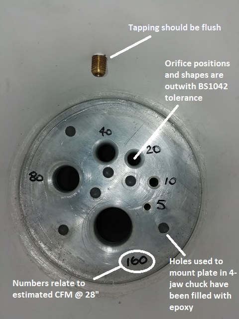
According to Helgesen, the orifice sizes for the following volumetric air flows are...
5CFM --> 0.210"
10CFM --> 0.296"
20CFM --> 0.419"
40CFM --> 0.594"
80CFM --> 0.840"
160CFM --> 1.185"
From the equation, Diameter = SQRT ( ( 4 * Q ) / ( SQRT ( 2 * ( Change in Pressure ) / Density ) ) ) we get...
5CFM --> 0.209"
10CFM --> 0.295"
20CFM --> 0.418"
40CFM --> 0.591"
80CFM --> 0.836"
160CFM --> 1.182"
Can anybody explain why some of the calculated orifice diameters are outside the tolerance values of the Helgesen diameters?
Is it a case of "close is good enough" and just ignore the +/-0.001" tolerance?
Hopefully, one of the earlier posters will read this...
According to Helgesen, the orifice sizes for the following volumetric air flows are...
5CFM --> 0.210"
10CFM --> 0.296"
20CFM --> 0.419"
40CFM --> 0.594"
80CFM --> 0.840"
160CFM --> 1.185"
From the equation, Diameter = SQRT ( ( 4 * Q ) / ( SQRT ( 2 * ( Change in Pressure ) / Density ) ) ) we get...
5CFM --> 0.209"
10CFM --> 0.295"
20CFM --> 0.418"
40CFM --> 0.591"
80CFM --> 0.836"
160CFM --> 1.182"
Can anybody explain why some of the calculated orifice diameters are outside the tolerance values of the Helgesen diameters?
Is it a case of "close is good enough" and just ignore the +/-0.001" tolerance?
Edited by pingu393 on Monday 3rd September 23:41
Thanks very much for that. One of my guesses for the difference was experimentation.
At the moment, I am building a comparative flowbench, but will be aiming to modify (redesign ) it to be able to "measure" CFM.
I prefer your idea of aiming for a target sized orifice and then measuring what you get as accurately as possible.
Quick question about measuring CFM. I haven't seen any way to measure CFM. Is the only way to measure pressure difference, measure orifice diameter and calculate CFM?
The alternative makes my mind boggle (and involves a balloon and a stopwatch )
)
Something that I noticed with my experiments was that some components give the same static result, but the pressure in the manometer changes at a different rate. I used my GoPro at 50fps and counted the frames between two marks on the manometer and found that air must accelerate faster through some components, even though the final reading is the same. Is this something that many people have looked at? After all, an IC engine is not constant flow.
At the moment, I am building a comparative flowbench, but will be aiming to modify (redesign
) it to be able to "measure" CFM.I prefer your idea of aiming for a target sized orifice and then measuring what you get as accurately as possible.
Quick question about measuring CFM. I haven't seen any way to measure CFM. Is the only way to measure pressure difference, measure orifice diameter and calculate CFM?
The alternative makes my mind boggle (and involves a balloon and a stopwatch
)Something that I noticed with my experiments was that some components give the same static result, but the pressure in the manometer changes at a different rate. I used my GoPro at 50fps and counted the frames between two marks on the manometer and found that air must accelerate faster through some components, even though the final reading is the same. Is this something that many people have looked at? After all, an IC engine is not constant flow.
Thanks for the CFM reply. It's always an in-built source of errors using calculations rather than measurement, but hey-ho
Now imagine a different orifice (B) which gives the same pressure drop at constant flow.
When I tested orifice (A), the fluid in the manometer took 2.08 seconds to move between two marks.
When I tested orifice (B), it took 1.54 seconds to move between the two marks.
I would conclude that the orifice (B) is better as air can accelerate through it faster.
Do you know if anybody has studied this, or is a flow bench only useful for measuring steady, constant flow?
Mignon said:
I have no idea about your final point.
I guess the easiest way to explain it would be to imagine an orifice (A) which gives a certain pressure drop at constant flow (after everything has settled down).Now imagine a different orifice (B) which gives the same pressure drop at constant flow.
When I tested orifice (A), the fluid in the manometer took 2.08 seconds to move between two marks.
When I tested orifice (B), it took 1.54 seconds to move between the two marks.
I would conclude that the orifice (B) is better as air can accelerate through it faster.
Do you know if anybody has studied this, or is a flow bench only useful for measuring steady, constant flow?
I ran into this on a certain middle eastern government's website ...
BS 1042 Part 1 Section 1.1
I've already made some serious changes to my flow bench - a complete redesign. Having read the standard, I now have to make some changes to the orifice plate tube (the white tube with the arrow). I should have searched harder for the document when Mignon advised me
Current setup...
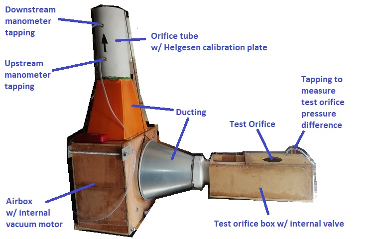
View of Helgesen calibration plate (upstream side visible, downstream side has sharp edges)...
View of internal valve...
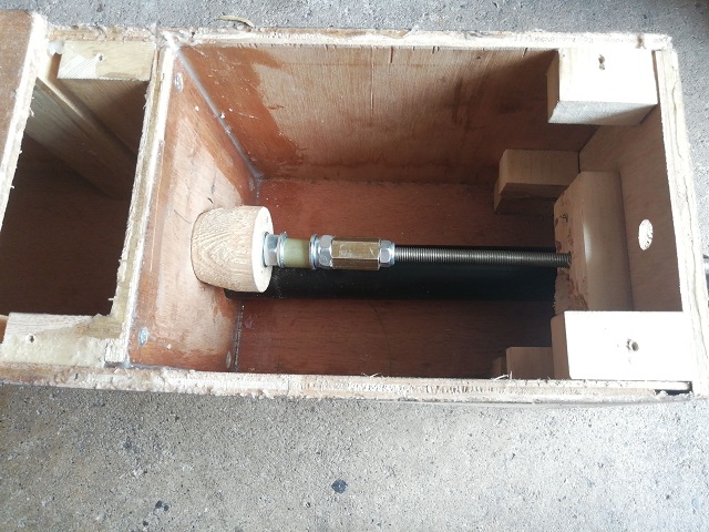
[It's purpose is maintain a known pressure drop (usually 28" H2O) inside the test orifice box.]
Modifications Required
1. The orifice plate(s) need to conform to the dimensions in Method 7 of the standard.
2. The orifice plate tube needs to conform to the dimensions in Method 6 of the standard.
Link to flow bench program thread
...BS 1042 Part 1 Section 1.1
I've already made some serious changes to my flow bench - a complete redesign. Having read the standard, I now have to make some changes to the orifice plate tube (the white tube with the arrow). I should have searched harder for the document when Mignon advised me
Current setup...
View of Helgesen calibration plate (upstream side visible, downstream side has sharp edges)...
View of internal valve...
[It's purpose is maintain a known pressure drop (usually 28" H2O) inside the test orifice box.]
Modifications Required
1. The orifice plate(s) need to conform to the dimensions in Method 7 of the standard.
2. The orifice plate tube needs to conform to the dimensions in Method 6 of the standard.
Link to flow bench program thread
Edited by pingu393 on Friday 19th October 23:22
Edited by pingu393 on Tuesday 6th November 11:12
The following posts are mainly for my benefit and are the algorithms inside the Excel spreadsheet that I use to calculate the volume flow rate.
The standard that I have based the spreadsheet on is ISO 5167
ISO 5167 Spreadsheet
The standard that I have based the spreadsheet on is ISO 5167
ISO 5167 Spreadsheet
[Air Pressure Equations]
Temp in °F = (9*B4/5)+32
[B4 = Temp in °C]
Height in Feet = B5*3.28084
[B5 = height in metres]
Pressure in inches of Hg = B6*0.02953
[B6 = pressure in mBar (measured on a "sea-level" calibrated barometer]
Latitude in radians = B8*PI()/180
[B8 = latitude in degrees]
Temperature in Rankin = B9+459.67
[B9 = temperature in Farenheit]
Latitude-corrected pressure = B11*((-0.002637*COS(2*B12))+(0.000006*(COS(2*B12))^2)-0.00005)
[B11 = pressure in inches of Hg]
[B12 = latitude in Radians]
Temperature-corrected pressure = B11*((B14-28.63)/((1.1123*B14)+10978))
[B11 = pressure in inches of Hg]
[B14 = temperature in Farenheit]
Altitude-corrected pressure = -29.92126*(1-(1/(10^((0.008135*B10)/((B13+(0.00178308*B10)))))))
[B10 = height in feet]
[B13 = temperature in Rankin]
Total corrected pressure in inches of Hg = B15+B16+B17
[B15 = Latitude-corrected pressure]
[B16 = Temperature-corrected pressure]
[B17 = Altitude-corrected pressure]
Actual pressure in mBar = (B11+B19)*33.8637526
[B11 = pressure in inches of Hg]
[B19 = Total corrected pressure in inches of Hg]
[Air Density Calculations]
Ambient Temperature in Kelvin = B3+273.15
[B3 = Ambient temperature in Celcius]
Pv = 100*(B8+B6*(B9+B6*(B10+B6*(B11+B6*(B12+B6*(B13+B6*(B14+B6*(B15+B6*(B16+B6*(B17))))))))))
[Pv = Vapour pressure in mBar]
[B6 = Dew Point Temperature in Celcius]
[B8 = 0.99999683]
[B9 = -0.0090826951]
[B10 = 0.000078736169]
[B11 = -0.00000061117958]
[B12 = 0.0000000043884187]
[B13 = -0.000000000029883885]
[B14 = 2.1874425E-13]
[B15 = -1.7892321E-15]
[B16 = 1.1112018E-17]
[B17 = -3.0994571E-20]
Pd = 100*(B5-B18)
[Pd = Dry pressure in Pascals (or N/sq m)]
[B5 = Corrected ambient pressure in mBar]
[B18 = Pv (Vapour pressure in mBar)]
Air Density in kg/cu m = (B23/(B26*B27))+(B19/(B25*B27))
[B19 = Pv = Vapour pressure in mBar]
[B23 = Pd = Dry pressure in Pascals (or N/sq m)]
[B25 = 461.4964]
[B26 = 287.0531]
[B27 = Ambient temperature in Kelvin]
[Temperature-Adjusted Orifice Dimension Calculations]
Pipe/Bore Diameter = ((C4*10^(-3))*(1+((C24*10^(-6))*(C17-C3))))*1000
[C3 = Temperature at Measuring Station in Celcius]
[C4 = Bore diameter in mm (as measured)]
[C17 = temperature at upstream tapping plane in Celcius]
[C24 = coefficient of thermal expansion in micrometres/metre Kelvin]
Orifice diameter = ((C5*10^(-3))*(1+((C24*10^(-6))*(C17-C3))))*1000
[C3 = Temperature at Measuring Station in Celcius]
[C5 = Orifice diameter in mm (as measured)]
[C17 = temperature at upstream tapping plane in Celcius]
[C24 = coefficient of thermal expansion in micrometres/metre Kelvin]
Distance to Upstream Tapping Plane = ((C8*10^(-3))*(1+((C24*10^(-6))*(C17-C3))))*1000
[C3 = Temperature at Measuring Station in Celcius]
[C8 = Distance from Upstream face of orifice plate to the upstream tap in mm (as measured)]
[C17 = temperature at upstream tapping plane in Celcius]
[C24 = coefficient of thermal expansion in micrometres/metre Kelvin]
Distance to Downstream Tapping Plane = ((C9*10^(-3))*(1+((C24*10^(-6))*(C17-C3))))*1000
[C3 = Temperature at Measuring Station in Celcius]
[C9 = Distance from Upstream face of orifice plate to the downstream tap in mm (as measured)]
[C17 = temperature at upstream tapping plane in Celcius]
[C24 = coefficient of thermal expansion in micrometres/metre Kelvin]
Diameter Ratio (Beta) = I8/I7
[I7 = Temperature-adjusted bore diameter]
[I8 = Temperature-adjusted orifice diameter]
Relative Upstream Tap Ratio (L1) = I9/I7
[I7 = Temperature-adjusted bore diameter]
[I8 = Temperature-adjusted distance to upstream tapping plane]
Relative Downstream Tap Ratio (L2) = I10/I7
[I7 = Temperature-adjusted bore diameter]
[I8 = Temperature-adjusted distance to downstream tapping plane]
Expansion Factor (Epsilon) = 1-((0.351+(0.256*(I11^4)+(0.93*(I11^8))))*(1-(C22/C16)^(1/C26)))
[I11 = Diameter Ratio]
[C16 = upstream pressure]
[C22 = downstream pressure (must be the same units as C16)]
[C26 = isentropic component at upstream tap temperature]
Approach Velocity = (1-(I11^4))^(-0.5)
[I11 = Diameter Ratio]
M2 (this is a constant used in the calculation of the discharge coefficient) = (2*I13)/(1-I11)
[I11 = Diameter Ratio]
[I13 = Relative Downstream Tap Ratio]
[Reynold's Number Calculations]
For the first iteration of
Reynold's Number --> Discharge Coefficient --> Mass Flow Rate
use Reynold's Number = 1000000
For all other iterations...
Reynold's Number = (4*C2)/(PI()*(C3/1000)*C4)
[C2 = Mass flow rate in kg/s]
[C3 = Bore diameter in mm]
[C4 = Dynamic viscosity at upstream temperature in N-s/sq m]
Edited by pingu393 on Saturday 17th November 14:39
[Discharge Coefficient Calculations]
Alpha = (19000*C4/C9)^0.8
[C4 = Diameter Ratio]
[C9 = Reynold's Number]
Discharge Coefficient (C) = B13+B14+B15+B16+B17+B18+B19+B20
[C3 = Bore diameter in mm]
[C4 = Diameter Ratio]
[C9 = Reynold's Number]
[C7 = Upstream Tap Ratio]
[C10 = Alpha]
[C11 = M2] - see "Dimensions and Readings"
[B13 = 0.5961]
[B14 = 0.0261*C4^2]
[B15 = -0.216*C4^8]
[B16 = 0.000521*(1000000/C9)^0.7]
[B17 = (0.0188+0.0063*C10)*(C4^3.5)*((1000000/C9)^0.3)]
[B18 = (0.043+(0.08*EXP(-10*C7))-(0.123*EXP(-7*C7)))*(1-0.11*C10)*((C4^4)/(1-(C4^4)))]
[B19 = -0.031*(C11-0.8*(C11^1.1))*(C4^1.3)]
[B20 = 0.011*(0.75-C4)*(2.8-(C3/25.4))
Gassing Station | Home Mechanics | Top of Page | What's New | My Stuff