Group C replica Mazda 787B
Discussion


Hi guys,
For anyone that is interested, I am putting my mechanical engineering degree to good use and am building my own car from scratch. I've decided on the Mazda 787B to model the bodywork on but all working parts such as chassis, wishbones, uprights, steering etc.. will be of my own design and more suitable for what will hopefully become a road legal car!
After many months of design work the build is now underway. The chassis is very near completion. I will be starting on the front suspension components soon. I will upload some photos of my work when i next get out to my shed with a camera.
I am posting on here for any thoughts/suggestions. My ultimate goal with this project is to produce a car that i may sell to potential customers and my biggest issue at the moment is how far to go with making what is essentially a road going racer, user friendly for the public roads. Are people really bothered about aluminium panel clad interiors, minimal bucket seats, firm suspension etc?
Many thanks,
Rob
Yes ground clearance is an issue that has been with me throughout the design process. I have read almost every book and every piece of literature i can find on suspension design. I have worked through from the basics of ride frequency and bump/rebound travel and have arrived at wheel rates not too dissimilar from those on an ultima. I know i guy with an ultima and he has been a great help in indicating what works and what doesn't!
I designed the suspension geometry with variable ride height in mind, enabling a slight lift to clear large speed bumps and a drop down to even lower ground clearances for track use.
I designed the suspension geometry with variable ride height in mind, enabling a slight lift to clear large speed bumps and a drop down to even lower ground clearances for track use.
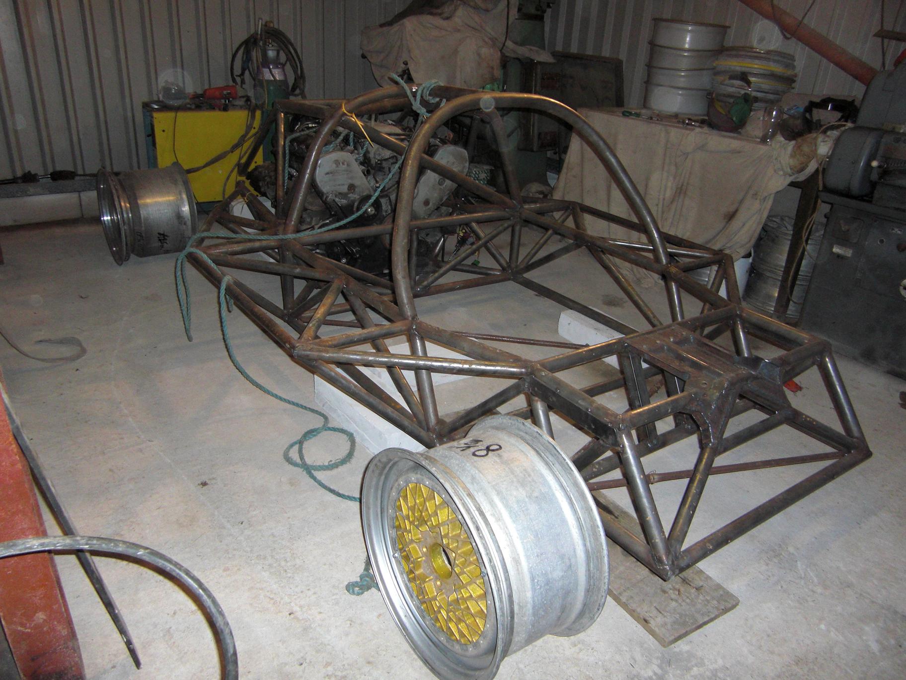
Here's a pic of the spaceframe off the jig and on the floor yesterday 
Thanks for all your help guys, i really appreciate it. I have been employed as a mechanical design engineer for the last 3 years and i now have a fair bit of experience with project design, managemenet, aftersales etc so this will hopefully put me in a good position for this project. As i said i'm really on here to show everyone who's intersted what im up to and to make sure im producing a car that is what people want. As many of you have pointed, the Ultima GTR is probably the best Group C inspired car out there at the moment and is probably the biggest factor in inspiring me to take on this project. Aside from all the research i have done on the group C / GTP cars, i have also spent a great deal of time looking at the ultima for how certain aspects of a race car must be adapted to produce a legal road car. As such, although my car will be modelled visually on the Mazda, obviously there will need to be some tweaking in order to meet rules and regs etc.
I think compared to some kit cars, more of the individual components will be bespoke but i wanted it to be this way so that aspects such the suspension geometry can be exactly as i want them to be. Where i work we design and manufacture low-volume bespoke vehicles, fabricating and machining almost all components. Aside from the manual machine tools i have in my own shed, at work i do have accesss to full cnc machining and turning centres. So although parts may for this first prototype be one-off specials, i will still have the designs and machine programs to produce more sets of parts/spares if i need them.
For those of you with a keen eye, the engine i will be using in this development 'mule' is a 4.2L N/A Audi V8. It is running around 360hp in this current state of tune and i am sure will be ample enough for testing. I picked up the engine fairly cheap along with the transaxle, so i can really test the car when its up and running without worrying to much if either of the two lets go ! The only downside to the audi transaxle is that it is incredibly short from mounting face to output CV joints. To keep the engine forward and maintain weight distribution i will be fitting a bell housing between the transaxle and engine.
I have uploaded more pics at: http://groupcreplica.blogspot.com/
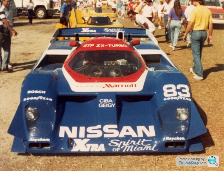
As a side note, the other car i considered modelling my car on is the Nissan GTP ZX-Turbo. I decided against it because of the love or hate it appearance. I personally think it looks ace but i'm sure its not to everyones taste!
Thanks for all your help guys, i really appreciate it. I have been employed as a mechanical design engineer for the last 3 years and i now have a fair bit of experience with project design, managemenet, aftersales etc so this will hopefully put me in a good position for this project. As i said i'm really on here to show everyone who's intersted what im up to and to make sure im producing a car that is what people want. As many of you have pointed, the Ultima GTR is probably the best Group C inspired car out there at the moment and is probably the biggest factor in inspiring me to take on this project. Aside from all the research i have done on the group C / GTP cars, i have also spent a great deal of time looking at the ultima for how certain aspects of a race car must be adapted to produce a legal road car. As such, although my car will be modelled visually on the Mazda, obviously there will need to be some tweaking in order to meet rules and regs etc.
I think compared to some kit cars, more of the individual components will be bespoke but i wanted it to be this way so that aspects such the suspension geometry can be exactly as i want them to be. Where i work we design and manufacture low-volume bespoke vehicles, fabricating and machining almost all components. Aside from the manual machine tools i have in my own shed, at work i do have accesss to full cnc machining and turning centres. So although parts may for this first prototype be one-off specials, i will still have the designs and machine programs to produce more sets of parts/spares if i need them.
For those of you with a keen eye, the engine i will be using in this development 'mule' is a 4.2L N/A Audi V8. It is running around 360hp in this current state of tune and i am sure will be ample enough for testing. I picked up the engine fairly cheap along with the transaxle, so i can really test the car when its up and running without worrying to much if either of the two lets go
! The only downside to the audi transaxle is that it is incredibly short from mounting face to output CV joints. To keep the engine forward and maintain weight distribution i will be fitting a bell housing between the transaxle and engine.I have uploaded more pics at: http://groupcreplica.blogspot.com/
As a side note, the other car i considered modelling my car on is the Nissan GTP ZX-Turbo. I decided against it because of the love or hate it appearance. I personally think it looks ace but i'm sure its not to everyones taste!

Edited by RobBiggs on Friday 1st January 17:53
Hi Everyone,
Sorry for the delay in replying. I have had a very busy beginning to the year. Had to swap my Merc Cosworth for something a little more practical/economical amongst other things. Never seemed to get any better than 25mpg no matter how i drove it! Now driving a Pug 306 TD. Not especially quick but handles nicely.
Ive just been going over some of the posts on this thread..
Pilbeam mp62 - As Paul correctly stated, althought the steering arms in my design to run at an angle, they are the same length as and do run paralell to the upper control arms meaning there will be no bump steer. The basic theory behind setting up a geometry for zero bump steer is that the upper and lower control arms and the steering link all converge and intersect about a common instant centre. I am using this design so that i can adjust static geometry such as camber by adding or removing shims from behind the common mount for the top link and steering link without affecting bump steer at all.
Fuoriserie - Im not sure what exactly you are asking. Im more than happy for you to make some sketches. Im sure everyone would be interested to see your work but do you just want to work from the pictures on my blog or do you need me to send you some more useful ones? Let me know and i'll see what i can do.
n3il123 - Yes the structure over the engine is in places very close to the engine. That section of the spaceframe is however quick and easy to remove for installation, removal and if necessary working on the engine and ancilliaries. Even with this piece removed the spaceframe is more than adequate in terms of torsional and beaming stiffness. I did even contemplate not having it at all but in the end decided the 50% increase in overall stiffness was worth the extra 20-25kg. As i mentioned before, i intend ultimately to install a mazda rotary engine in place of the audi v8 as it seems far more apprpriate seeing as it is a mazda afterall and then space should be far less of an issue.
Browser07 - Yes i think making a more universal underpinnings to the car so that different bodies could be fitted would be a very good idea. Overall height and width are very similar between models although wheelbase i found from my research seems to be very varied. For example, the mazda 787 measures 2640mm and at the other end of the scale we have the Aston AMR1 at 2896mm. There is also the added issue of placement of cooling rads and fans which are sometimes up in the nose of the vehicle or in the side pods or even in the rear engine compartment - see Aston AMR1 again! I think i remember reading somewhere that some of the Porsch 917s had adjustable wheelbases. Any ideas anyone?
Dom9 - thankyou for your interest in my project. I will obviously get in contact when the time comes!
Anyways, back to the project as it stands...
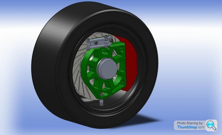
I've been working on designs for the front uprights for the last couple weeks. As for wheel bearings, im going the same route as are F1 teams, BTCC and WRC (i think) where the wheel loads are taken through two large, low profile bearings found in the upright itself. The bearings are spaced apart as wide as is sensibly possible to reduce loadings that result from cornering. In my design, the hub is then a large hollowed-out part that sits inside these bearings, wheel mount flange one end and a split nut and thread to secure it at the other. Once again i have tried not to commit to a specific brake package but at this stage i am working around using the Wilwood W6A caliper and a matching disc that just fits within my 17" wheels. Im happy with my current design but am just doing some calcs and running some final FEA Simulations to check ive not taken too much meat out of the structure in my efforts to keep things lightweight! I should have some more images posted during this week and then i'll be starting manufacture.
Interstingly, if anyone else has had to replace wheel bearings on a more modern car they'll notive how small a unit the sealed pair of bearings is (eg skoda octavia, pug 206...). To me it is no surpise that they can fail, especially when driven hard or the tyres are replaced to improve grip.
Sorry for the delay in replying. I have had a very busy beginning to the year. Had to swap my Merc Cosworth for something a little more practical/economical amongst other things. Never seemed to get any better than 25mpg no matter how i drove it! Now driving a Pug 306 TD. Not especially quick but handles nicely.
Ive just been going over some of the posts on this thread..
Pilbeam mp62 - As Paul correctly stated, althought the steering arms in my design to run at an angle, they are the same length as and do run paralell to the upper control arms meaning there will be no bump steer. The basic theory behind setting up a geometry for zero bump steer is that the upper and lower control arms and the steering link all converge and intersect about a common instant centre. I am using this design so that i can adjust static geometry such as camber by adding or removing shims from behind the common mount for the top link and steering link without affecting bump steer at all.
Fuoriserie - Im not sure what exactly you are asking. Im more than happy for you to make some sketches. Im sure everyone would be interested to see your work but do you just want to work from the pictures on my blog or do you need me to send you some more useful ones? Let me know and i'll see what i can do.
n3il123 - Yes the structure over the engine is in places very close to the engine. That section of the spaceframe is however quick and easy to remove for installation, removal and if necessary working on the engine and ancilliaries. Even with this piece removed the spaceframe is more than adequate in terms of torsional and beaming stiffness. I did even contemplate not having it at all but in the end decided the 50% increase in overall stiffness was worth the extra 20-25kg. As i mentioned before, i intend ultimately to install a mazda rotary engine in place of the audi v8 as it seems far more apprpriate seeing as it is a mazda afterall and then space should be far less of an issue.
Browser07 - Yes i think making a more universal underpinnings to the car so that different bodies could be fitted would be a very good idea. Overall height and width are very similar between models although wheelbase i found from my research seems to be very varied. For example, the mazda 787 measures 2640mm and at the other end of the scale we have the Aston AMR1 at 2896mm. There is also the added issue of placement of cooling rads and fans which are sometimes up in the nose of the vehicle or in the side pods or even in the rear engine compartment - see Aston AMR1 again! I think i remember reading somewhere that some of the Porsch 917s had adjustable wheelbases. Any ideas anyone?
Dom9 - thankyou for your interest in my project. I will obviously get in contact when the time comes!
Anyways, back to the project as it stands...
I've been working on designs for the front uprights for the last couple weeks. As for wheel bearings, im going the same route as are F1 teams, BTCC and WRC (i think) where the wheel loads are taken through two large, low profile bearings found in the upright itself. The bearings are spaced apart as wide as is sensibly possible to reduce loadings that result from cornering. In my design, the hub is then a large hollowed-out part that sits inside these bearings, wheel mount flange one end and a split nut and thread to secure it at the other. Once again i have tried not to commit to a specific brake package but at this stage i am working around using the Wilwood W6A caliper and a matching disc that just fits within my 17" wheels. Im happy with my current design but am just doing some calcs and running some final FEA Simulations to check ive not taken too much meat out of the structure in my efforts to keep things lightweight! I should have some more images posted during this week and then i'll be starting manufacture.
Interstingly, if anyone else has had to replace wheel bearings on a more modern car they'll notive how small a unit the sealed pair of bearings is (eg skoda octavia, pug 206...). To me it is no surpise that they can fail, especially when driven hard or the tyres are replaced to improve grip.
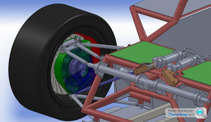
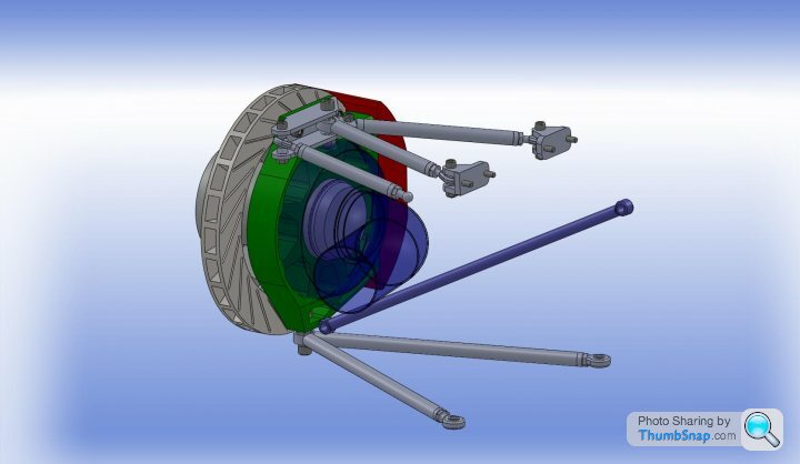
As promised, some pics of my front upright and hub designs:
I am hopijng to source the bearings and materials this week and then start manufacturing!
Chuntington101 - you do have a keen eye! yes that is a 350 chevy i had modelled in that particular view. I do intend to make most common powerplants able to fit in the car (within reason). The Audi v8 is to my knowledge one of the more bulky engines to fit in a tight engine compartment. It may be very short but it is also very wide and quite tall. A chevrolet LS1 powerplant for example is longer but also not as tall or as wide. Obviously rotary engines should not be a problem to fit in there, as well as inline fours and V6s.
The chassis itself will have basic mounts to which engine mounts specific to the engine choice can be bolted. Computer models of even very common engines are so hard to come by, the old chevy model was one I found on the net on some off-road buggy forum i think. It would be interesting to see what else would fit in there if anyone has any overall dimensions pf any popular engines?
AtomicRex - A 3/4 rotor engine would obviously be my engine of choice for a more authentic sound! Have you ever put one together before? When i did a search before all i came up with was some guy the other side of the world in Japan I think. Also, I second Dom9s comment and would be very interested to know if you ever produce any bodies using the 962 moulds!
Edited by RobBiggs on Tuesday 19th January 20:05
The spaceframe is made from a high tensile strength steel, clubman 500 from Elmdon metals. It has superior mechanical properties to mild steel but still retains ductility. This means that in a shunt it will deform and absorb energy in preference to fracture. Bare weight of the chassis is going to be in the region of 120kg. Projected vehicle weight is around 800kgs.
The front roll hoop and connecting brace actually do very little (in relative terms) to stiffen up the structure. The rest of the frame is fully triangulated meaning that no tube is under bending loads, and are instead under direct compression/tension. This is how I achieved good torsional and beaming stiffness values. The front hoop and brace are there more for piece of mind. Thankyou for pointing this out though. I have a feeling the ultima having two may be down to some roll cage specification where the vehicle is used for racing puposes.
Hubs are machined from EN24T high strength steel, upright and associated bracketry machined from 6082 T6 aircraft grade aluminium. The idea with the cooling is that cold air is forced through the holes in the upright, over and around the bearing housing and out through the disc vanes. Im not entirely sure what Mazda did on the 787. I do know many of the cars of the era even had twin calipers clamping on one disc though!
Edited by RobBiggs on Wednesday 20th January 19:35
Dom9 -
Yeah thanks for the heads up on the Mulsanne Corner website. I have visited it many many times before!
Nasty-bob -
I've covered the few points you've made already but basically the car will be modelled on a 787B but may well be tweaked slightly (clearances etc..) in order to meet IVA requirements. Also, the Audi engine is in the car at the mo as a cheap and reliable powerplant (360bhp in standard form) that I will use in testing. Ultimately, a rotary engine is going in.
I am fully aware of the different grades of aluminium. I suppose to say that something is aircraft grade is kind of pointless anyway, seeing as some grades used on an aircraft are not all that special at all. Even so, the mechanical properties of 6082 T6 match if not exceed 6061 T6 which is a known aircraft grade. I was just trying to indicate that I am using a specific engineering alloy with good mechanical properties suitable for a component such as the upright. I have worked carefully using the material suppliers information in carrying out my load, stress and fatigue calculations using industry standard FOS. Thanks for your interest and input though.. Thanks, Rob
For anyone that is interested, this is where I really started my love of designing race-orientated cars : http://www.formulastudent.com/
I was part of the Imperial College London team from 2005 to 2006. It is where a lot of innovative new designs and techniques originate. In 2005 one of the guys on our team produced a set of carbon fibre composite wheels. Even had Ross Brawn jealous as he browsed the pits as they are not allowed to use them in F1!
I was part of the Imperial College London team from 2005 to 2006. It is where a lot of innovative new designs and techniques originate. In 2005 one of the guys on our team produced a set of carbon fibre composite wheels. Even had Ross Brawn jealous as he browsed the pits as they are not allowed to use them in F1!
Edited by RobBiggs on Monday 1st February 19:35
Hi Chris,
My aim at this stage is to put together a car with only the bare essentials necessary to make it run and drive. I will then run this first prototype making any modifications to the design as I go along. I can also get people's feedback on what they would like to see incorprated or changed in order that the second prototype would be almost identical to one that I could sell. So yes my intentions are to make more than one vehicle. Timescales are going to be very dependent on how much interest there is..
Cheers
Rob
Hi everyone. I've been able to get to my shed until this weekend. I have moved jobs and am in the process of moving house so have been rather busy!
In terms of manufacturing, I have just finished the four aluminium alloy top control arm mounts. I now have the material for machining the uprights and am picking up a rotary table for my milling machine tomorrow and then I can begin machining them.
I have been tinkering with the suspension component design for all four corners and have now made the decision to use centrelock wheels. I will still use the BBS rim inners and outers but I will be machining my own 5 spoke wheel centres, similar to these: http://www.fd3s.net/787B/ I have simplified the uprights slightly and managed to lose a bit of weight here and there. I have also started work on the design of the rear suspension


I've always wanted to put the centrelock wheels on the car but to save on time and money I was just going to use the 5 bolt BBS centres I already have. After much thought though, in the interest of authenticity mainly I've decided centrelocks are the way to go. They also look the part too and will make swapping wheels round at the track alot quicker!! It will mean carrying around a large socket and extension bar though.
As a result, I am thinking I may be putting the BBS rim centres and various 16" halves up for sale if there are any takers for the right sort of money??
The body will be made of GRP initially with the view to being made out of Carbon Fibre once the absolute final body design is sorted. I know a guy that can help me with this. There were very few 787b's ever made and tracking them down has been a real task. I should hopefully in the near future be able to get a good look and be able to take photos and measurements etc so along with the blueprints I have I will be able to make my own moulds. As I said before, the body design will have to be tweaked somewhat for a road legal car.
As for tyres, the cars based around using Kumho V70 at all four corners. These tyres are of the road-legal trackday variety...
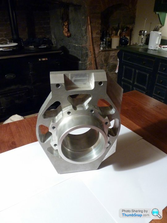
Halfway through machining one half of a front upright at the mo. Awaiting delivery of a larger bore guage for checking the bearing seat as my current ones do not go large enough. Cant see my shed floor for all the aluminium swarf!!
Any chance of some pics of the 962 bodywork AtomicRex??
Any chance of some pics of the 962 bodywork AtomicRex??
No probs at all with you mentioning things. I thinks its good for all on here to express their own views.
Yes the lower control arm upright pivot is in single shear. The geometry I put together mandates having this point as low as possible, very close to the rim itself. I would probably be able to sqeak in another plate thickness at the lower end but the added complication comes when steering the wheel. The control arm tubes themselves will come very close to the drop down plates supporting the second bolt through plate unless they are widely spaced. To cut a long story short I just could not get enough material in there to have any significant improvement in strength. The other option I also considered was using a high angular misalignment bearing mounted with it centreline running fore/aft on the car but once again, when steering the wheel, extra clearance was required either side of the joint to clear the control arm. This then meant the two, now vertical, bolt through sections would have to quite widely spaced placing large bending moment on the bolt.
After much consideration I decided on my current design. I calculated and specced a larger spherical bearing along with the respective fixing bolt at this point so that even if any preload through the joint were released it will still be able to cope with the shear and bending resulting from cornering, braking etc. whilst maintaining a healthy safety factor against yield.
I will be able to adjust castor and also make adjustments to the anti-dive characteristics of the front end which requires me to use the spherical bearing inboard aswell
Target weight 800kg, Rack from Titan motorsport (custom made)
Cheers

B,
There will be twin fuel tanks, one on either side of the car just ahead of the rear wheel side ducts.
I've spent a lot of time working on the spaceframe. I've used numerous programs to model and develop the design, one of them being COSMOSWorks (built into Solidworks), but also: 'Grape', FrameWork' and finally one very laborious hand calculation using the Energy Method. Current torsional stiffness values lie at the 25,000Nm/degree mark although this does not include the affects of the riveted aluminium panelling that will be present in the cockpit. I therefore expect the final values to be higher again.
Many thanks for your pointers and links, it is very difficult to get hold of useful information on other designs. I don't think reversing the triangulations as you mention would affect stiffness and thinking about it, yes it would prob make sense to invert the ones in the horizontal plane so they form more of a bridge shape around the occupants. I have put much consideration into the safety aspects of my design. I could have made the chassis half the weight it is now but I would be worried about it being a little bit too flimsy in the event of a crash! Current weight is around 120-125kg so its still not that heavy though...
I have been debating whether or not to add some gussets to the roll hoops. I see no point in using them anywhere else on my frame since all other tubes meet at nodal points to form a fully triangulated structure. All suspension loads are fed into these nodal points. I.e. all tubes see only compressive/tensile loads and no bending moments. The front roll hoop and connecting tube however are an add-on that cannot realistictly be triangulated and will see large bending moments so I may well be using them here. Are you familiar with their construction? I am assuming they will be similar wall thickness to the tubing, bent over a circular mandrel?
As regards the front suspension, yes the bump steer characteristics are altered when a steering angle is introduced. However, with careful rack positioning fore/aft and by experimenting with different steering lever arm lengths I have manged to reduce this to a minimum. I'm talking about 0.05 degree of toe variation throughout all vertical wheel travel a full lock (around 30 degrees on the inside wheel) reducing down to 0.001 degree of toe variation at a more likely maximum for the track of 10 degrees
I agree I could use your method to adjust castor quite easily but adjusting anti-dive would be more difficult without have a setup that had slots for mounting points making it more difficult to set up. Ultimately I could go the more simplistic route once I've tested and setup the car but for this prototype I'm making most characteristics adjustable so I can play with the handling. I was rightly/wrongly assuming adjustable geometry would be a good thing for someone purchasing atrack-orientated car but maybe a more simplistic route would be better. It all depends what people want??
B, if you don't mind me asking what is your background? You seem like a more 'tech' guy as well as (I assume) being a car nut Do you have any projects of your own?
Cheers
There will be twin fuel tanks, one on either side of the car just ahead of the rear wheel side ducts.
I've spent a lot of time working on the spaceframe. I've used numerous programs to model and develop the design, one of them being COSMOSWorks (built into Solidworks), but also: 'Grape', FrameWork' and finally one very laborious hand calculation using the Energy Method. Current torsional stiffness values lie at the 25,000Nm/degree mark although this does not include the affects of the riveted aluminium panelling that will be present in the cockpit. I therefore expect the final values to be higher again.
Many thanks for your pointers and links, it is very difficult to get hold of useful information on other designs. I don't think reversing the triangulations as you mention would affect stiffness and thinking about it, yes it would prob make sense to invert the ones in the horizontal plane so they form more of a bridge shape around the occupants. I have put much consideration into the safety aspects of my design. I could have made the chassis half the weight it is now but I would be worried about it being a little bit too flimsy in the event of a crash! Current weight is around 120-125kg so its still not that heavy though...
I have been debating whether or not to add some gussets to the roll hoops. I see no point in using them anywhere else on my frame since all other tubes meet at nodal points to form a fully triangulated structure. All suspension loads are fed into these nodal points. I.e. all tubes see only compressive/tensile loads and no bending moments. The front roll hoop and connecting tube however are an add-on that cannot realistictly be triangulated and will see large bending moments so I may well be using them here. Are you familiar with their construction? I am assuming they will be similar wall thickness to the tubing, bent over a circular mandrel?
As regards the front suspension, yes the bump steer characteristics are altered when a steering angle is introduced. However, with careful rack positioning fore/aft and by experimenting with different steering lever arm lengths I have manged to reduce this to a minimum. I'm talking about 0.05 degree of toe variation throughout all vertical wheel travel a full lock (around 30 degrees on the inside wheel) reducing down to 0.001 degree of toe variation at a more likely maximum for the track of 10 degrees
I agree I could use your method to adjust castor quite easily but adjusting anti-dive would be more difficult without have a setup that had slots for mounting points making it more difficult to set up. Ultimately I could go the more simplistic route once I've tested and setup the car but for this prototype I'm making most characteristics adjustable so I can play with the handling. I was rightly/wrongly assuming adjustable geometry would be a good thing for someone purchasing atrack-orientated car but maybe a more simplistic route would be better. It all depends what people want??
B, if you don't mind me asking what is your background? You seem like a more 'tech' guy as well as (I assume) being a car nut
Do you have any projects of your own?Cheers
Good idea for the windscreen. I agree, a curved window profile is most definitely going to be easier and far cheaper to produce than a domed one. I will be making a heat-formed polycarbonate screen for the prototype and then once I am happy with the shape and design I will be getting a mould produced and have a glass one made.
The Ackerman in this setup is minimal. I am of the opinion (as per suspension design reference books) that ackerman becomes less of a reuirement as the car has more cornering potential. It basically comes down to slip angles and the fact that the outside wheel will be taking more of the cornering load and as a result will need fractionally more steering lock compared to the inside wheel.
I've been busy making parts from my aluminium billets these last few weeks and things are coming along. For more pics etc, see my blog http://groupcreplica.blogspot.com/

For the last few days I have been speaking to a CNC machining company local to myself who will now be helping me out. I simply have too much to complete on my own with my manual machines! I will be sending them the drawings for the stub axles and wheel centres in the next couple days so hopefully machining will soon be back on track. What has distracted me the most recently however is the issue of what to do with the bodywork. After much thought, I have decided that with the help of my brother (also an engineer although more artistic than myself ) we will be producing a one-off bodywork that combines many of the attributes and styles of various cars but will now not be a direct copy of anything that exists. I have laid out the basic shapes and features of what will become the final design and I am already quite happy with the results. Any comments please? Bear in mind that the rather purposeful look is intended!


) we will be producing a one-off bodywork that combines many of the attributes and styles of various cars but will now not be a direct copy of anything that exists. I have laid out the basic shapes and features of what will become the final design and I am already quite happy with the results. Any comments please? Bear in mind that the rather purposeful look is intended!Gassing Station | Kit Cars | Top of Page | What's New | My Stuff