Peugeot 205 Saloon Libre - RWD Space-Frame Silhouette Racer
Discussion


I've decided it's about time to drag my arse on to this forum and share my project with everyone.. it's a 205 GTI silhouette racer, designed and built by me to compete in Sports Libre Hillclimbs and thrash on track days. The story so far is pretty long; it's taken me about 3 years so far, from the first concepts to building the "final" design, and is likely to take another year or so from here.
This thread will be exactly how all internet-featured projects should be: open, detailed, and full of pictures! So.. 56k GTFO before your modem implodes. (Sorry, I couldn't resist a dial-up joke) Anyway..
The basic concept is: space frame chassis; SLA suspension with push rod to damper; front engine - rear drive with 2.0 Duratec turbo, Drenth sequential gearbox, Ford 7" diff and all custom shafts; carbon bodywork with front & rear "clamshells", CFD developed aero (as if an 80's brick could be aerodynamic..) with an emphasis on light weight at all times - predicted weight is 600kg with driver, and power output is to be in the region of 350bhp.
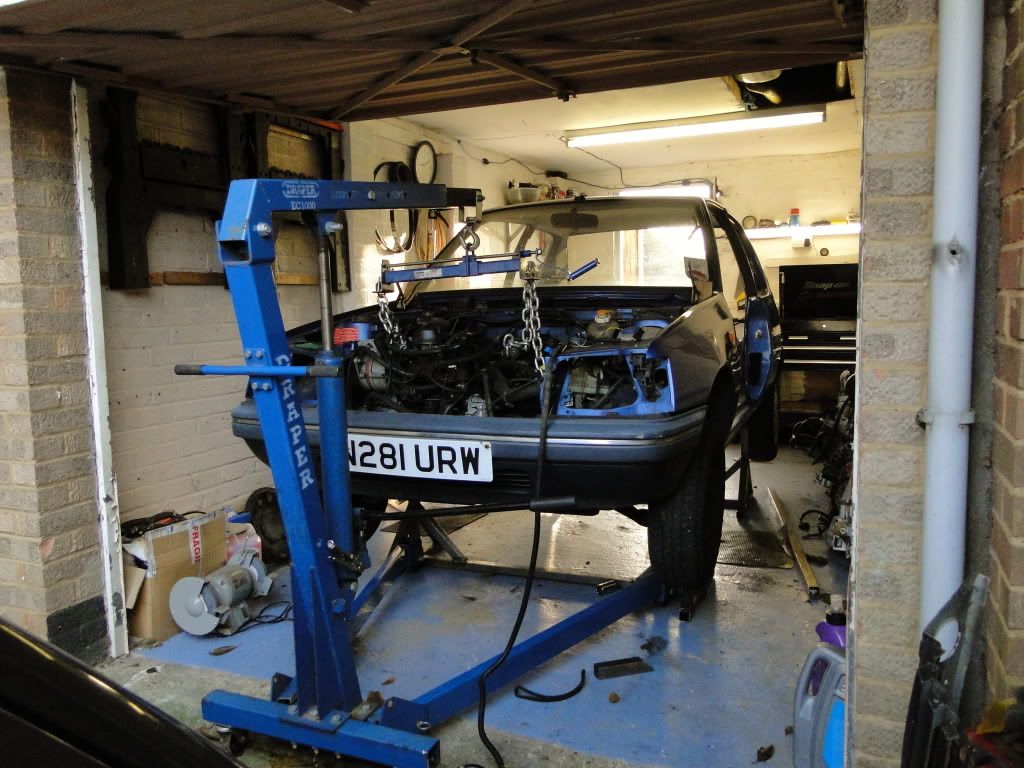
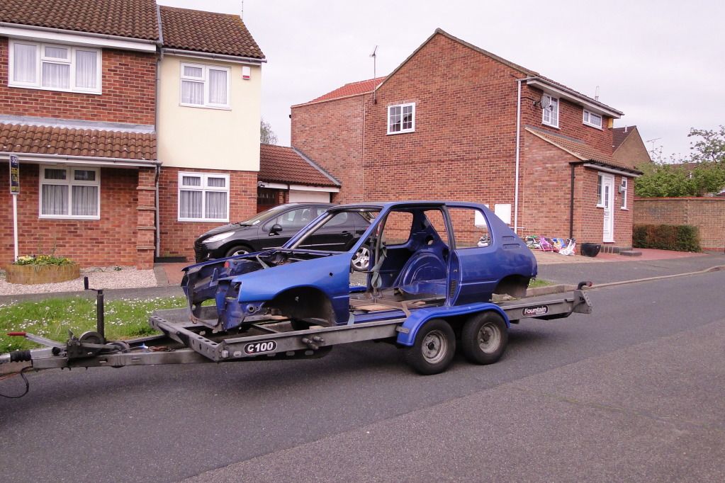
It started with a year of solid design work, then about this time 2 years ago I went out and bought a 1.6 Auto base model to use as the "donor".

It wouldn't stay like that for long, and was raised up on some home-made adjustable stands and duly torn to pieces.
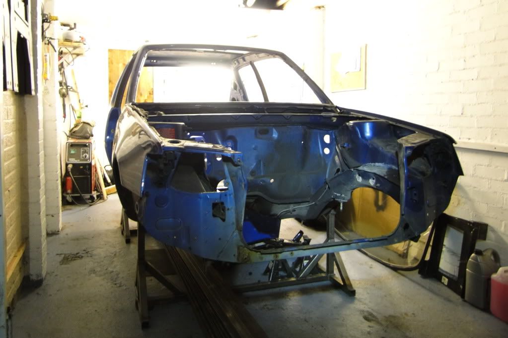
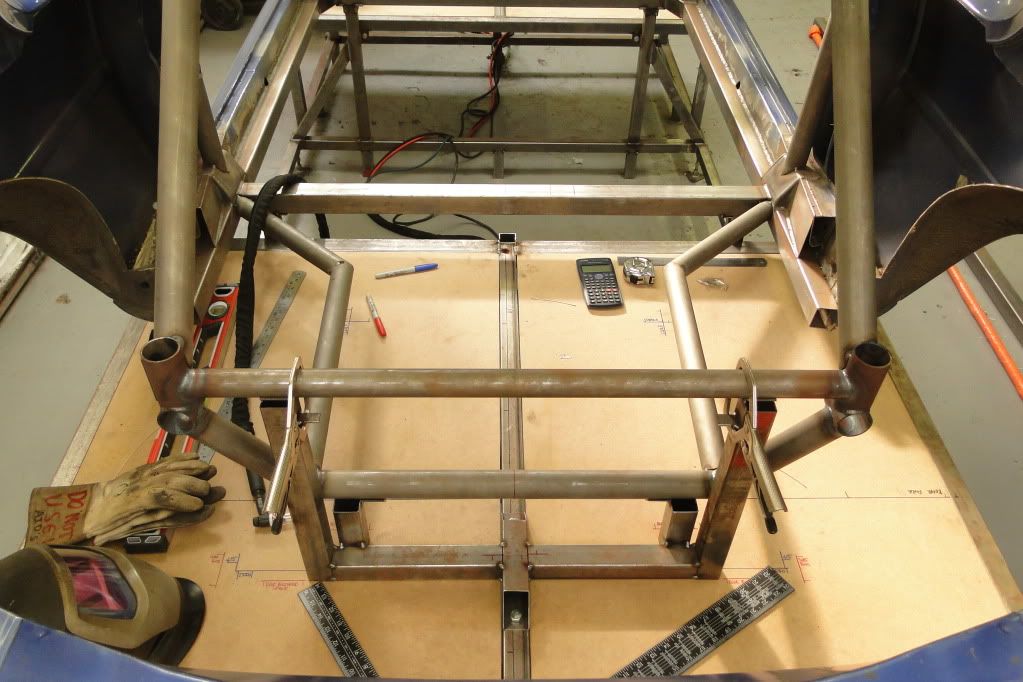
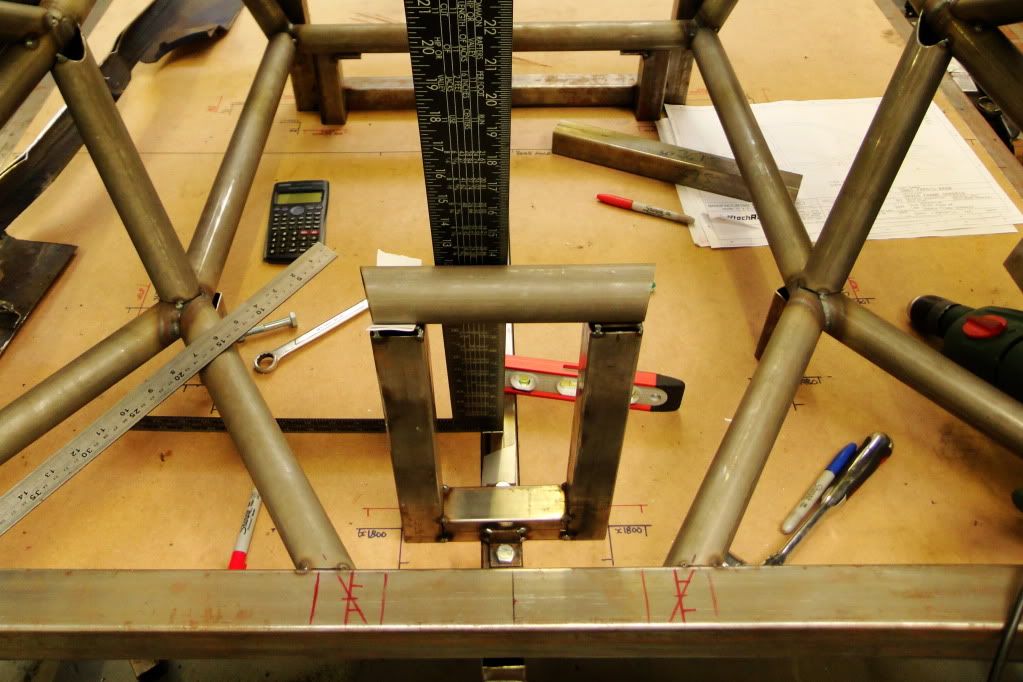
So then I set about levelling the shell on the stands, and building a flat level platform to take some measurements from. I'd had the rough space-frame design made up using some pretty basic technical drawings I found on the internet, but needed some good measurments to confirm everything. It was basically all done with string, tape measures, pencils and rulers.

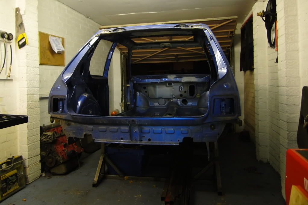
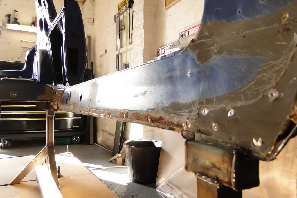
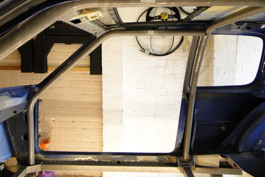
To do that, I chopped out the floor and started to install the ROPS (roll-over protection structure) which came from an MSA approved Custom Cages shell. I had some sill reinforcement rails made up, then went about fitting the hoops. I opted to follow the MSA regs on foot-plate sizes - it seemed to be a bit of a grey area with the rules and space-frames, so may not have been necessary, but I didn't want to run into any problems with scrutineers once the thing was built!

I used those few parts to measure the ROPS and confirm / adjust my CAD model, then set about a series of FEA simulations to get a good ratio of stiffness to weight.
More to follow..
This thread will be exactly how all internet-featured projects should be: open, detailed, and full of pictures! So.. 56k GTFO before your modem implodes. (Sorry, I couldn't resist a dial-up joke) Anyway..
The basic concept is: space frame chassis; SLA suspension with push rod to damper; front engine - rear drive with 2.0 Duratec turbo, Drenth sequential gearbox, Ford 7" diff and all custom shafts; carbon bodywork with front & rear "clamshells", CFD developed aero (as if an 80's brick could be aerodynamic..) with an emphasis on light weight at all times - predicted weight is 600kg with driver, and power output is to be in the region of 350bhp.
It started with a year of solid design work, then about this time 2 years ago I went out and bought a 1.6 Auto base model to use as the "donor".
It wouldn't stay like that for long, and was raised up on some home-made adjustable stands and duly torn to pieces.
So then I set about levelling the shell on the stands, and building a flat level platform to take some measurements from. I'd had the rough space-frame design made up using some pretty basic technical drawings I found on the internet, but needed some good measurments to confirm everything. It was basically all done with string, tape measures, pencils and rulers.
To do that, I chopped out the floor and started to install the ROPS (roll-over protection structure) which came from an MSA approved Custom Cages shell. I had some sill reinforcement rails made up, then went about fitting the hoops. I opted to follow the MSA regs on foot-plate sizes - it seemed to be a bit of a grey area with the rules and space-frames, so may not have been necessary, but I didn't want to run into any problems with scrutineers once the thing was built!
I used those few parts to measure the ROPS and confirm / adjust my CAD model, then set about a series of FEA simulations to get a good ratio of stiffness to weight.
More to follow..
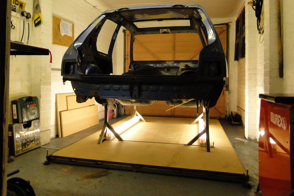
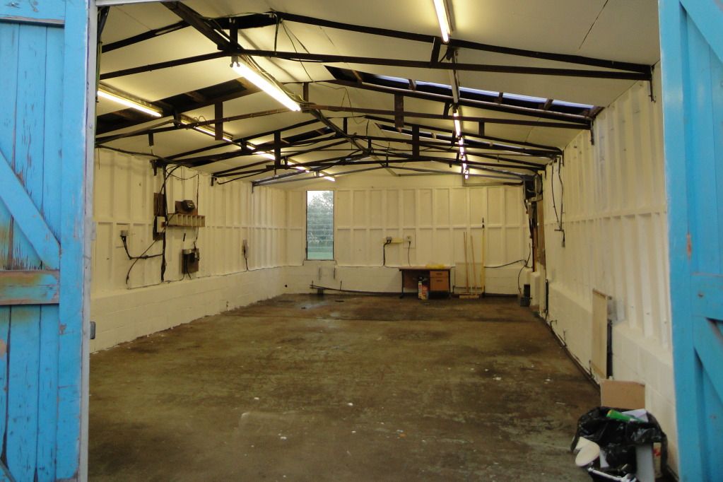
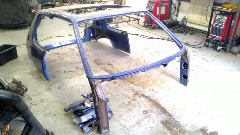
Things started getting a little cramped in that single garage, and looking back I have no idea how I thought I'd be able to build the whole thing in there! I found a cheap unit with a couple of mates, then after a bit of cleaning and painting, moved my car in.
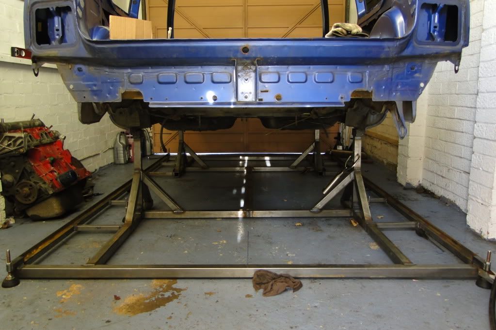
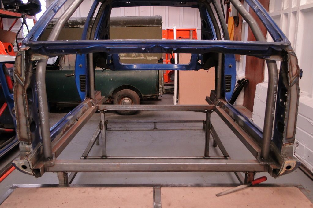
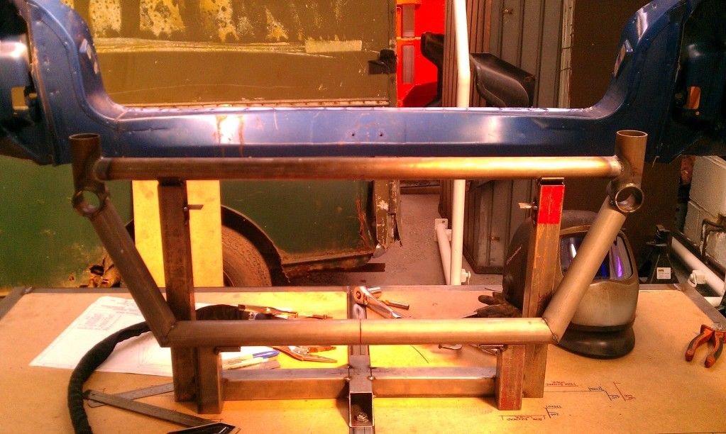
I had to build a new measuring platform, and with all that space figured I'd do a slightly more elaborate job this time. I got the car up in the air, first of all, then built the frame around it. I gave it a replaceable wood surface that I could scribble all over and made the front & rear platforms removable so that I could get good welding access later.


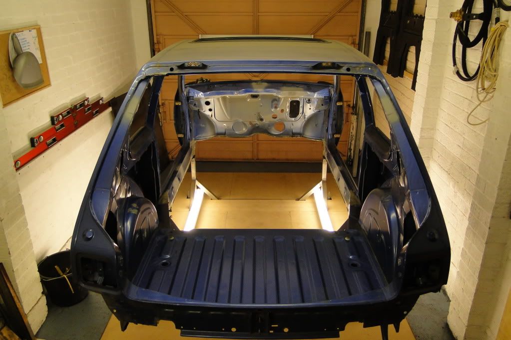
Then I built up a jig for the front panel (I'd need it later) and started hacking the shell to pieces.
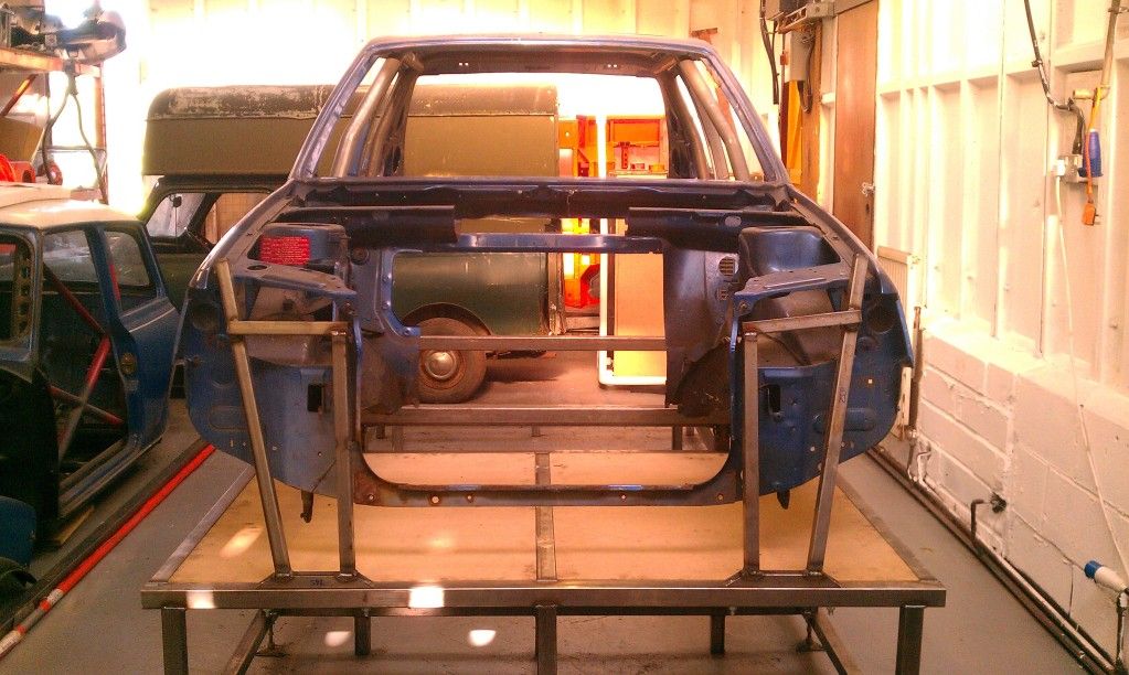


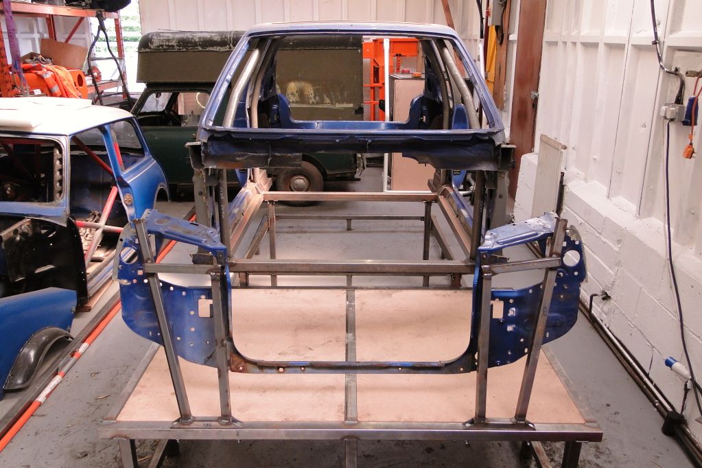
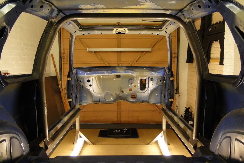
Then finally tidied up the A-pillars and welded over all the holes.
More to follow..
I had to build a new measuring platform, and with all that space figured I'd do a slightly more elaborate job this time. I got the car up in the air, first of all, then built the frame around it. I gave it a replaceable wood surface that I could scribble all over and made the front & rear platforms removable so that I could get good welding access later.
Then I built up a jig for the front panel (I'd need it later) and started hacking the shell to pieces.
Then finally tidied up the A-pillars and welded over all the holes.
More to follow..
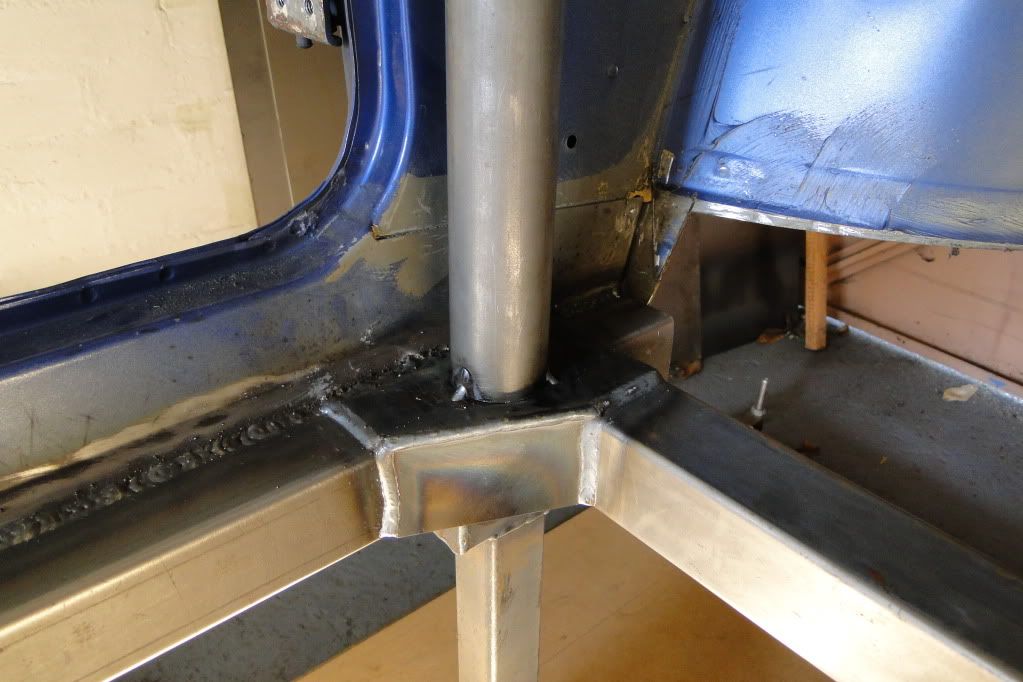
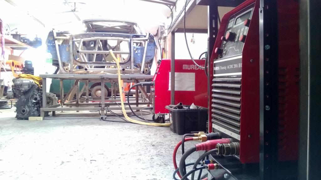
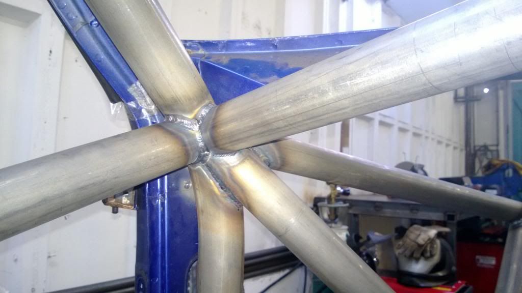
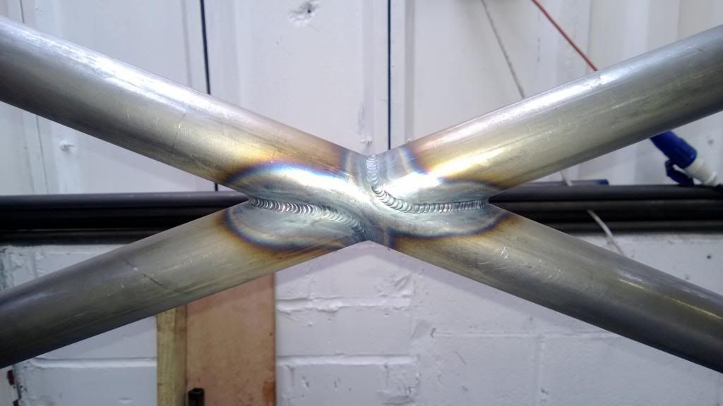
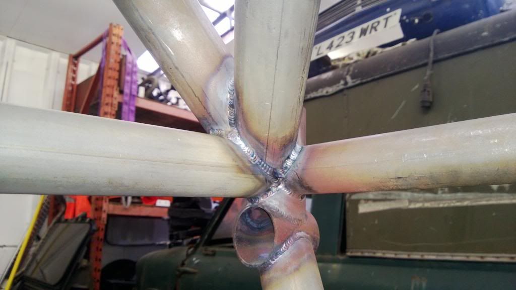
At this point (around August 2012) I hadn't done any TIG since my final year of uni on 2010, so I was really keen to get back in to it. I bought a Murex Transtig AC/DC unit 2nd hand and set it up with a good torch so I could get going. I decided to start at the back of the car and work forwards, as I was still working on steering geometry, so made the rear bulkhead and went from there.

I got some practise in then went for it..
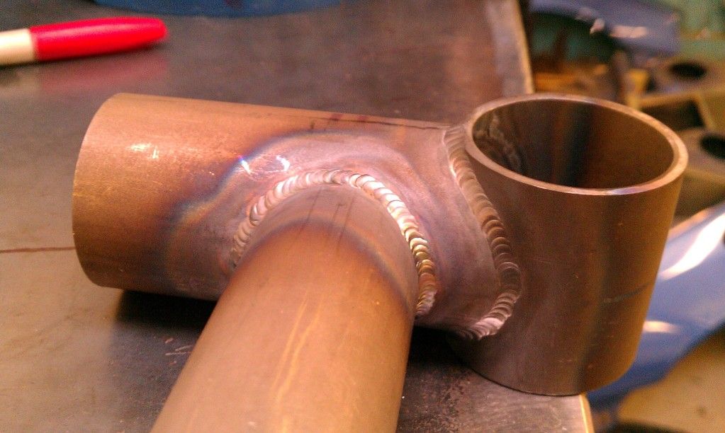
Then started to tie the bulkhead back in to the ROPS.
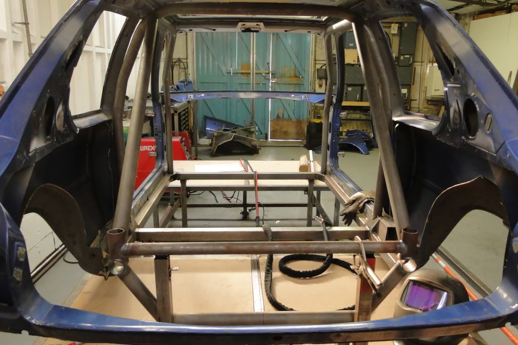
Good fits being essential for TIG!
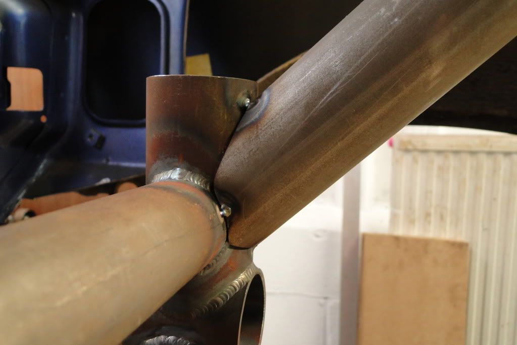
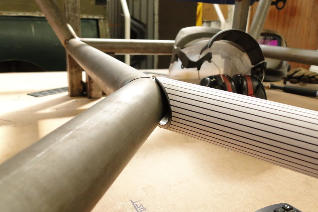
For those who are intertested, I used the following method to vastly simplify the process of profiling joints:
1 - Extracted tube surface from CAD model andp rinted out 1:1 it can be wrapped around the tube.
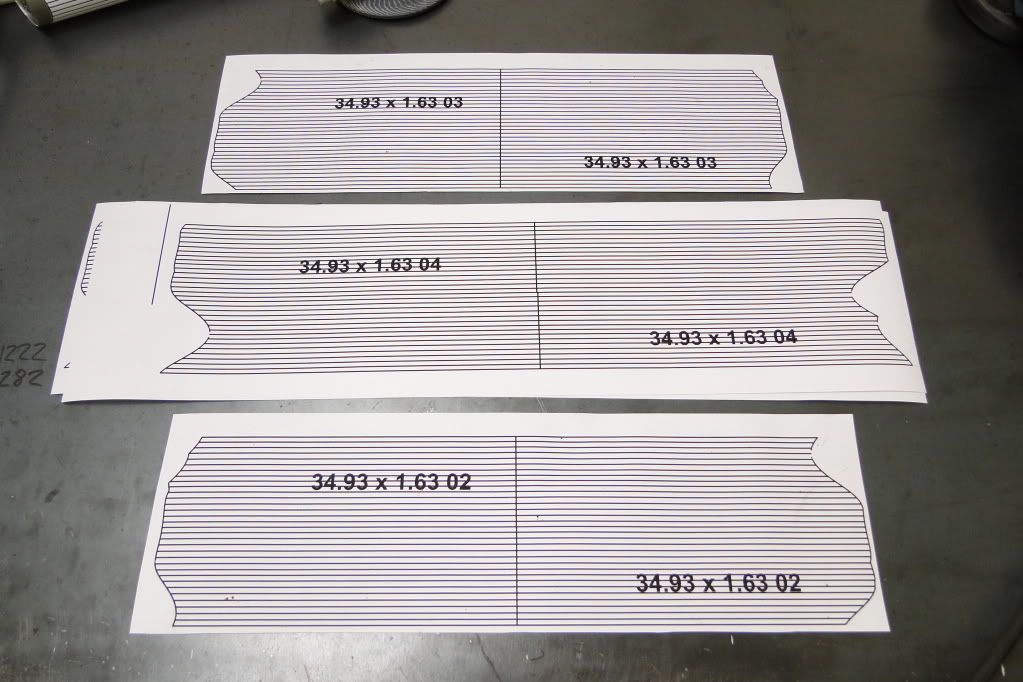
2 - Although that doesn't make the joint perfect, as the surface print-out assumes zero thickness; there's still a little to be done to get the fit right.


I got some practise in then went for it..
Then started to tie the bulkhead back in to the ROPS.
Good fits being essential for TIG!
For those who are intertested, I used the following method to vastly simplify the process of profiling joints:
1 - Extracted tube surface from CAD model andp rinted out 1:1 it can be wrapped around the tube.
2 - Although that doesn't make the joint perfect, as the surface print-out assumes zero thickness; there's still a little to be done to get the fit right.
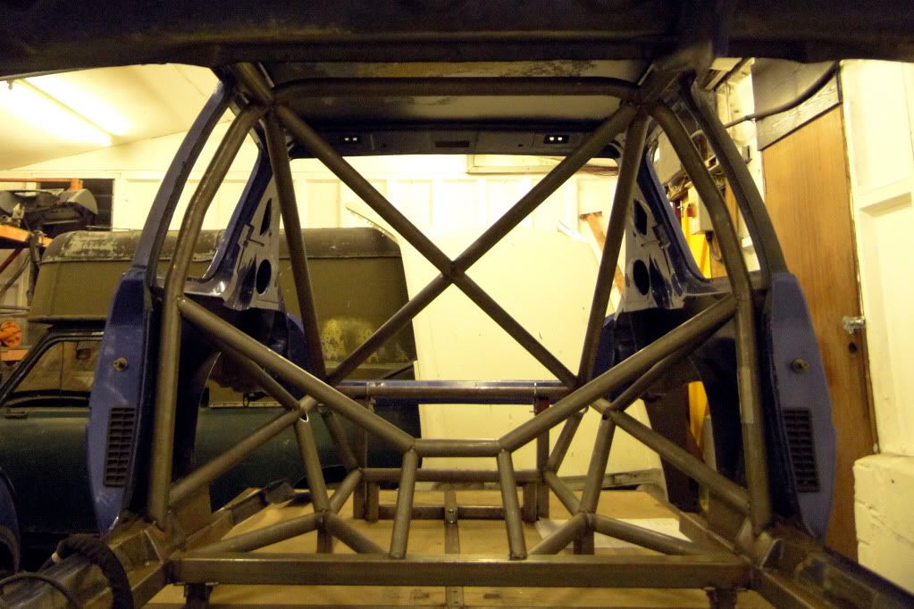
Lots and lots of cutting & profiling later.. I had the rear end finished.
I could then start on the front! (A recurrent theme of this project is I love building jigs) I opted for a Caterham CSR steering rack, which I duly bought and measured so I could get my front geometry finished and get started on the frame.
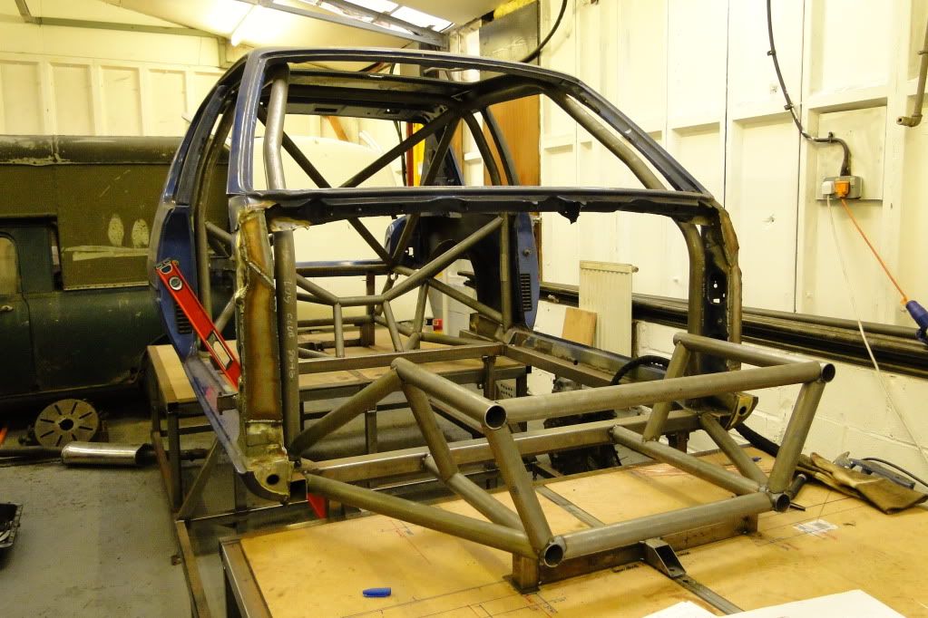
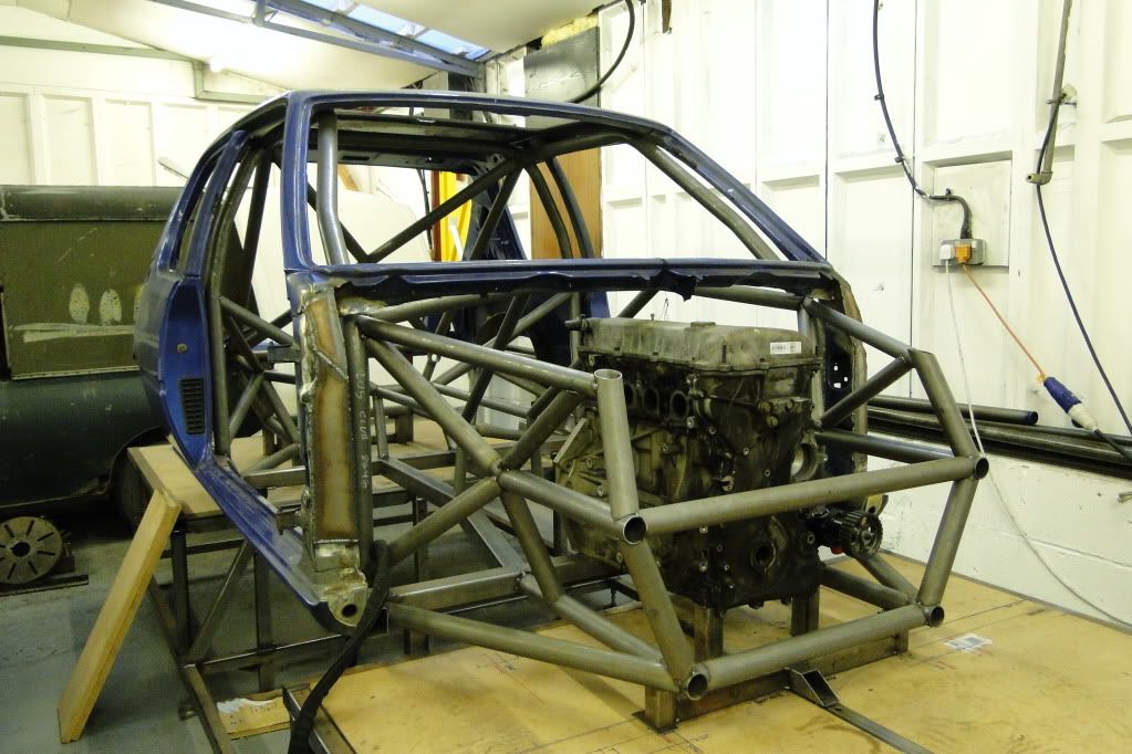
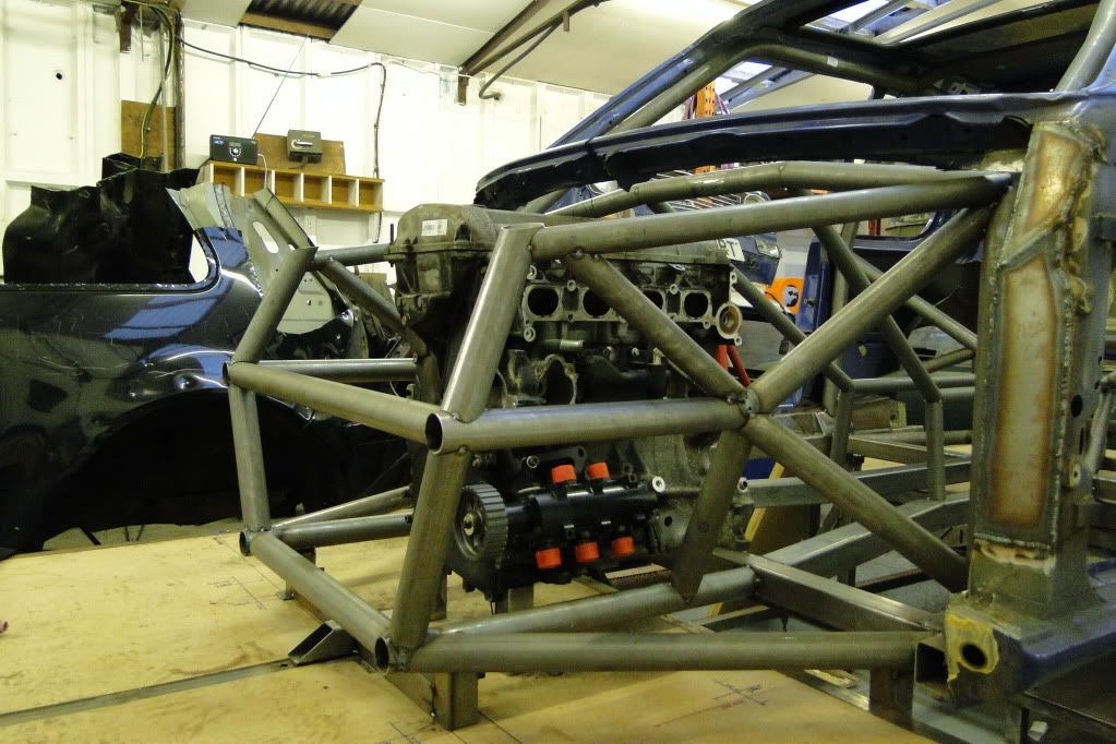
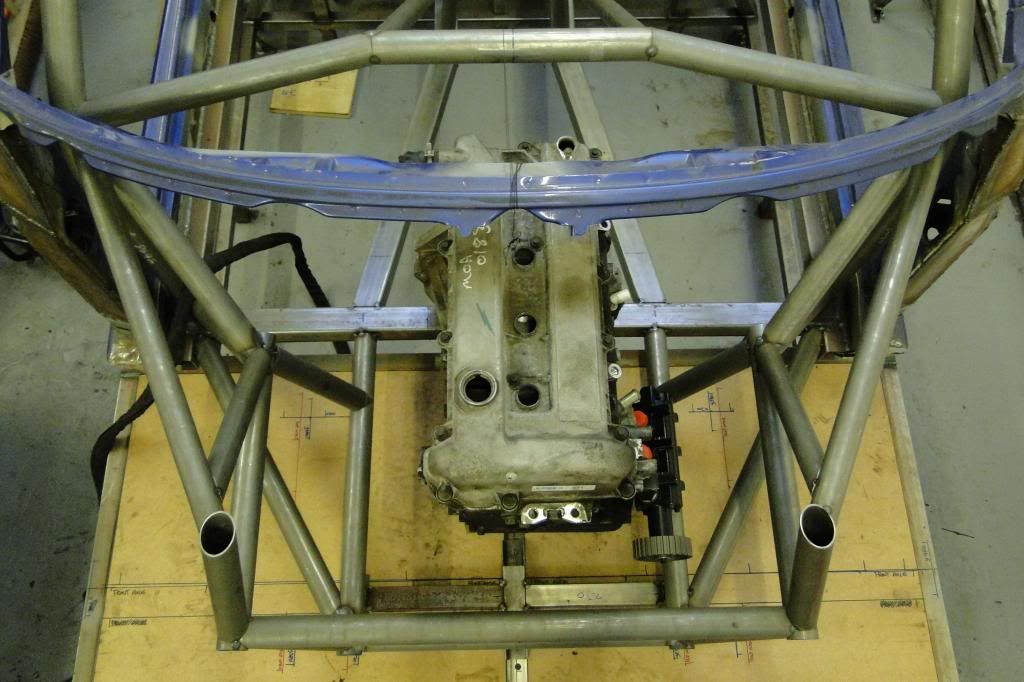
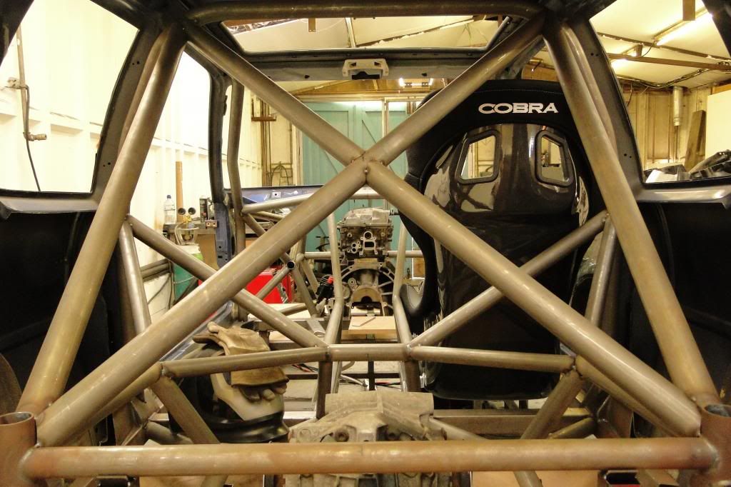
I put the engine in so I could confirm clearances before I went and welded everything up, as I was a little worried about being able to get it in / out and having enough clearance for the oil pump. There'll be a removeable aloooominum engine X-brace over the top that will stiffen the front end up.
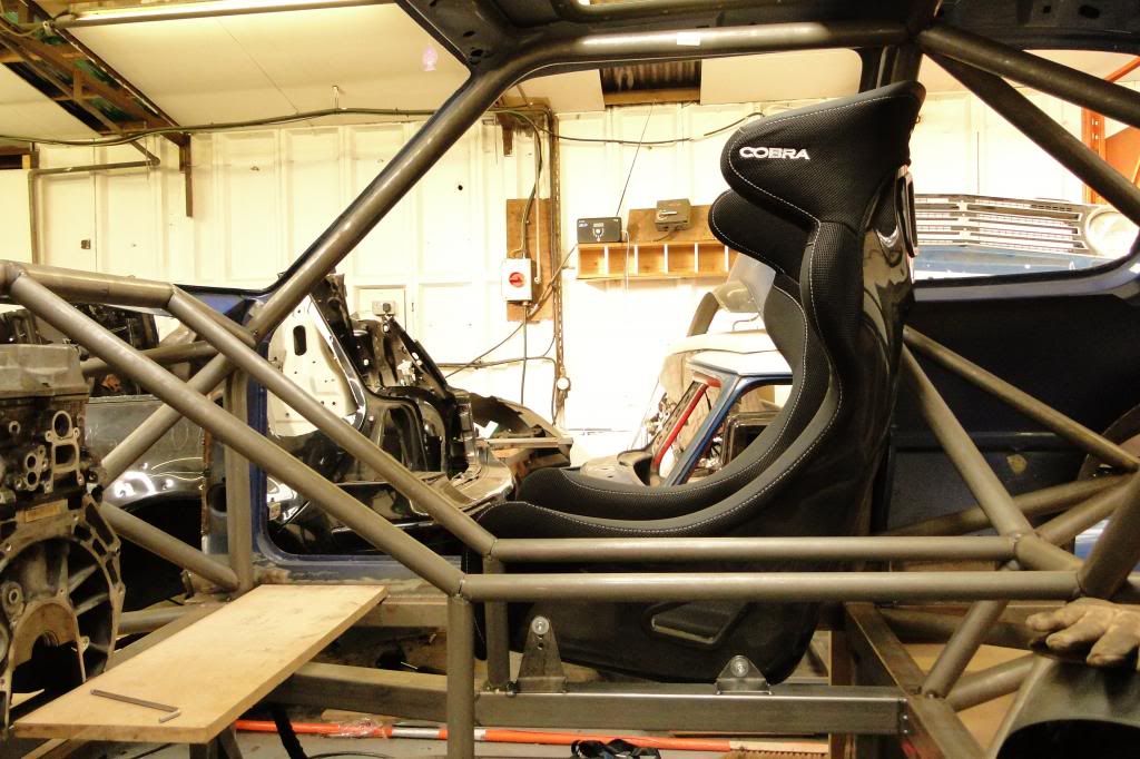
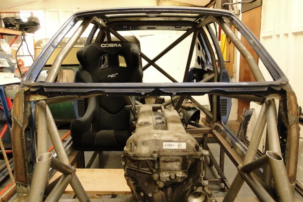
I got myself a nice light carbon seat (lightest I could find for a reasonable price) and checked that it would fit. It didn't. So I had to modify the trans tunnel slightly and narrow it enough to fit.
More to follow!
I could then start on the front! (A recurrent theme of this project is I love building jigs) I opted for a Caterham CSR steering rack, which I duly bought and measured so I could get my front geometry finished and get started on the frame.
I put the engine in so I could confirm clearances before I went and welded everything up, as I was a little worried about being able to get it in / out and having enough clearance for the oil pump. There'll be a removeable aloooominum engine X-brace over the top that will stiffen the front end up.
I got myself a nice light carbon seat (lightest I could find for a reasonable price) and checked that it would fit. It didn't. So I had to modify the trans tunnel slightly and narrow it enough to fit.
More to follow!
Sorry I've been rattling through the updates so missed the comments! Thanks for the kind words everyone. 
That all takes things up to the beginning of this year. At this point I hadn't saved quite enough cash up for the gearbox I wanted, so bought a cheap T9 off eBay so I could line things up. I also got a Sierra Cosworth rear axle to steal the 7" diff out of as it seemed to be the best balance of cost, weight, FD options and performance. I also kept the hubs and stube axles, but all the other bits were ditched.
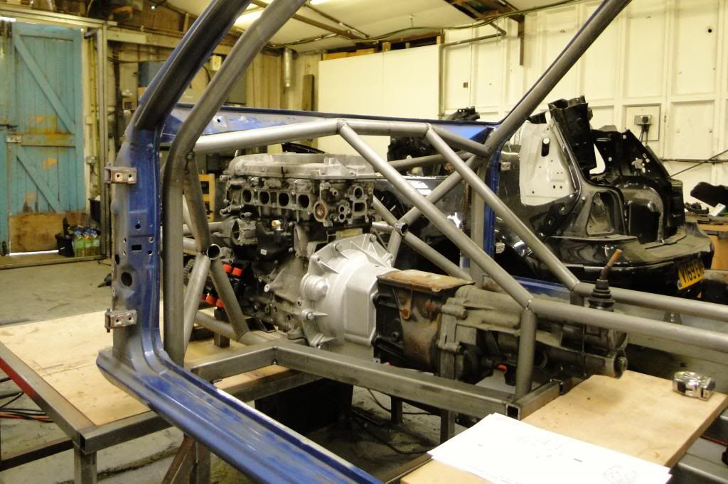

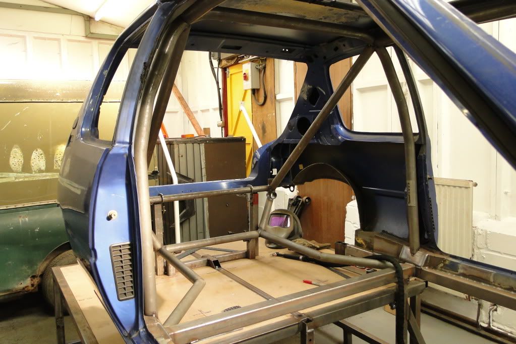
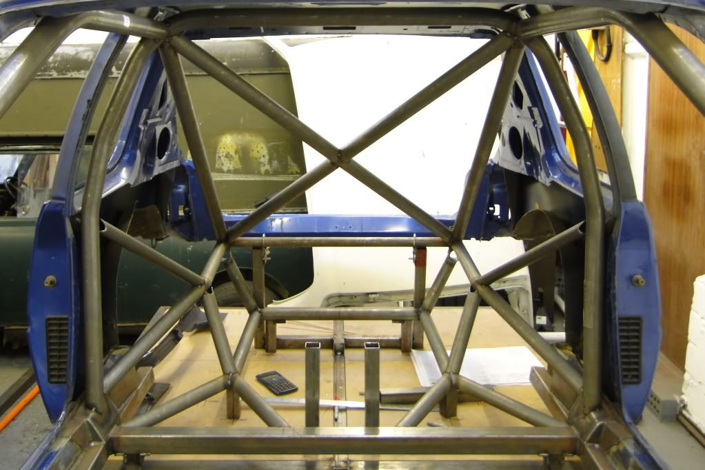
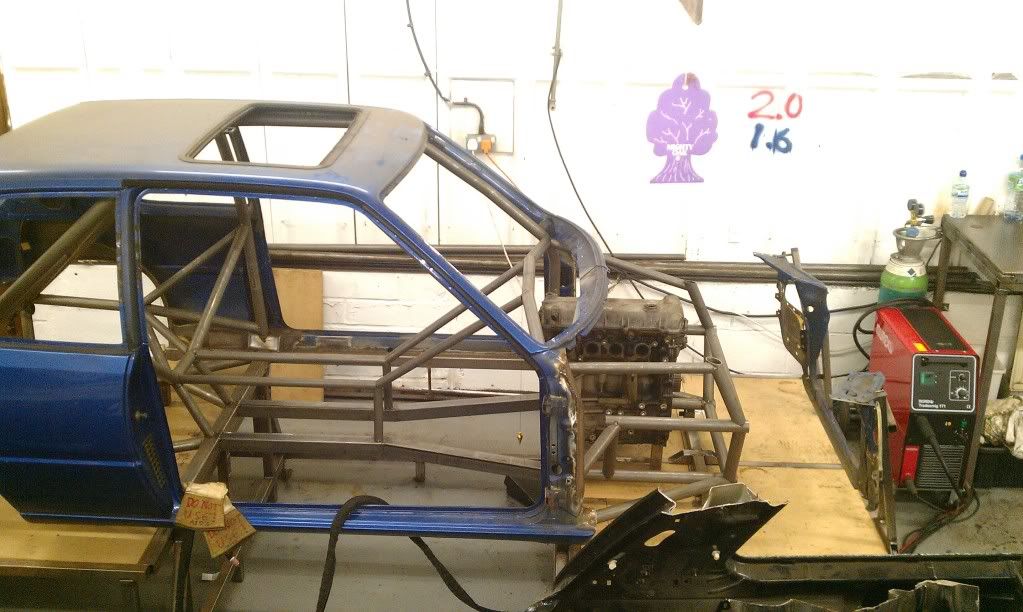
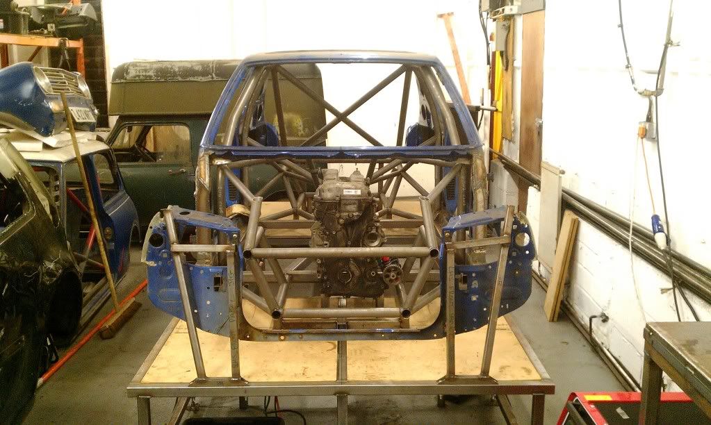
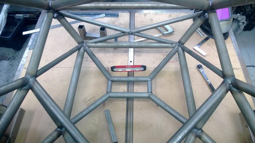
Once I was happy that all the main components would fit, I went and bought a water cooler then fully welded the basic frame up with my TIG.
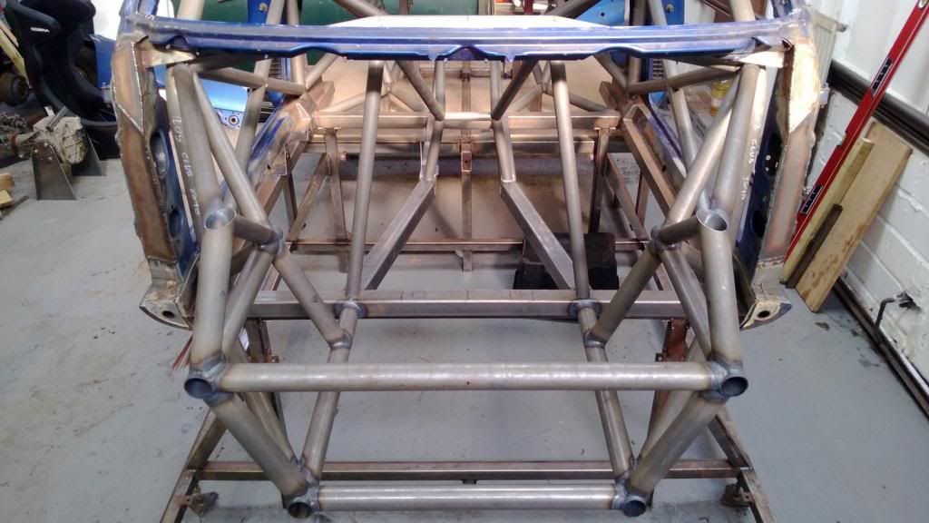
Then I cut the body off the frame to improve welding access to the roof & rear of the frame.
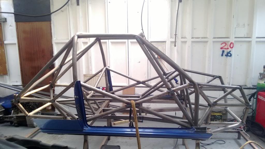
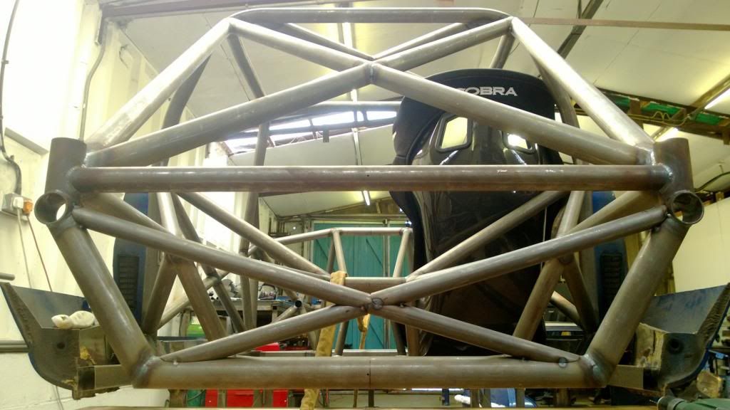
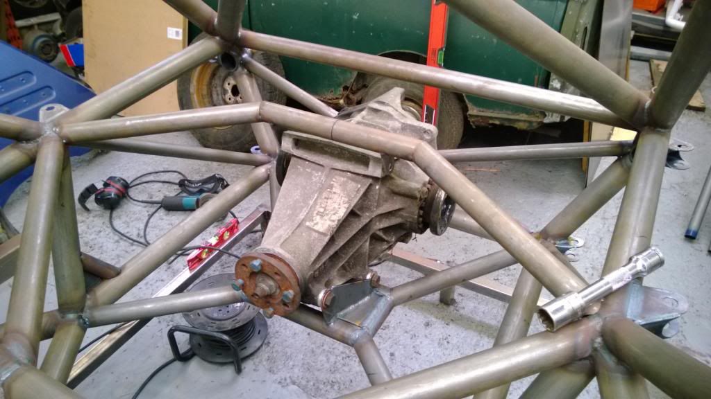
Once the basic frame was done, I could fit the remaining few braces and the rear diff mounting structure.
That all takes things up to the beginning of this year. At this point I hadn't saved quite enough cash up for the gearbox I wanted, so bought a cheap T9 off eBay so I could line things up. I also got a Sierra Cosworth rear axle to steal the 7" diff out of as it seemed to be the best balance of cost, weight, FD options and performance. I also kept the hubs and stube axles, but all the other bits were ditched.
Once I was happy that all the main components would fit, I went and bought a water cooler then fully welded the basic frame up with my TIG.
Then I cut the body off the frame to improve welding access to the roof & rear of the frame.
Once the basic frame was done, I could fit the remaining few braces and the rear diff mounting structure.
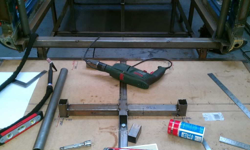
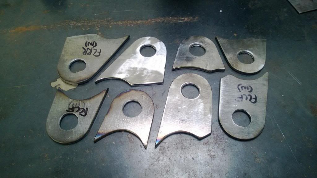
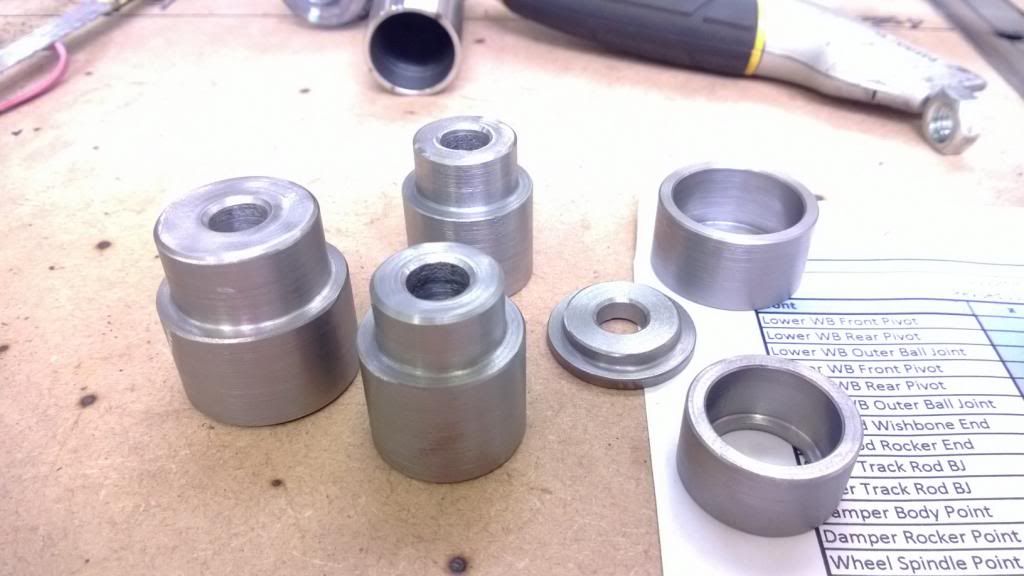
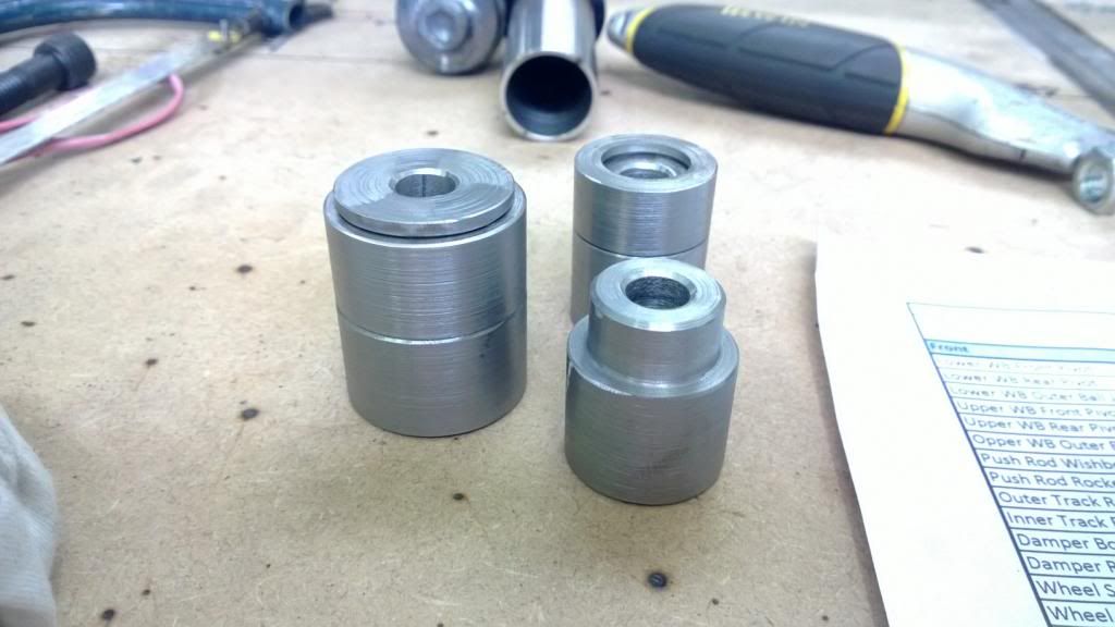
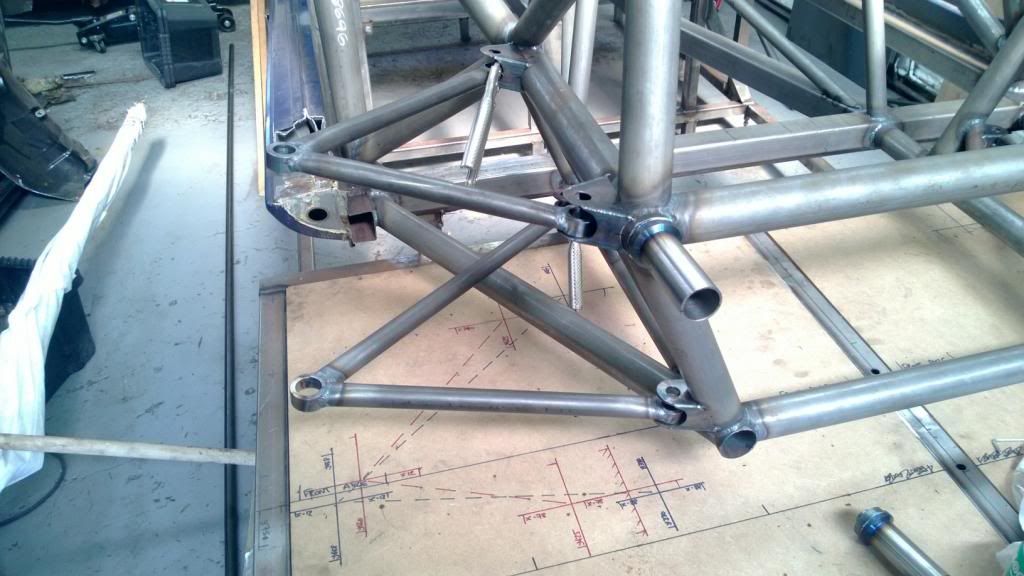
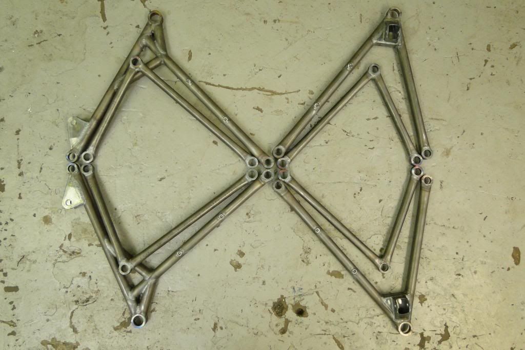
Then I got on to making the suspension brackets, starting with the wishbone mounts. I machined up a little 3-piece spacer to get the holes concentric and ensure the correct spacing. Then used the surface table to position them on the frame to be welded in place.
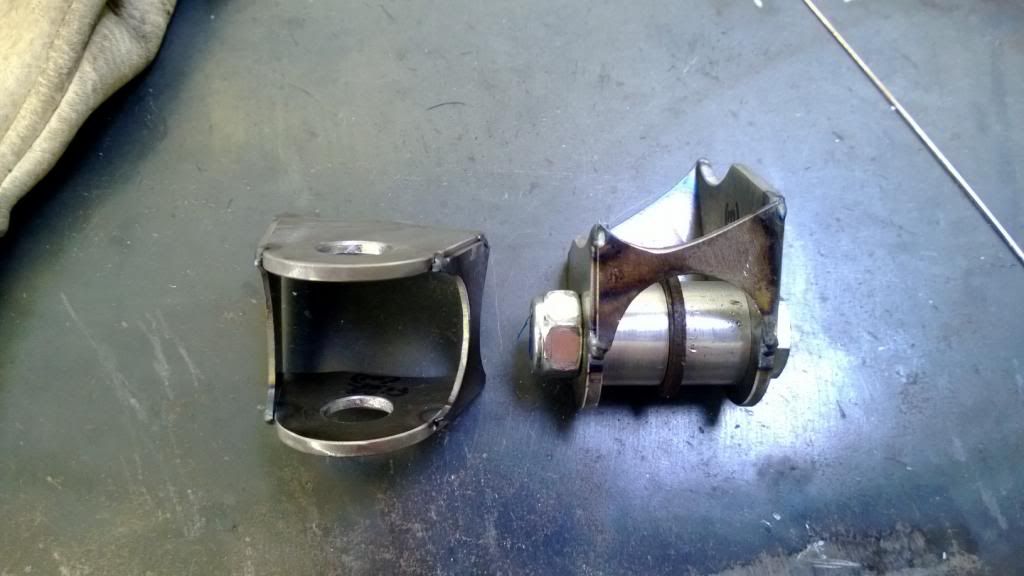
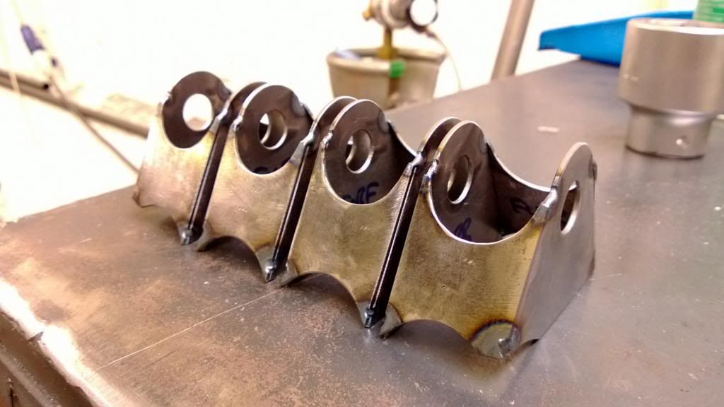
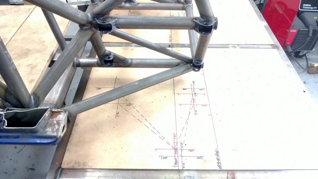
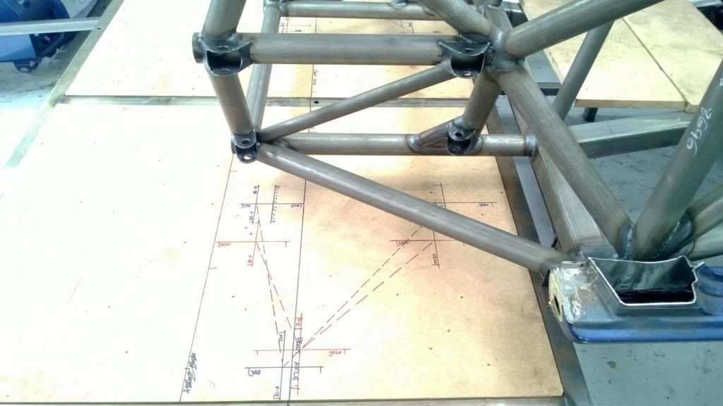
I think these were the first CNC bits I'd hade machined, and are the front / rear subframe mounts. I wanted to have the front / rear bodywork and crash structure removeable so that any minor accidents wouldn't ruin the whole chassis; the majority of aero loads will also run through these so I needed a good strong way of transferring that into the frame. I turned down some socket screws (all about the weight saving..) and welded them captive, the result is a very good positive location.
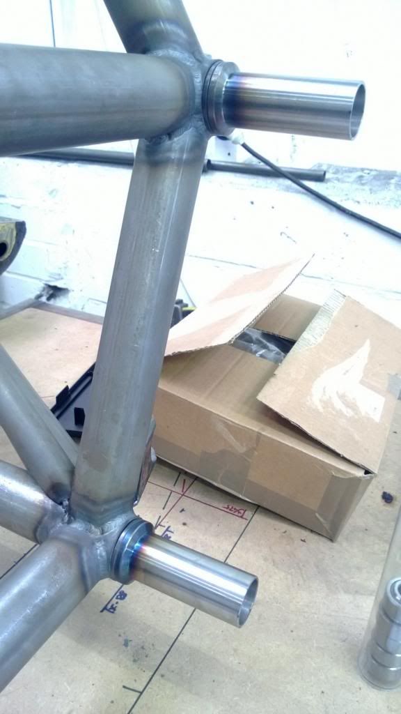
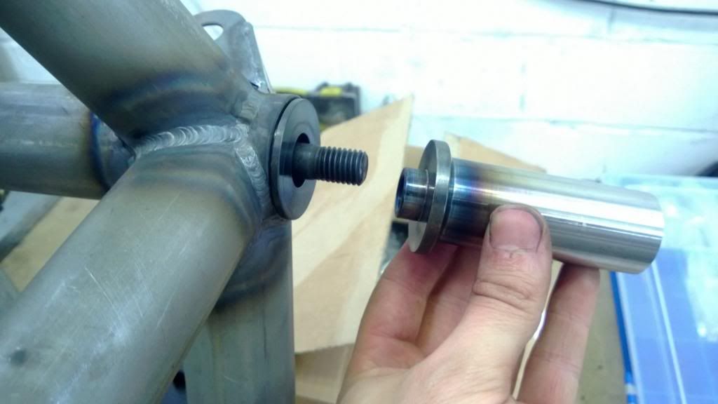
I think these were the first CNC bits I'd hade machined, and are the front / rear subframe mounts. I wanted to have the front / rear bodywork and crash structure removeable so that any minor accidents wouldn't ruin the whole chassis; the majority of aero loads will also run through these so I needed a good strong way of transferring that into the frame. I turned down some socket screws (all about the weight saving..) and welded them captive, the result is a very good positive location.
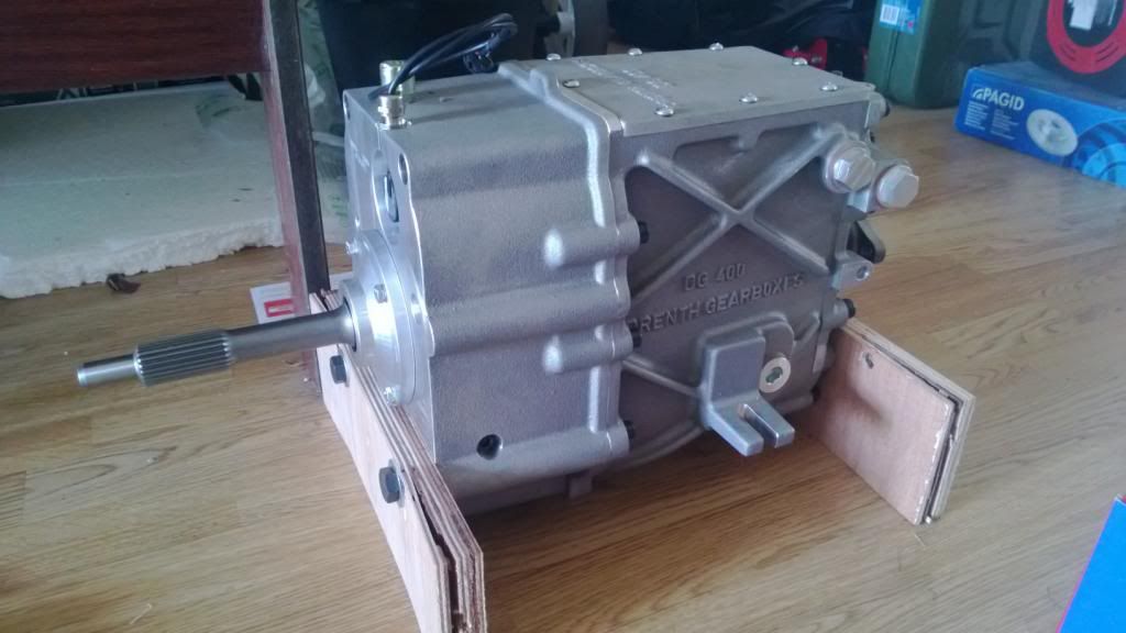
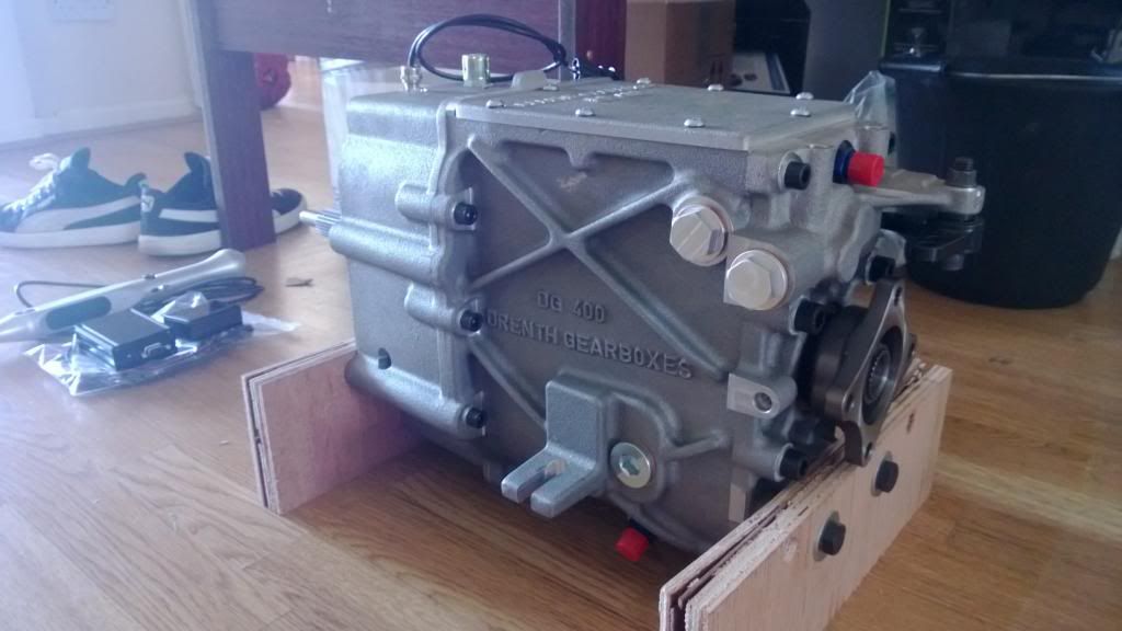
I think I'll make this the final post of today! After a lot of saving pennies I placed my gearbox order, then after a bit of a wait for it to be built up I got a present. 
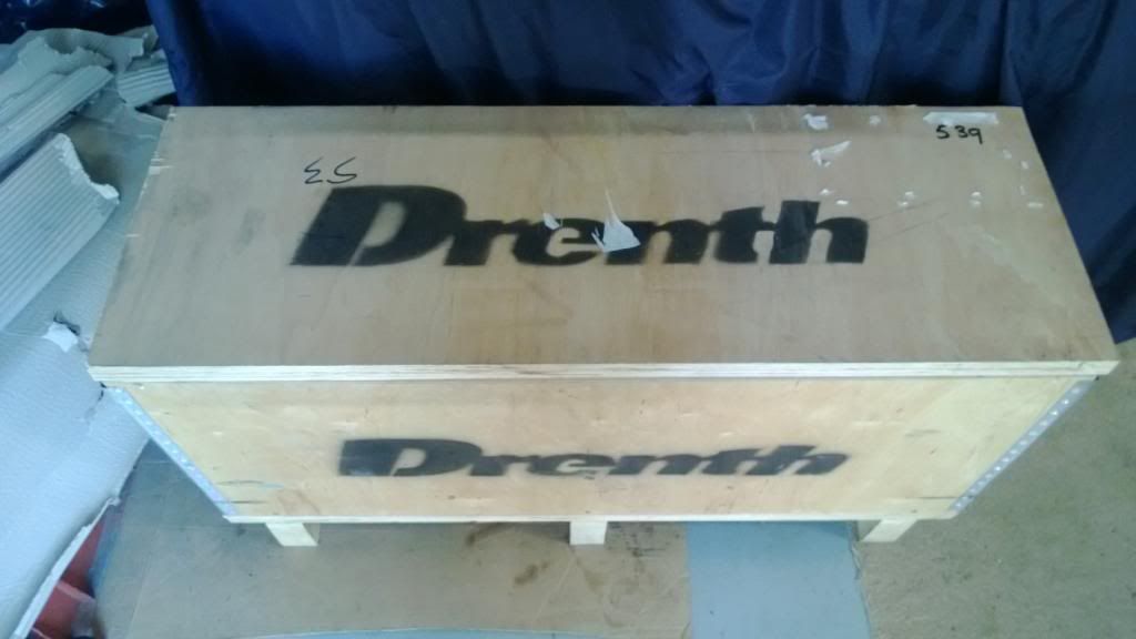
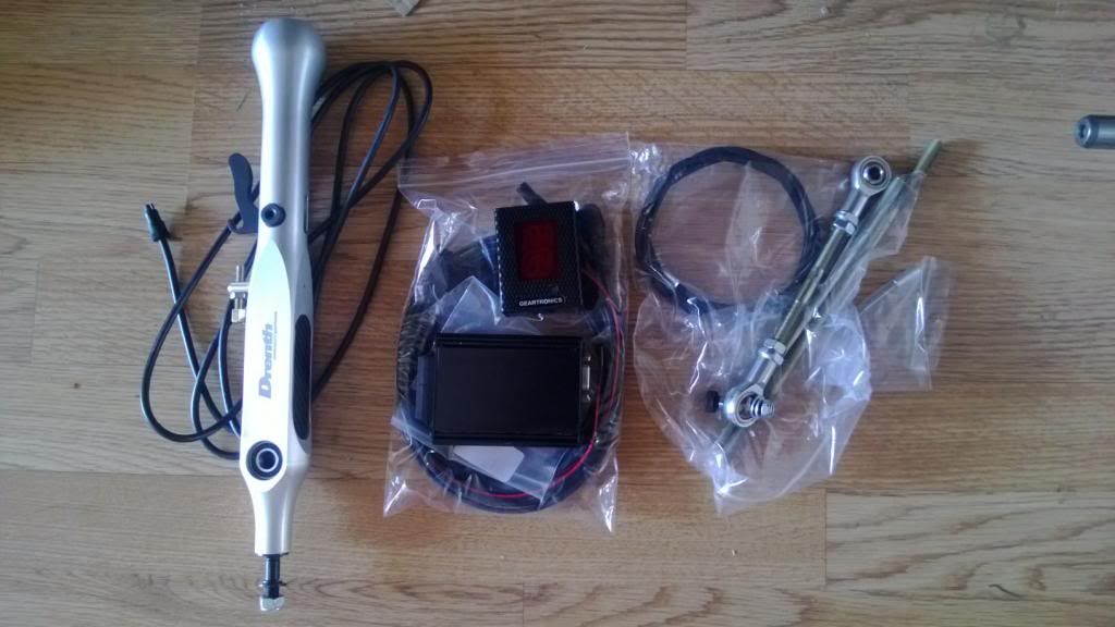
It's a Drenth DG-400, which is a 6-speed sequential dog box - and quite a nice one at that! It's T9 fitment so is ideal for mating to the Duratec, and has custom ratios to suit my application. I also went for a strain-guaged flat shift lever and Geartronics control system. I had wanted to go paddle-shift but it was just a bit too expensive and I needed to draw a line somewhere.
I think that takes things up to about May this year, so there's still a fair bit to follow. Thanks for reading so far!
Haha yes I was at UH in 2010.. on the FS team.
GC8 - Red motorsport spirit levels are available from all good Screwfix stores, if you're interested.
Caddyshack - I had originally planned to do a T16 / Dimma kit, but I didn't want people to think it was just another Dimma, so decided to go for some minimal Berg Cup style arch extensions instead.
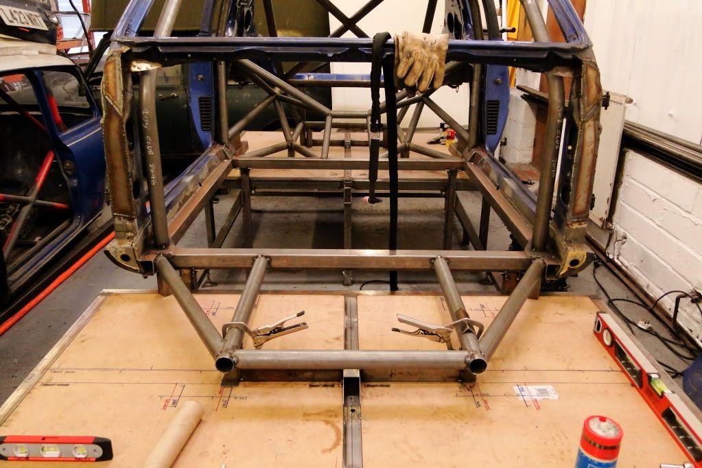
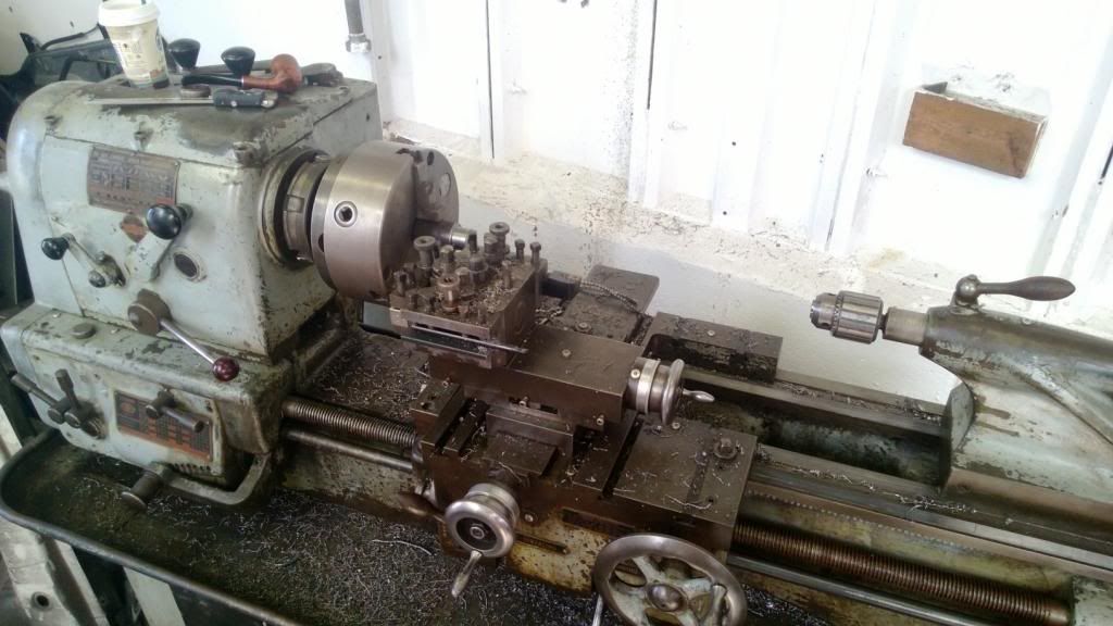
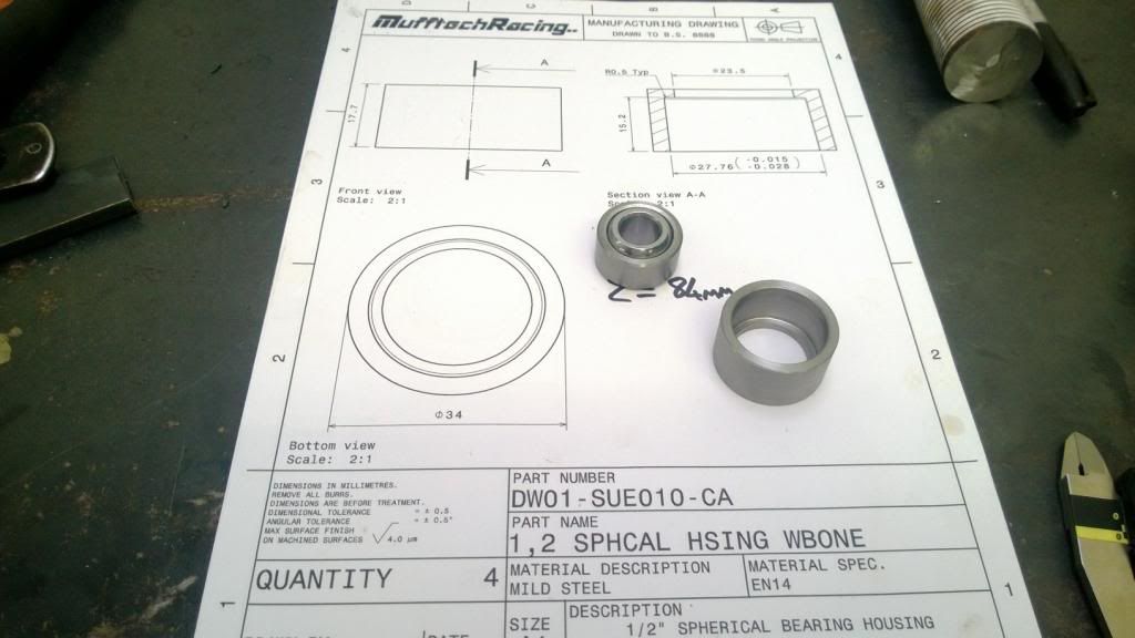
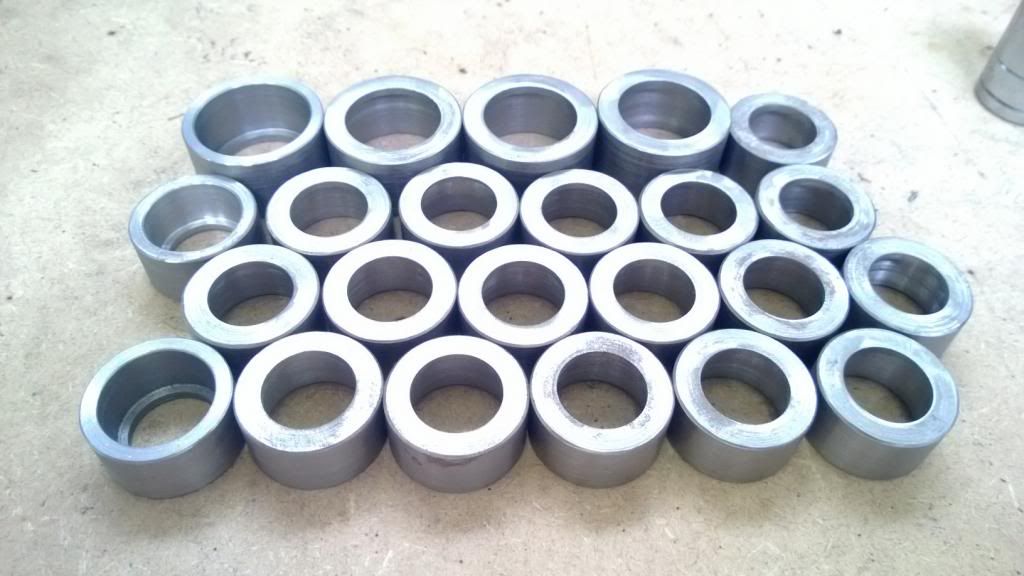
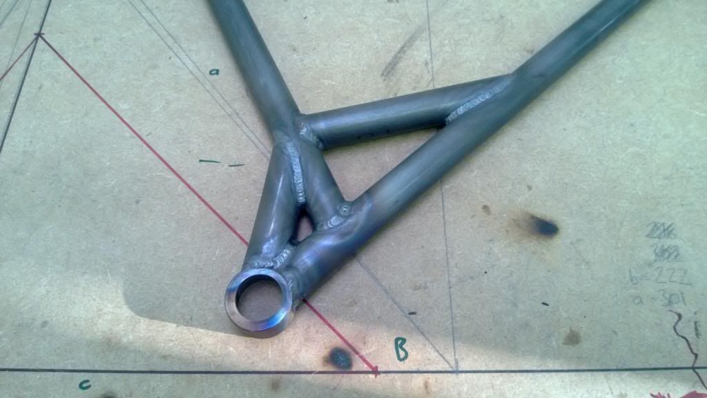
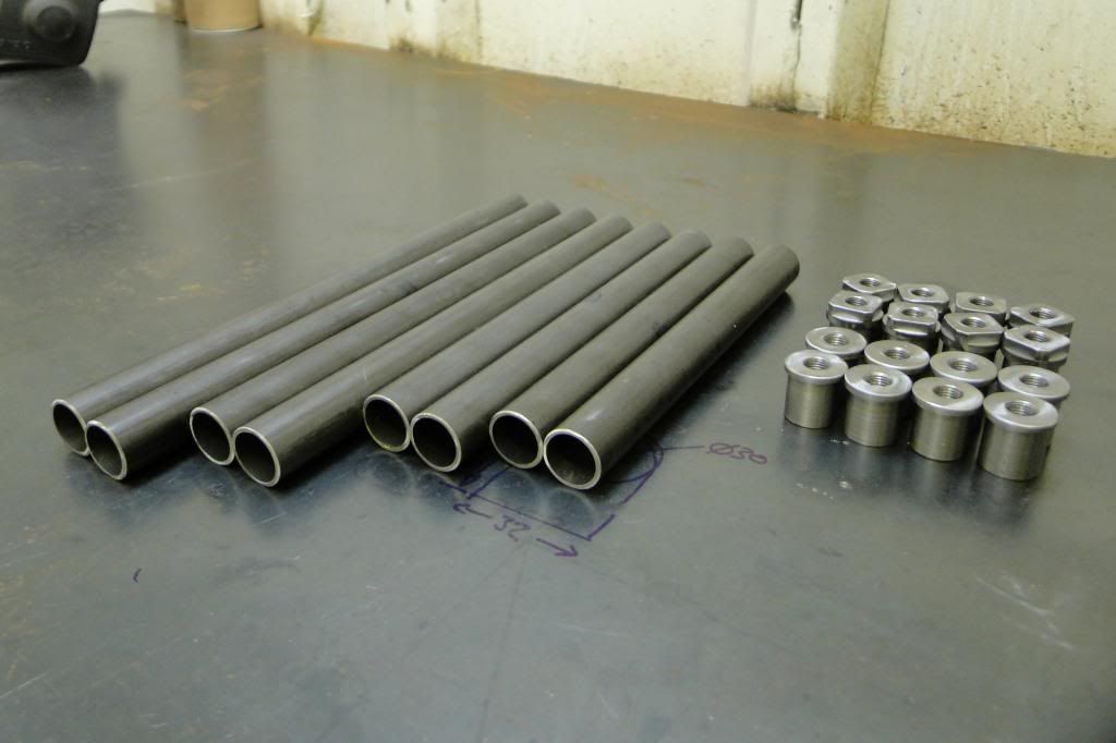
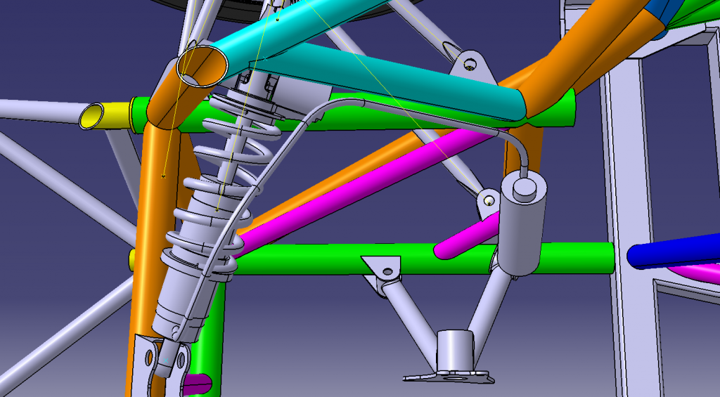
The next thing I got on with was making all the wishbones, which started with churning out a whole load of bearing housings on the lathe. I went down after work every night for about 2 weeks until eventually I had a big enough pile. The wisbones were made with T45 tube and EN14 housings.
Then made a few modular jigs so I could get the height & spacing right so all the sphericals were in-plane, and made up some frames to bolt them down to.
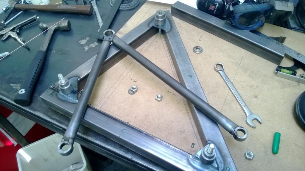
Don't worry, the lower wishbone doesn't come near that chassis member in rebound!
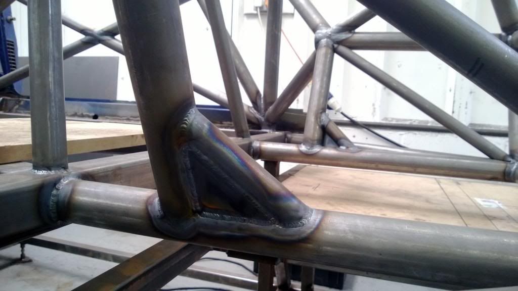
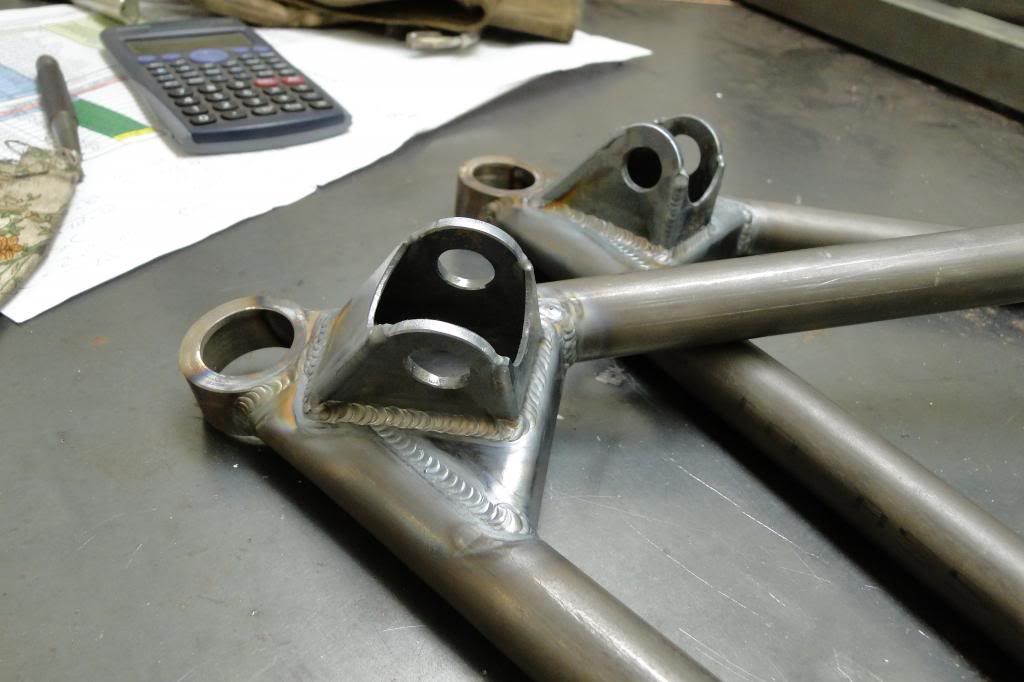
The front lowers got a gusset and push rod bracket, and the rear lowers needed a fairly large cantilever to clear the wheel rims. I think the rear lowers are my favourite bit so far.
Then the last thing to do was fit some pressed washers to secure the flexible brake lines to (I'll use tiny zip ties) and they were ready for powder coating.
GC8 - Red motorsport spirit levels are available from all good Screwfix stores, if you're interested.
Caddyshack - I had originally planned to do a T16 / Dimma kit, but I didn't want people to think it was just another Dimma, so decided to go for some minimal Berg Cup style arch extensions instead.
The next thing I got on with was making all the wishbones, which started with churning out a whole load of bearing housings on the lathe. I went down after work every night for about 2 weeks until eventually I had a big enough pile. The wisbones were made with T45 tube and EN14 housings.
Then made a few modular jigs so I could get the height & spacing right so all the sphericals were in-plane, and made up some frames to bolt them down to.
Don't worry, the lower wishbone doesn't come near that chassis member in rebound!
The front lowers got a gusset and push rod bracket, and the rear lowers needed a fairly large cantilever to clear the wheel rims. I think the rear lowers are my favourite bit so far.
Then the last thing to do was fit some pressed washers to secure the flexible brake lines to (I'll use tiny zip ties) and they were ready for powder coating.
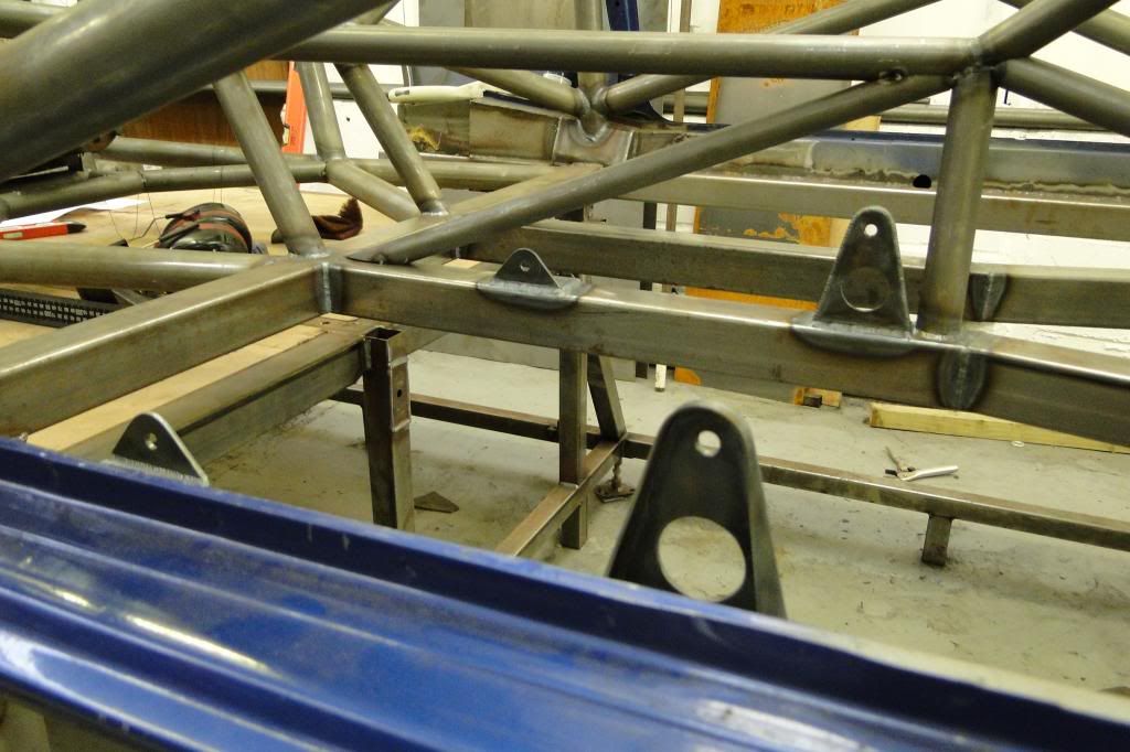
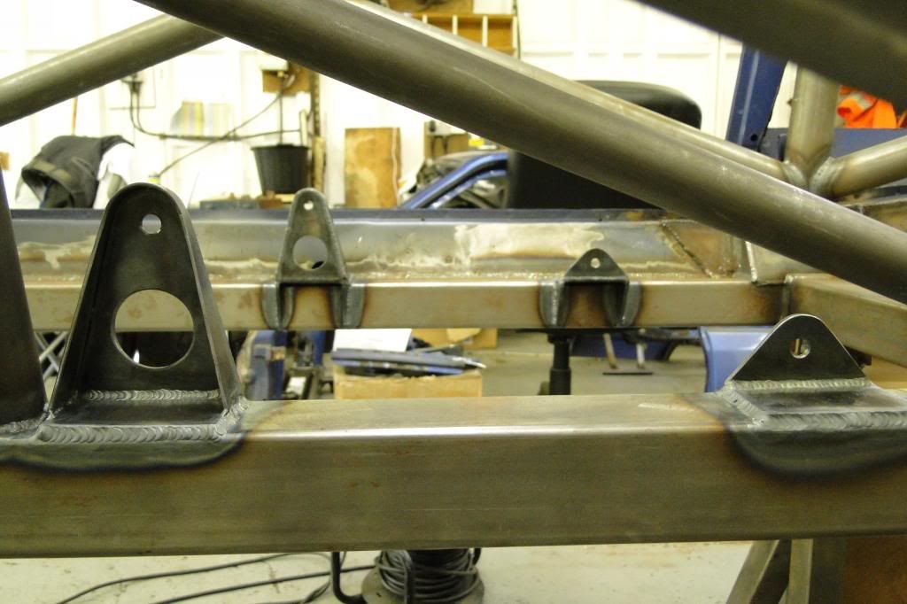
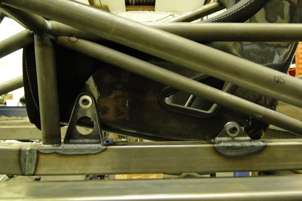
The next thing I did was put in some proper seat mounts, as it was previously only tacked in with some flimsy ones.. the new ones were made to MSA spec and welded in.
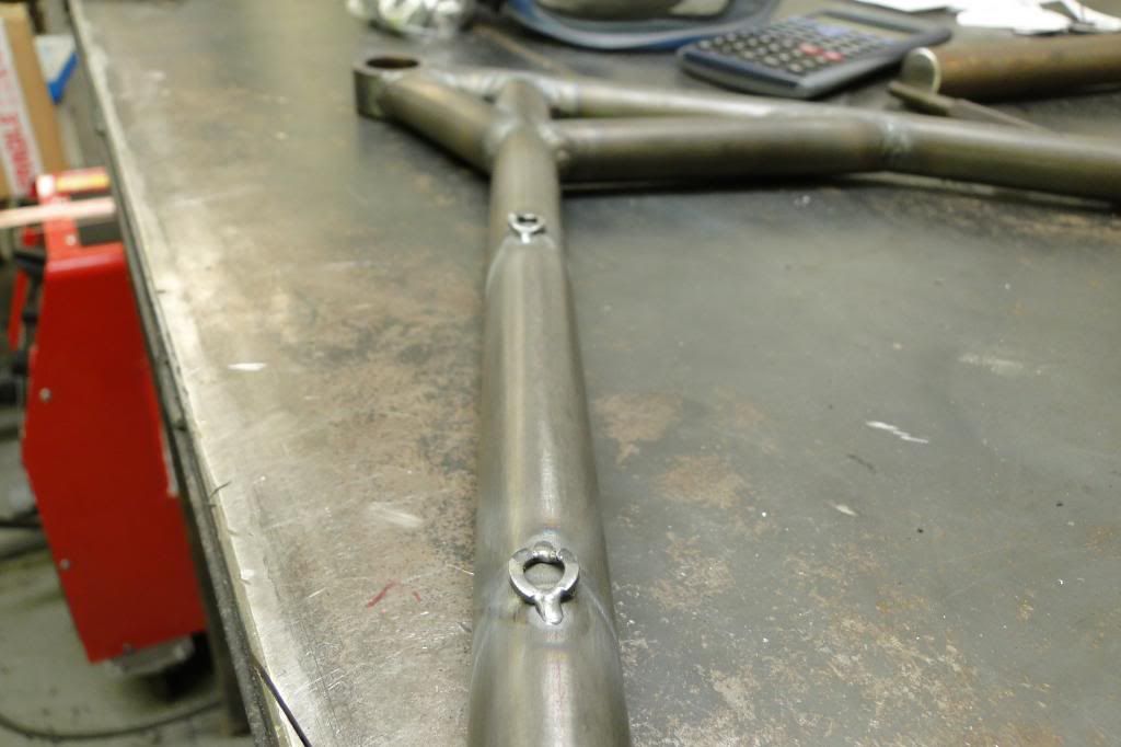
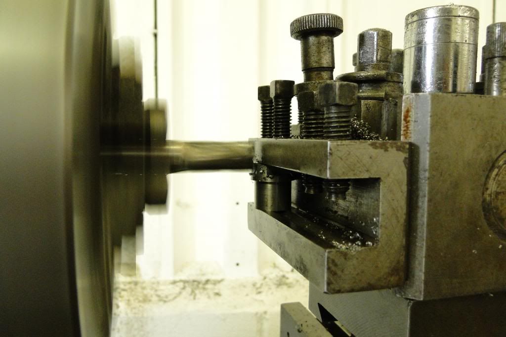
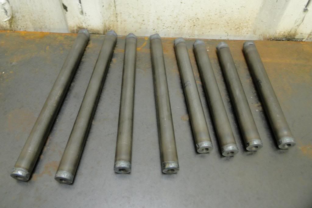
Then the next thing was making push & track rods.. I spent more long hours at the lathe turning the bosses up, and due to the lack of hex bar in a suitible grade (T45 rods, so needed EN14 bar) had to get creative with the lathe and an endmill. It was a fairly simple job to weld the bits together after that! I featured a poke-yoke by only adding flats to the RH threaded end, so it's easy to tell which way to turn the thngs without having to get up close and check the threads.
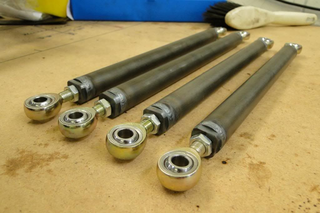
Those got sent off for powder coating along with the wishbones.
Then the next thing was making push & track rods.. I spent more long hours at the lathe turning the bosses up, and due to the lack of hex bar in a suitible grade (T45 rods, so needed EN14 bar) had to get creative with the lathe and an endmill. It was a fairly simple job to weld the bits together after that! I featured a poke-yoke by only adding flats to the RH threaded end, so it's easy to tell which way to turn the thngs without having to get up close and check the threads.
Those got sent off for powder coating along with the wishbones.
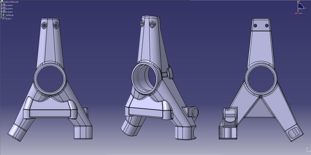
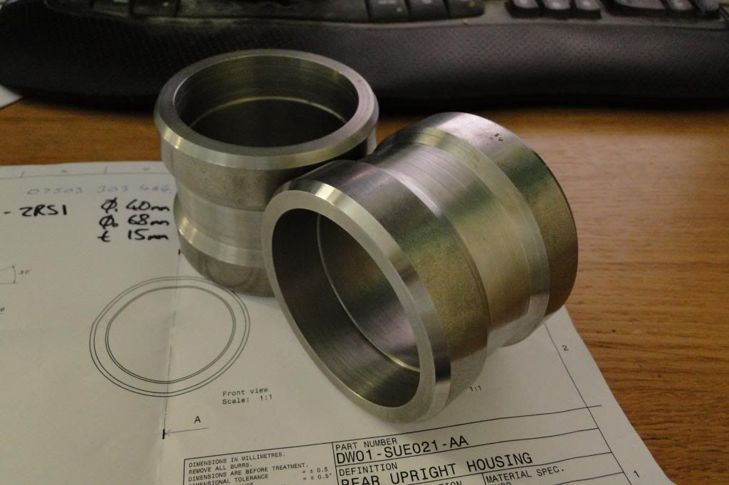
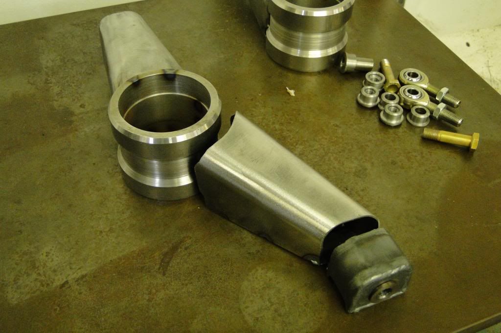
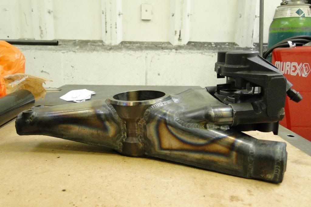
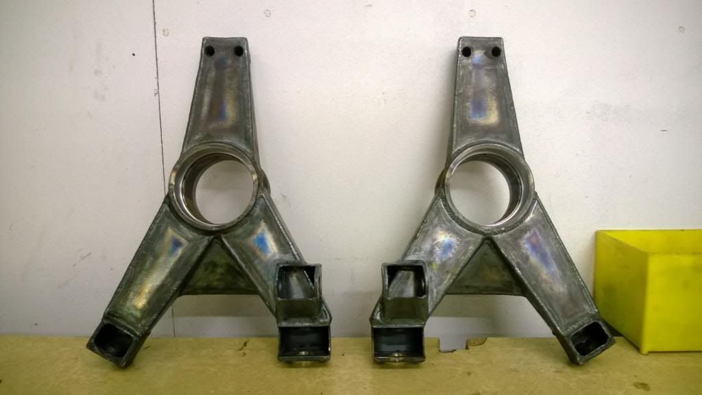
Then came my favourite bit of the project so far.. making the rear uprights. These, like everything else, started off as a CAD program, then ran FEA to check strength and a few iterations to try and reduce weight. I had a local CNC place machine up the centre bearing housings, then fabricated the rest.
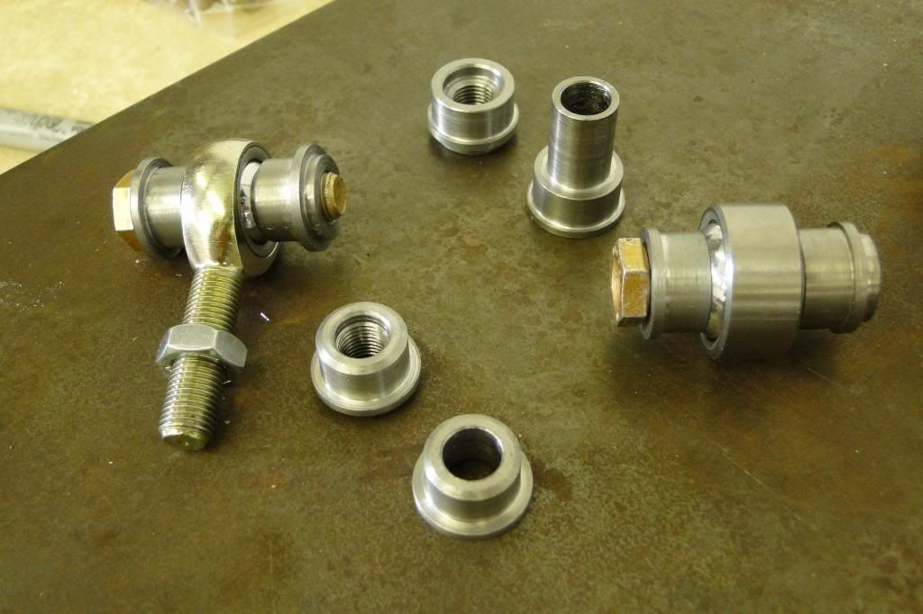
I turned the various bosses & spacers myself to save a bit of cash..
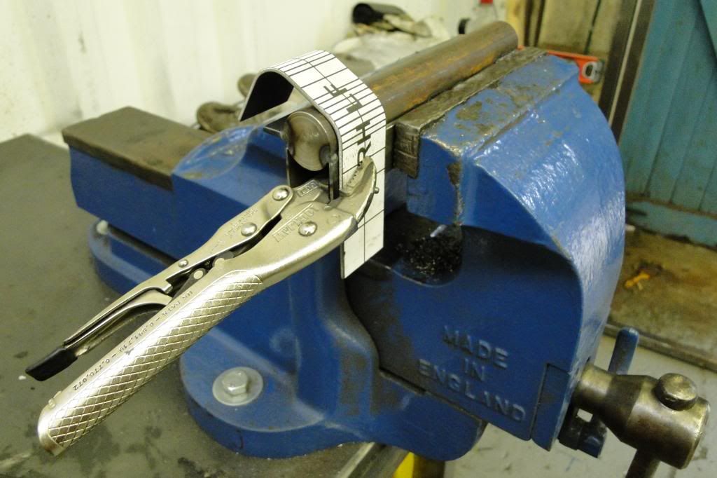
Since I didn't have a fly press or any other "proper" forming tools, I got creative with some bar stock and RHS to make a little tool I could use in the vice to form the curved edges. I picked up an old surface plate off eGay that I used as a jig table, and made a few fixtures up to hold everything in place for welding.
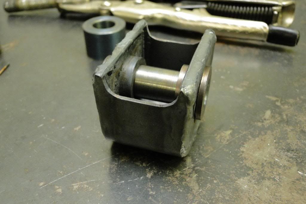
Then I could start forming the "legs" and welding the bits together.

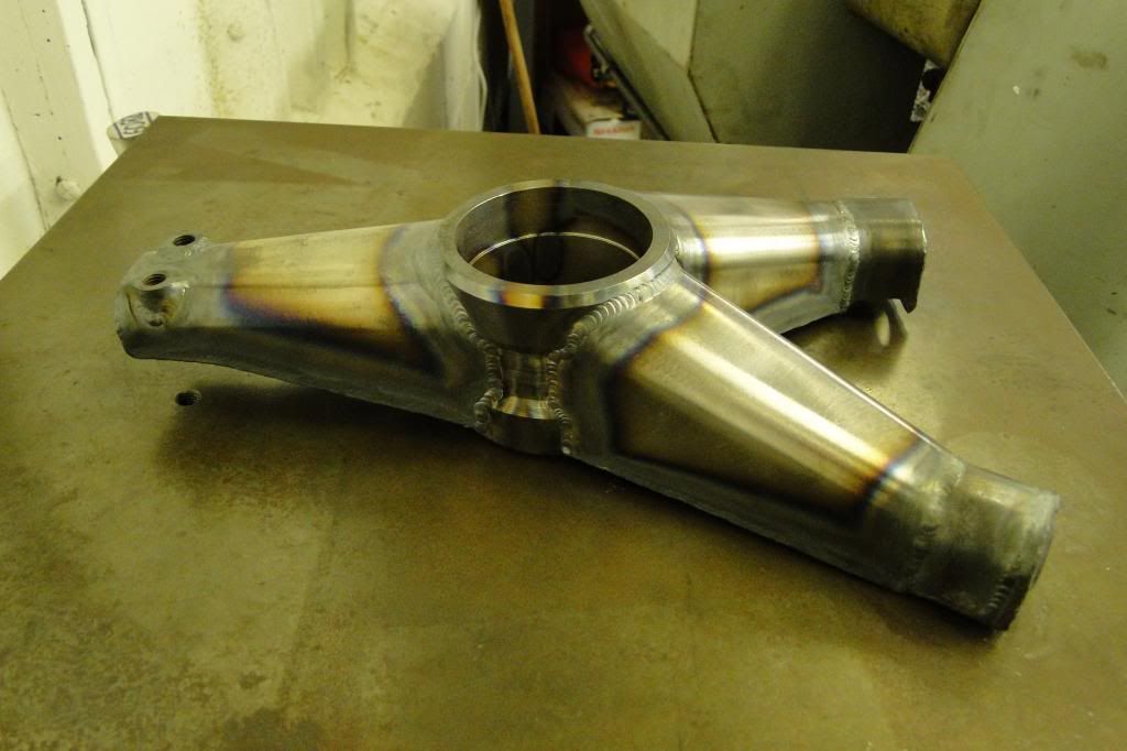

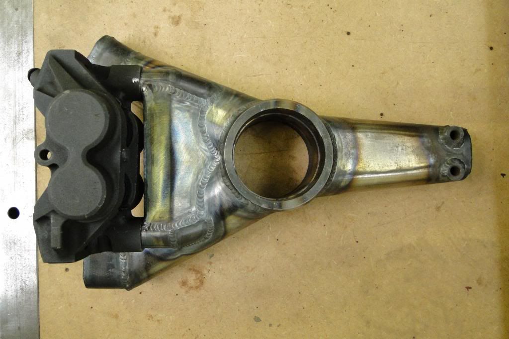
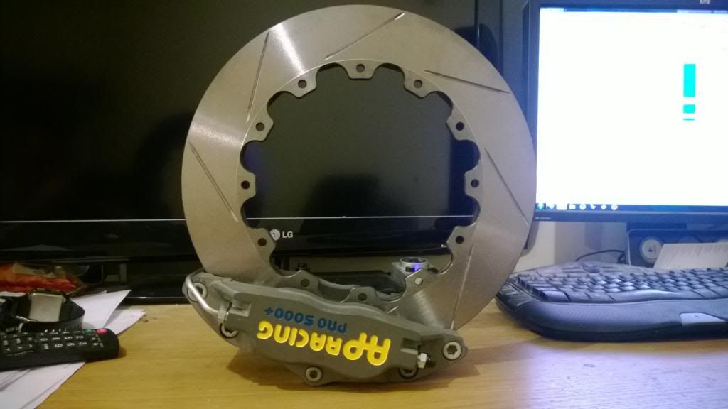
That was the basic structure, so next was making the brake caliper and push-rod mounts. More tasty jig action, and probably my favourite jig so far (<3 jgs) was to hold the caliper bosses in place.
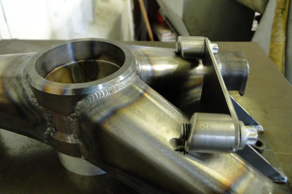
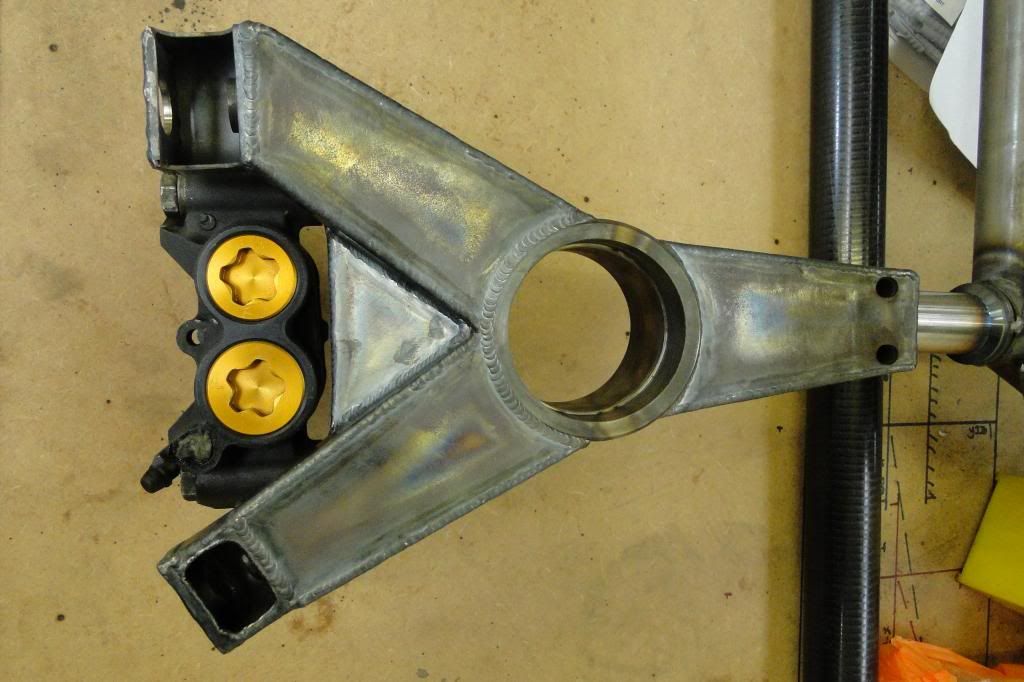
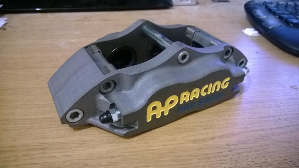
Then, like an excited child, I put the brake caliper on and took some more photos. The calipers are Yamaha R1 monoblocks.. from a 2004 bike I think. I think the pimp-spec gold caps should go well with the rest of the colour scheme!
I turned the various bosses & spacers myself to save a bit of cash..
Since I didn't have a fly press or any other "proper" forming tools, I got creative with some bar stock and RHS to make a little tool I could use in the vice to form the curved edges. I picked up an old surface plate off eGay that I used as a jig table, and made a few fixtures up to hold everything in place for welding.
Then I could start forming the "legs" and welding the bits together.
That was the basic structure, so next was making the brake caliper and push-rod mounts. More tasty jig action, and probably my favourite jig so far (<3 jgs) was to hold the caliper bosses in place.
Then, like an excited child, I put the brake caliper on and took some more photos. The calipers are Yamaha R1 monoblocks.. from a 2004 bike I think. I think the pimp-spec gold caps should go well with the rest of the colour scheme!
Aha, Ian! I thought it might be you from the Manta name.. Yeah I miss that old 205, but it had to go to make way for this build. It was so ratty as I wasn't really worried so much about how it looked as long as it went well.. a student loan can only go so far! Haha. I'm hoping this will be much, much tidier!
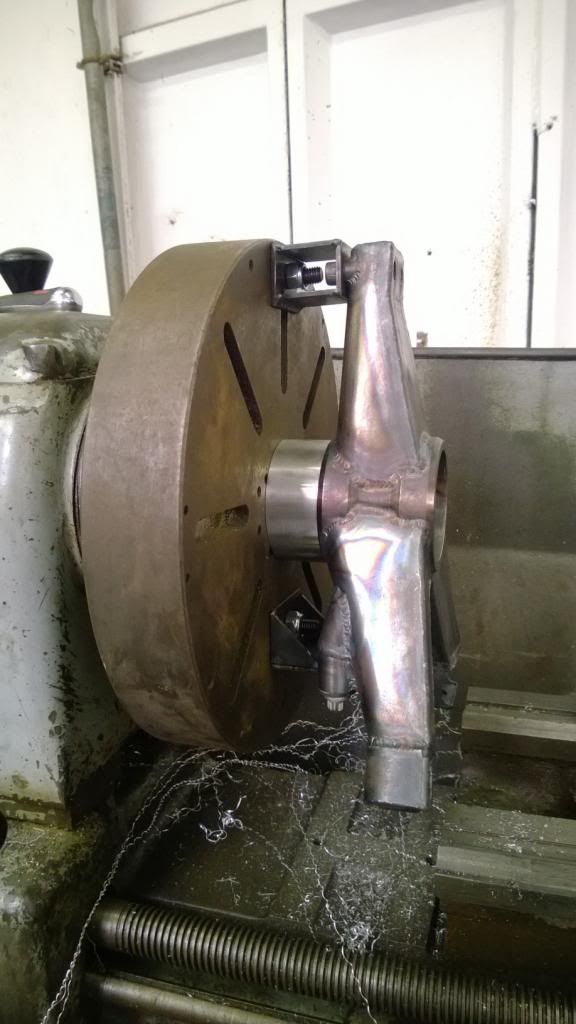
The last thing for those uprights was to machine out the bearing surfaces to take care of any warping (I'd had them machined 4mm undersize). It was pretty fiddly to set up, but worth taking my time on as the two surfaces need to be absolutely concentric! I made up a few fixture to locate it on the surface plate then bored them out.
Then finally welded on the push-rod mounts and they were ready for powder coating.
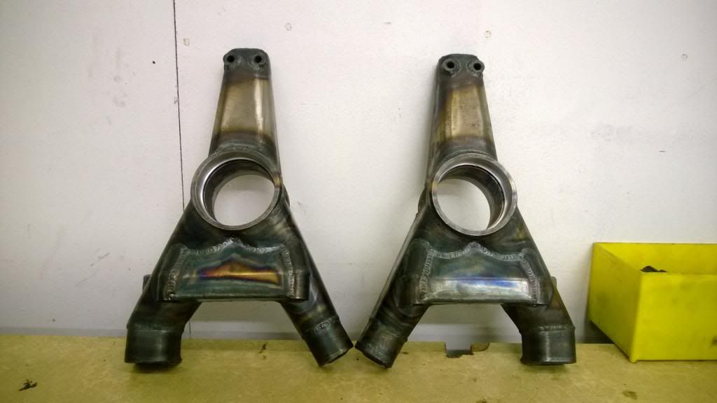
Then finally welded on the push-rod mounts and they were ready for powder coating.
This will bring the project up to date..
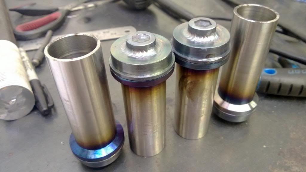
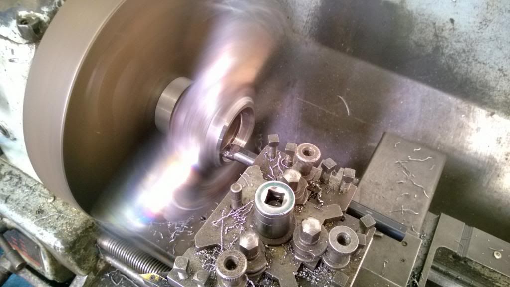
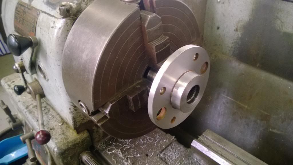
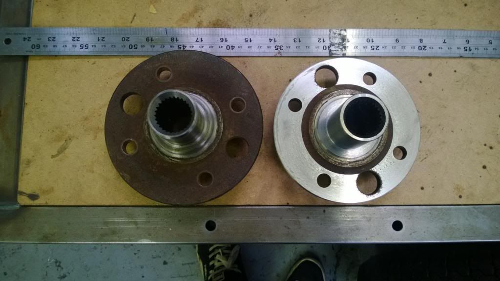
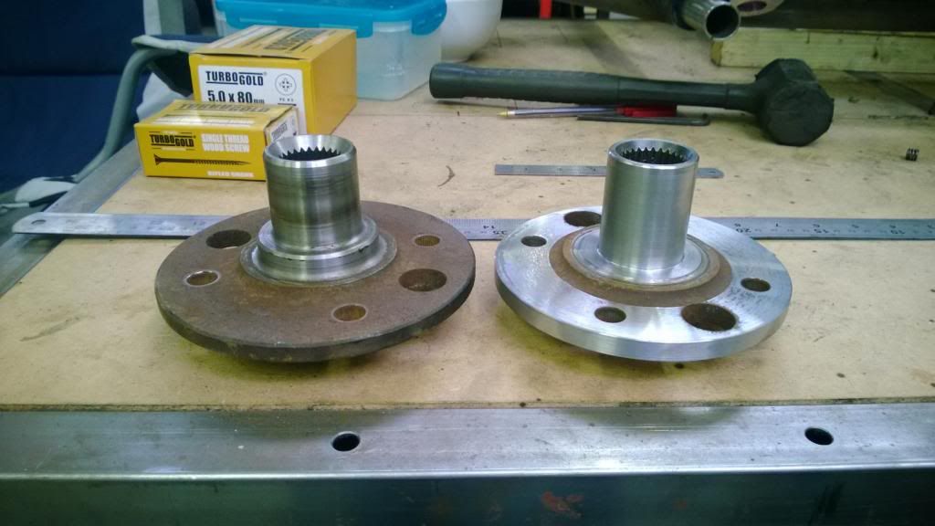
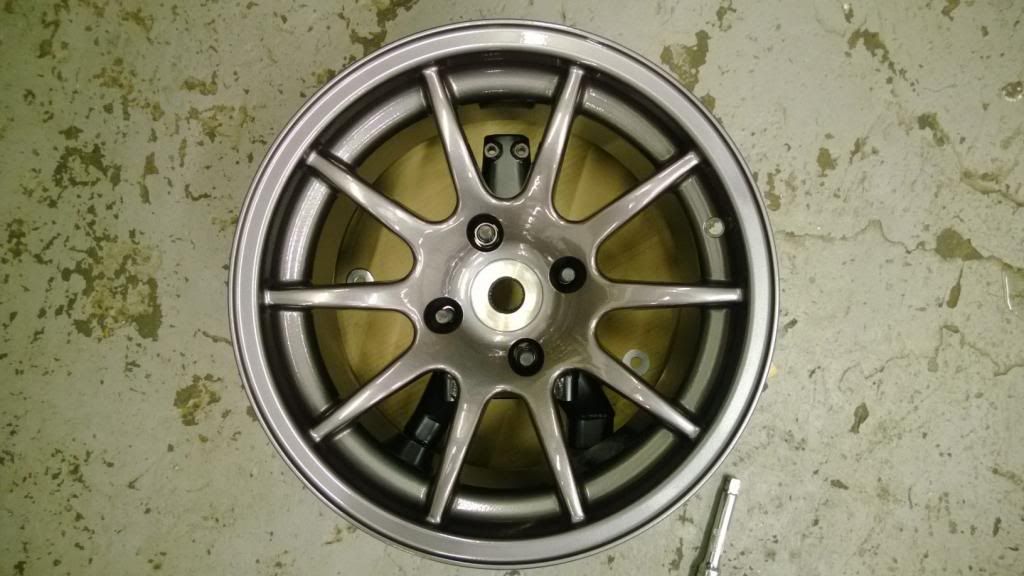
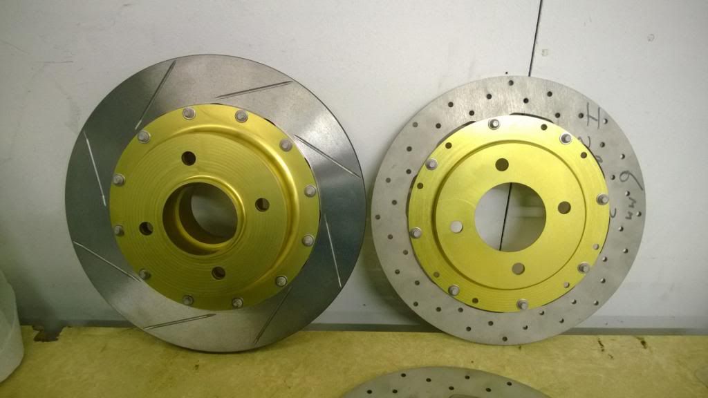
The last thing I did was to machine down the rear hubs. They started off as Sierra parts, but needed to have the faces skimmed and the diameter turned down as it was pretty large. I then flipped the things round and machined the spindle down to extend it's length slightly and reduce the OD from 41mm to 40mm so that it would fit the wheel bearings.
You can see the difference in these pics:
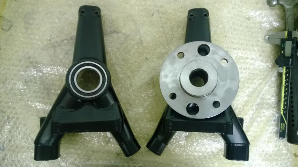
Then, once I'd got all the bits back from powder coating, I pressed in the wheel bearings and assembled the hubs to check everything fits.
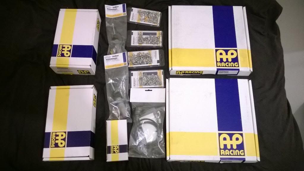
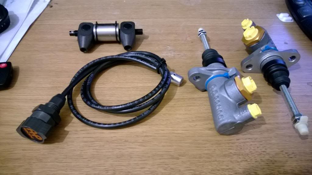
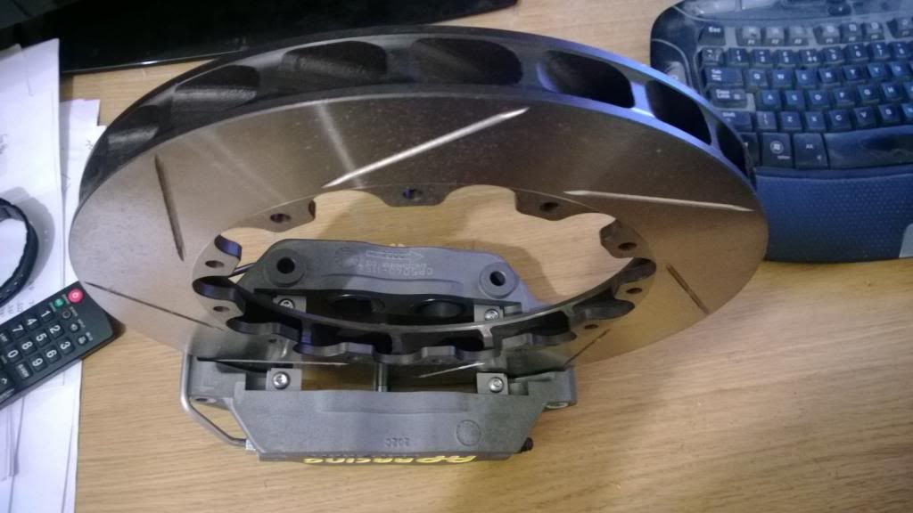
Then, finally, I'll leave you with some pics of my brakes, as everyone likes perving over brakes.
That's pretty much your lot for now! I'm currently waiting for a load of CNC bits to come back so that I can start getting the thing on it's wheels. Once that happens, it'll be powertrain and bodywork.
The last thing I did was to machine down the rear hubs. They started off as Sierra parts, but needed to have the faces skimmed and the diameter turned down as it was pretty large. I then flipped the things round and machined the spindle down to extend it's length slightly and reduce the OD from 41mm to 40mm so that it would fit the wheel bearings.
You can see the difference in these pics:
Then, once I'd got all the bits back from powder coating, I pressed in the wheel bearings and assembled the hubs to check everything fits.
Then, finally, I'll leave you with some pics of my brakes, as everyone likes perving over brakes.
That's pretty much your lot for now!
I'm currently waiting for a load of CNC bits to come back so that I can start getting the thing on it's wheels. Once that happens, it'll be powertrain and bodywork. benters said:
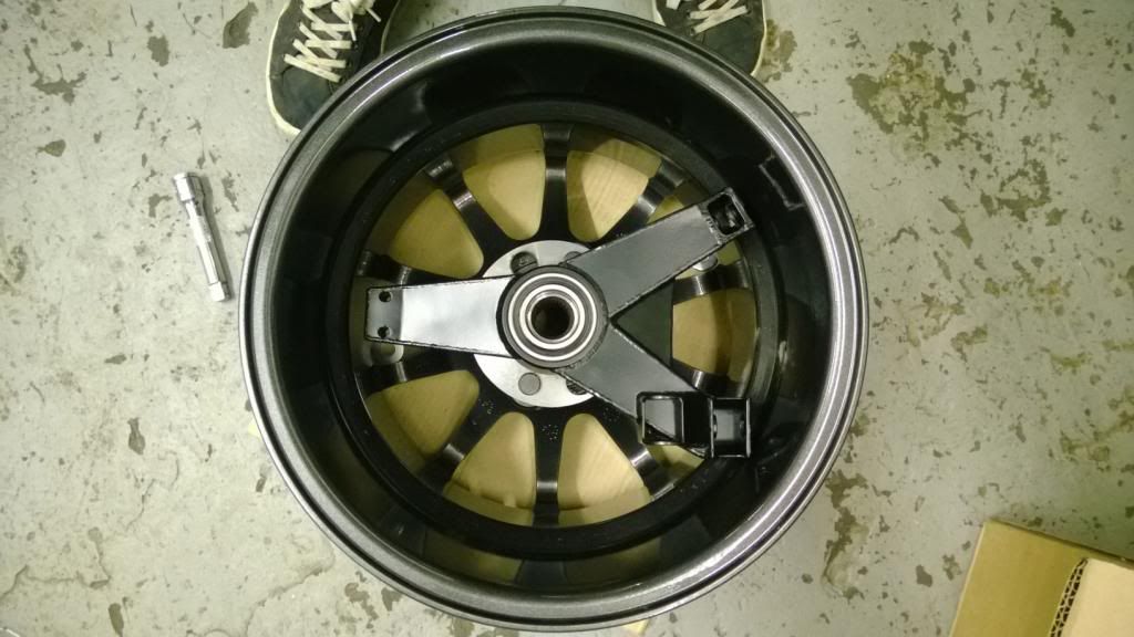
top skills and good pictures to show what your doing too...the action shots of the lathe going are a favourite. The hubs look super close to the wheel rims. . i expect there is plenty of clearance but i kept studying the picture thinking blimey, fag paper between the rim and the upright !
Bookmarked and full of admiration for the project, keep showing me the way ...
There isn't much clearance! In fact, without the brake bell in there the wheel won't go round. Bookmarked and full of admiration for the project, keep showing me the way ...
With the bell on (+6mm) there's only a few mm of clearance.Thanks for the kind words everyone. I did get a few bits back from machining / anodising on Friday, but I'll upload pics when I get the rest as that's when I can start putting them together.
At the moment I'm staying inside where it's warm and doing some CFD. I started off by making a simple model of the 205 body, and have run a few iterations of splitter / diffuser / wing and cooling ducts. I'll stick up a good report on that once things progress a little further; it takes about 8 hours to run each iteration, so will definitely be keeping me busy.
Oh today is a good day!
After a bit (a lot) of a wait I got my parts back from my machinist, and it was definitely worth it. Since I am an impatient child I rushed to the unit after work and checked that everything went together properly, and took some quick pics while I was at it.
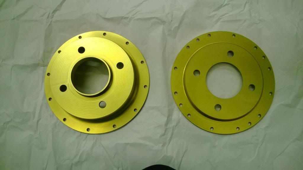
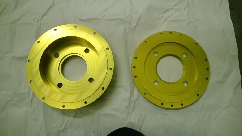
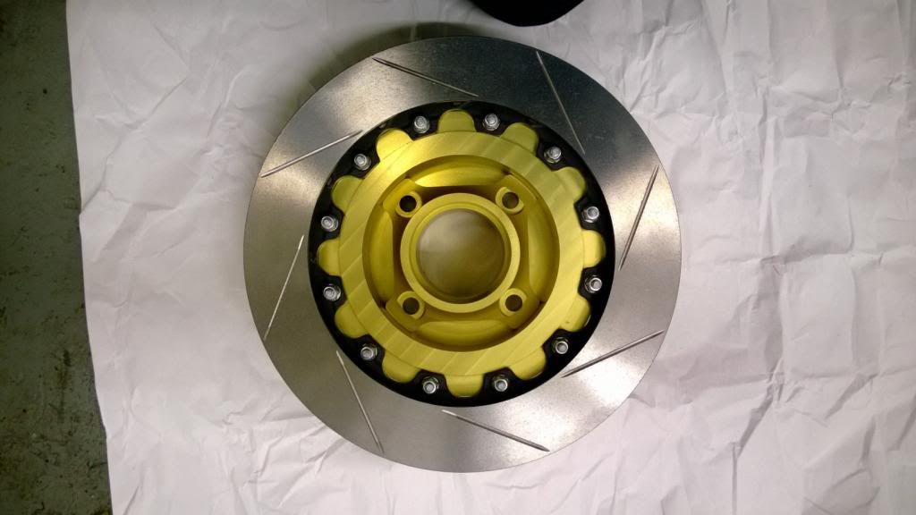
Front & rear disc bells:
Front hubs:
Which fit inside the front bell:
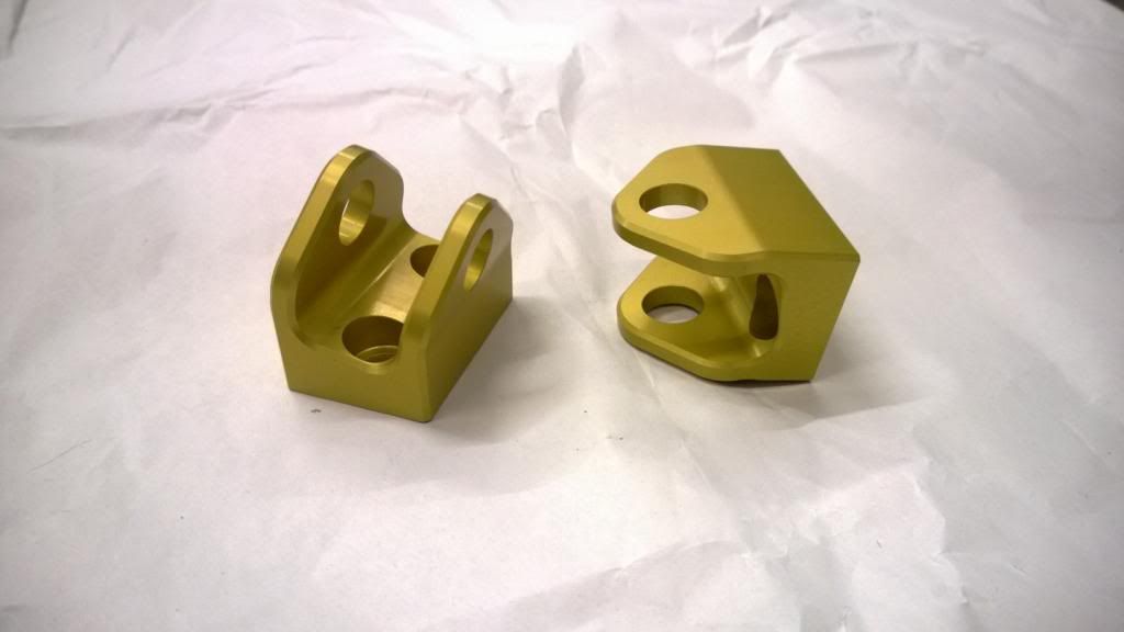
Upper wishbone clevises:
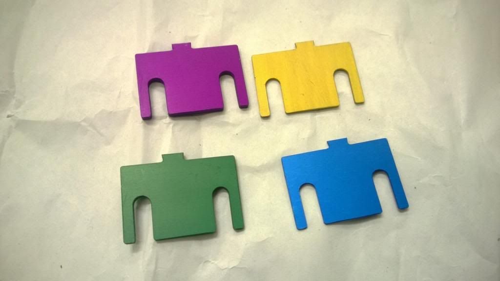
Camber shims - colour coded by thickness:
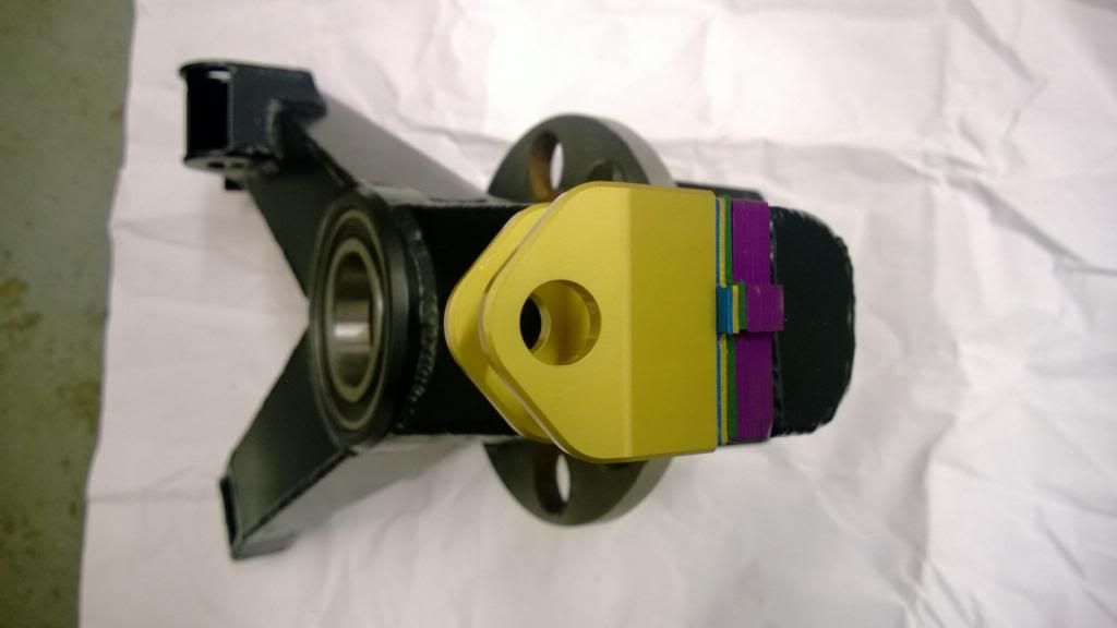
Clevis & upright assembly:
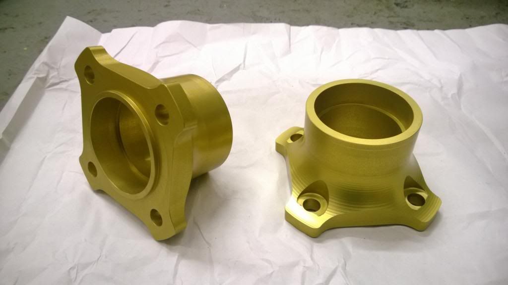
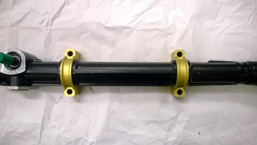
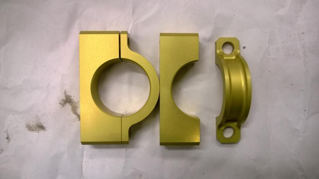
Steering rack mounting blocks:
I'm very happy with all that! I just need to wait for a couple more bits and then I can fit it all to the car and get a glimpse of what it'll look like on it's wheels.
After a bit (a lot) of a wait I got my parts back from my machinist, and it was definitely worth it. Since I am an impatient child I rushed to the unit after work and checked that everything went together properly, and took some quick pics while I was at it.
Front & rear disc bells:
Front hubs:
Which fit inside the front bell:
Upper wishbone clevises:
Camber shims - colour coded by thickness:
Clevis & upright assembly:
Steering rack mounting blocks:
I'm very happy with all that!
I just need to wait for a couple more bits and then I can fit it all to the car and get a glimpse of what it'll look like on it's wheels.Thanks guys. I still can't believe how light the front brake disc assemblies are! It's pretty weird to hold them in your hand, they're a 300mm rotor so you naturally expect them to be quite heavy.
The Mini pickup is Andy's project. I think his plan is to turn it in to a burger van. He's 6' 2".
I still can't believe how light the front brake disc assemblies are! It's pretty weird to hold them in your hand, they're a 300mm rotor so you naturally expect them to be quite heavy. The Mini pickup is Andy's project. I think his plan is to turn it in to a burger van. He's 6' 2".
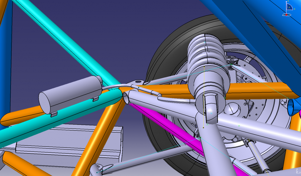
Well.. arses. After a good day spent welding up the rear end of the chassis and sorting the diff mounts, I figured I'd try a nice easy job and try the brakes & wheels on the rear uprights. It turns out that I didn't model the bleed nipple when I made CAD models of the R1 calipers, and it fouls on the inside of the wheel rim to the extent that it being where it is currently on the caliper is impossible. What a f***ing silly mistake!
I think I'll have to relocate the nipple somewhere, somehow. Not quite sure how I'll do that yet.. but maybe I could get new piston bore cap made up that has the bleed nipple inside it and block off the standard location.
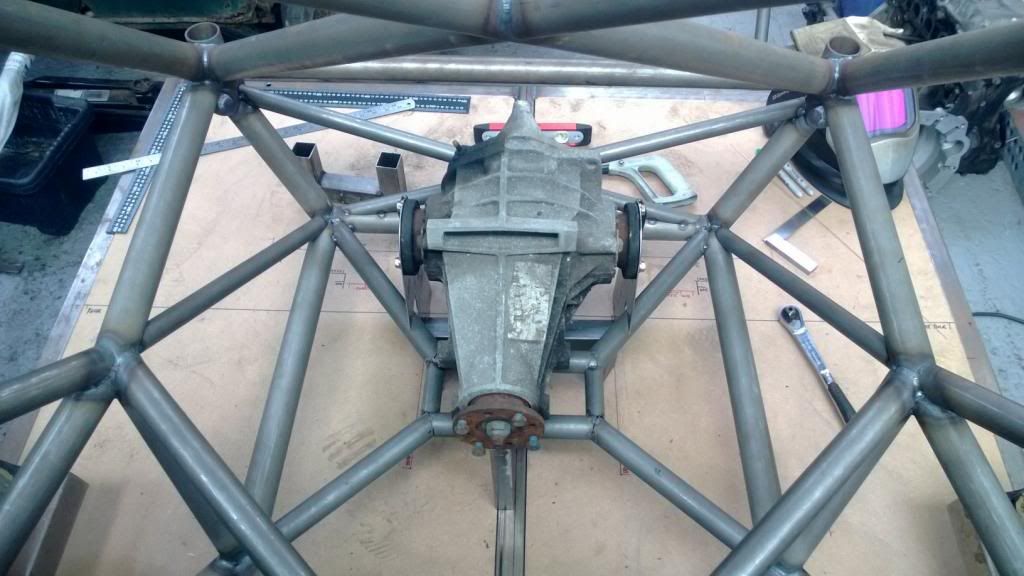
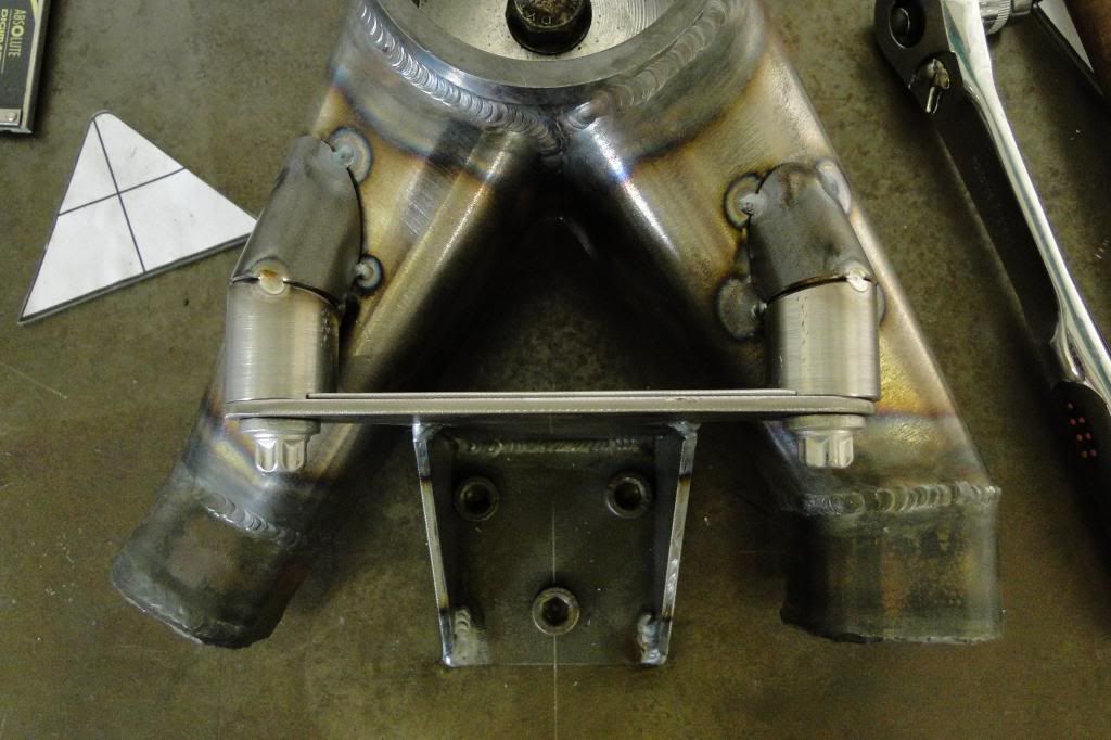
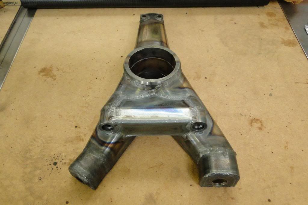
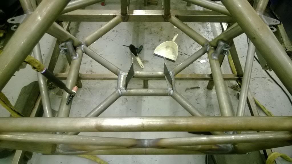
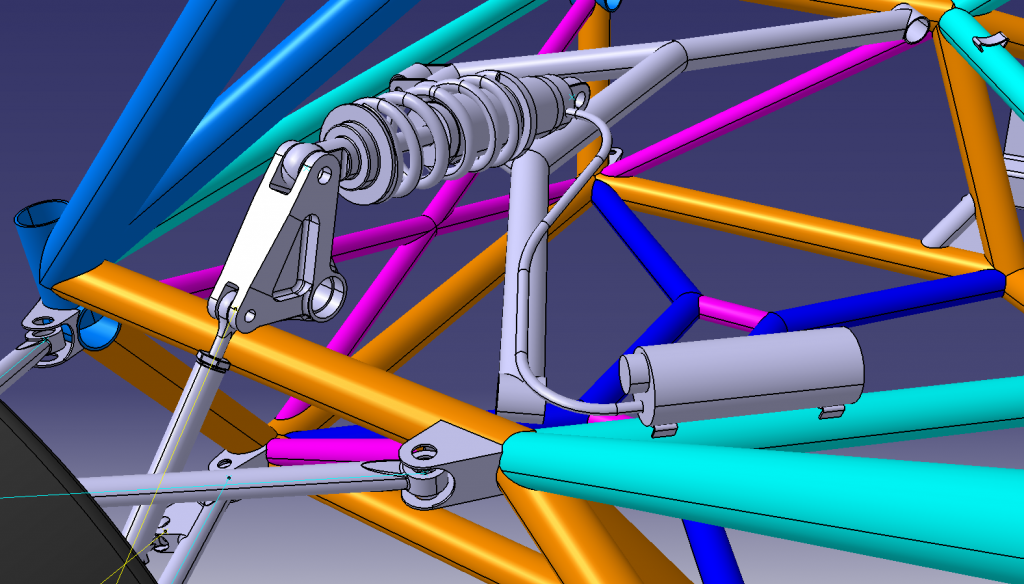
On a positive note, the rear diff mounts, wishbone mounts, and all the extra supporting braces are now fully welded, so the back end is very nearly complete.
I think I'll have to relocate the nipple somewhere, somehow. Not quite sure how I'll do that yet.. but maybe I could get new piston bore cap made up that has the bleed nipple inside it and block off the standard location.
On a positive note, the rear diff mounts, wishbone mounts, and all the extra supporting braces are now fully welded, so the back end is very nearly complete.
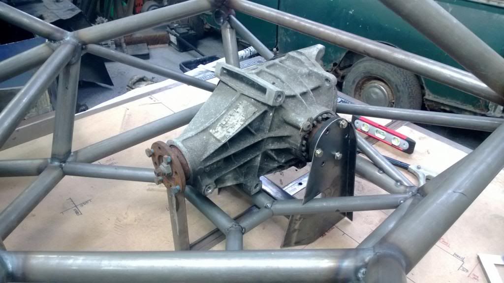
This pics show a problem I had with the first try at the upper diff mount brace.. it turned out to be nigh-on impossible to get the diff out without scratching / scraping the hell out of the frame, so I had to think of something else. Fortunately I'd only tacked it in, so chopped it back out again and will make it removable so the diff can be easily lifted out through the top.
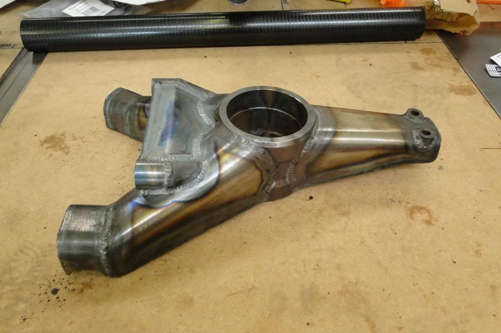
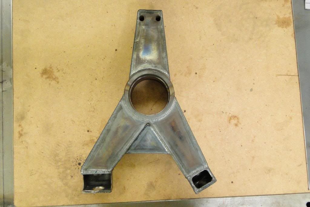
The brace chopped out, and all the rear end welding complete.
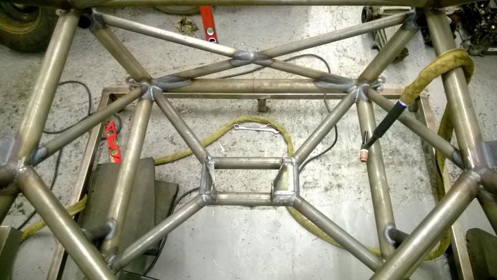
I've just about run out of gas, so no more work this weekend.
The brace chopped out, and all the rear end welding complete.
I've just about run out of gas, so no more work this weekend.
Gassing Station | Readers' Cars | Top of Page | What's New | My Stuff