Half the car is dead :-(
Discussion


So I have a strange scenario where after my recent fusebox self implosion that now half the car (the part that drives it largely) refuses to work and the starter motor is stuck on so wondered if anyone had ideas as to where to look next?
What does work (basically all the bits that should work with the car turned off):
- Alarm enable / disable with indicators flashing and beeps
- Head lights
- Hazard lights
- Horn
- Boot lock when Door ECU connected (you can hear the solenoid shut when the alarm arms)
What doesn't work
- Fuel pump
- Radio
- Indicators
- Doors
- Windows
- Heaters
What runs all the time
- Starter motor
My fusebox is one of those that has no fuse in position 13, and when I did accidentally put one in there as I thought that might be the problem, on enabling the car the starter motor runs continuously but no fuel pump, so luckily the car doesn't try and drive itself!
I checked an older photo and my car should have a 20 Amp fuse at position 13 so I have re-added one and now the starter motor just runs continually
My next plan is to test every fuse, but just wondered from experience if others have gone through similar troubles and if so where best to look? The alarm potentially?
I've just tested every fuse and a 15 Amp at position 7 was blown so I replace that but it hasn't made any difference
Many thanks Alex
What does work (basically all the bits that should work with the car turned off):
- Alarm enable / disable with indicators flashing and beeps
- Head lights
- Hazard lights
- Horn
- Boot lock when Door ECU connected (you can hear the solenoid shut when the alarm arms)
What doesn't work
- Fuel pump
- Radio
- Indicators
- Doors
- Windows
- Heaters
What runs all the time
- Starter motor
I checked an older photo and my car should have a 20 Amp fuse at position 13 so I have re-added one and now the starter motor just runs continually
I've just tested every fuse and a 15 Amp at position 7 was blown so I replace that but it hasn't made any difference
Many thanks Alex
Edited by Juddder on Wednesday 10th November 14:29
Edited by Juddder on Wednesday 10th November 14:43
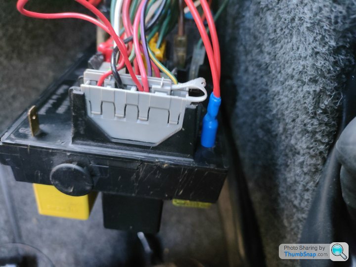
So I managed to get an auto-electrician to look at the fuse box today and it turns out that I had connected the single red wire that had fallen off the back of the fuse box when it fell into the wheel arch to the wrong connector on the fusebox
On the photo below I had it connected to the blade connector on the left labelled 'S' whereas the electrician noticed that the bottom blade connector that it is now connected to had live power, so his suggestion was to move the wire to that connector instead, and when we did this we made progress.
So with the wire correctly connected, the starter motor no longer continually runs and the steering wheel start / stop buttons work correctly and we can start and get the car running, which is great progress
However I still have no doors or windows, and the left indicator flashes continually and the washer pump runs during startup so there are still more gremlins to investigate!
I'm thinking of buying a spare Indicator Control Unit from one of the usual sources to test this out to see if it helps, and maybe sending the door ECU off to get it repaired - I think HF Solutions used to be the place to send them to?
Byker28i said:
Hopefully you haven't blown anything. Now you've got things working, have you tried disconnecting the door control box, leave it a bit and reconnect just to reset things? Last time I changed the battery I had to reset mine, then reset it again because the windows wouldn't wind up etc.
Thanks for the advice and the support and yes definitely much better to have a driveable car that at least I can then fix the other gremlins with!Out of interest for my future self I found this post from 2006 which also talks about the strange behaviour where the starter motor engages continually - in their case it was from removing a fuse but I'm guessing the wire had disconnected is part of the same circuit to have had the same effect

"There are several different fuse boxes out there in Cerberas.
One of the fuses on ours, if removed, just starts the starter motor over and over and over and over... we thankfully found out with the car in neutral!
Someones already mentioned my personal fave fuse... the one which connects the radio, drivers door lock, boot lock (handy), hazards, wipers and who knows what else. Fun."
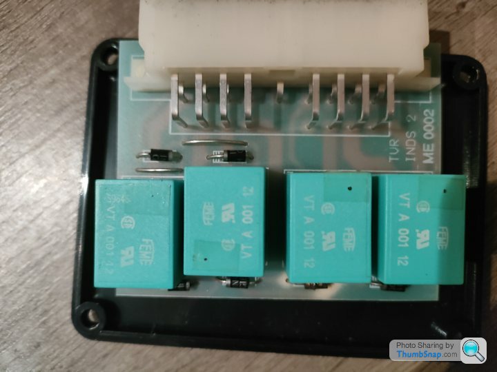
On the doors and windows I have unplugged the door control unit and will leave it like that for a few days and then reconnect it to see if it makes a positive difference
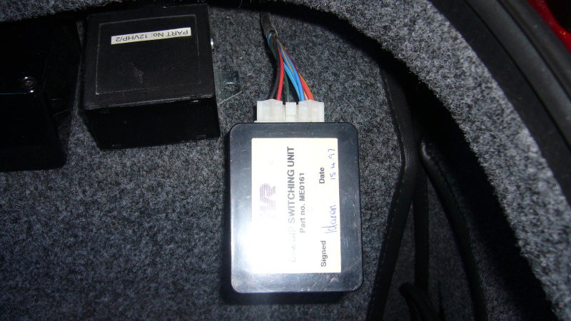
There is also another one of the control boxes - to the right of the door control unit in this photo - that has a loose bottom and corrosion on the bottom of the PCB but isn't labelled so I was thinking of unplugging that and soldering the dry joints - does anyone know what it does before I start?
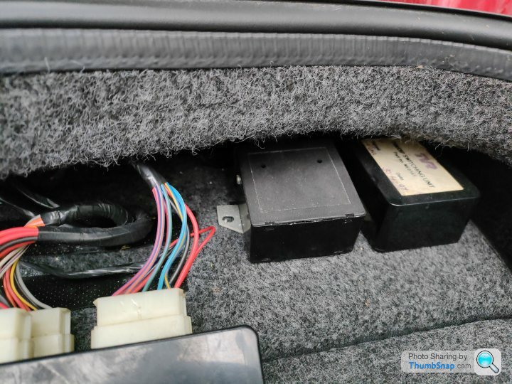
Awesome - thanks for the photos and they'll be really handy for everyone else too 
So I studied the wiring diagrams and found that there are only two units on that that have 6 wire connections - one is the cryptically labelled 'Alarm Accessory' and the other is labelled 'Dim Dip Unit-ECU'
From studying your photo and the colours of the wires it looks like it is the 'Dim Dip Unit-ECU' as the colours are
1 - G (Green)
2 - U/W (Blue with White) [traced from 'Dim Dip Control Unit-ECU']
3 - R (Red)
4 - B (Black)
5 - R/W (Red with White)
6 - R/B (Red with Black) [traced from 'Dim Dip Control Unit-ECU']
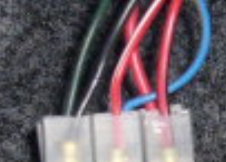
Quite why the car needs two ECU boxes for the dim dip in the lights I have no idea but at least we now know what it is meant to do!
So I studied the wiring diagrams and found that there are only two units on that that have 6 wire connections - one is the cryptically labelled 'Alarm Accessory' and the other is labelled 'Dim Dip Unit-ECU'
From studying your photo and the colours of the wires it looks like it is the 'Dim Dip Unit-ECU' as the colours are
1 - G (Green)
2 - U/W (Blue with White) [traced from 'Dim Dip Control Unit-ECU']
3 - R (Red)
4 - B (Black)
5 - R/W (Red with White)
6 - R/B (Red with Black) [traced from 'Dim Dip Control Unit-ECU']
Quite why the car needs two ECU boxes for the dim dip in the lights I have no idea but at least we now know what it is meant to do!
TwinKam said:
Looks like the power supply only on that plug, so that makes sense...
Good tip and yes it is, it's J46 - as part of my investigation task I've been documenting all of the ECU / Control Box wiring and that plug is just +12V and GndI'll create a new post at the end of this and post them all up - hopefully get it stickied and then it can be a reference for everyone
3. Door Control - ECU
J47 -J48-
J46 J45
(J45) door ECU conn 1
A1 - RH Pin Switch (W/P)
A2 - Lock Switch (S/W)
A3 - RH Inner Switch (O/W)
A4 - LH Inner Switch (O/W)
-
A6 - LH Outer Switch (O)
A7 - RH Outer Switch (O)
A8 - Boot Switch (B/R)
A9 - N/C
B1 - LH Pin Switch (W/P)
B2 - RH Window Position (U/V)
B3 - Alarm Input (K)
B4 - LH Window Position ?
B5 - RH Window Down (Y/G)
B6 - LH Window Up (R/B)
B7 - LH Window Down (R/G)
B8 - RH Window Up (Y/B)
B9 - Road Speed (S)
(J46) door ECU conn 2
A1 - Earth (B)
A2 - N/C
-
A4 - Battery (R)
A5 - N/C
B1 - N/C
B2 - N/C
B3 - N/C
B4 - N/C
B5 - N/C
(J47) door ECU conn 3
A1 - Boot Lock Drive (R/V)
A2 - Battery (R)
-
A4 - Earth (B)
A5 - Battery (R)
B1 - Interior Lamp (P/R)
B2 - RH Lock Drive 1 (U/O)
B3 - RH Lock Drive 2 (U/G)
B4 - LH Lock Drive 1 (U/W)
B5 - LH Lock Drive 2 (U/V)
(J48) door ECU conn 4
[Front]
B1 B2 B3 B4 B5
A1 A2 A4 A5
A1 - Earth (B)
A2 - RH Window 1 (Y/B)
-
A4 - LH Window 1 (R/G)
A5 - Earth (B)
B1 - RH Window 2 (Y/G)
B2 - Battery (R)
B3 - LED Drive
B4 - Battery (R)
B5 - LH Window 2 (R/G)
Penelope Stopit said:
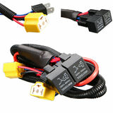
Keeping the above control circuits apart is a good idea as the resistor gets hot
Could be - how did you get on with your replacement circuit?I quite like the idea of putting two of these fused relay boxes in the front wings and removing the rear boxes completely like @RichVr did in this thread or at least disabling the Dim/Dip like @alinton in this thread

Penelope Stopit said:
The following will possibly give you some ideas, I do have a complete working diagram on paper but need some time to draw it
Should you want me to draw and post a full diagram I will gladly do so but will need a little time
Obviously side lights and fog lights circuits need sorting but they're easy
This circuit allows the removing and throwing away of all the light control units
Looks good and the latching relay for the full beam button is nice. re: circuit yes would be interested and thanks for the circuit aboveShould you want me to draw and post a full diagram I will gladly do so but will need a little time
Obviously side lights and fog lights circuits need sorting but they're easy
This circuit allows the removing and throwing away of all the light control units
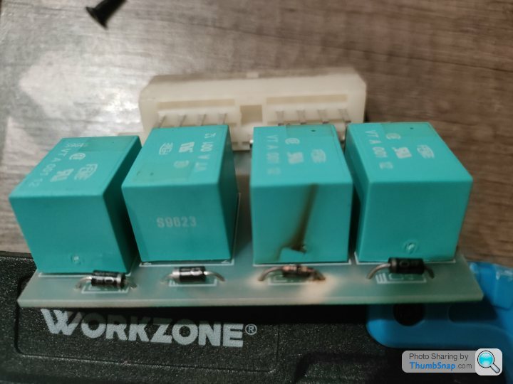
On further investigation today I'm pretty sure I found out the reason my left indicator was stuck flashing

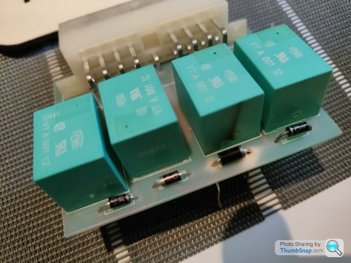
Looks like these are diodes that protect each of the 4 miniature 12V relays (feme vt a 001 12) in the indicator and hazards control box and one of them got friend when the fusebox fell - probably due to grounding or similar I would guess
I'm planning on unsoldering it and replacing it with a IN5817 diode which I have a few hanging around of - 3 lines on the circuit board indicate cathode so I can confirm the polarity even though it's fried

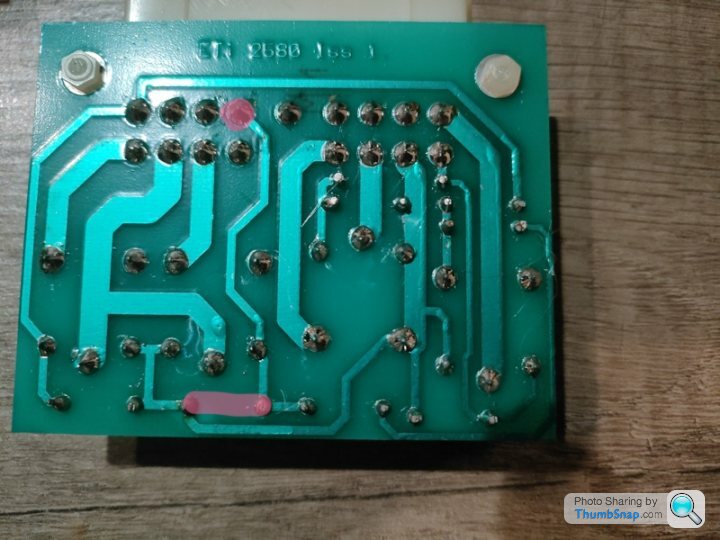
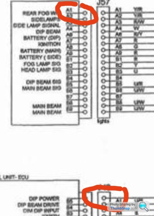
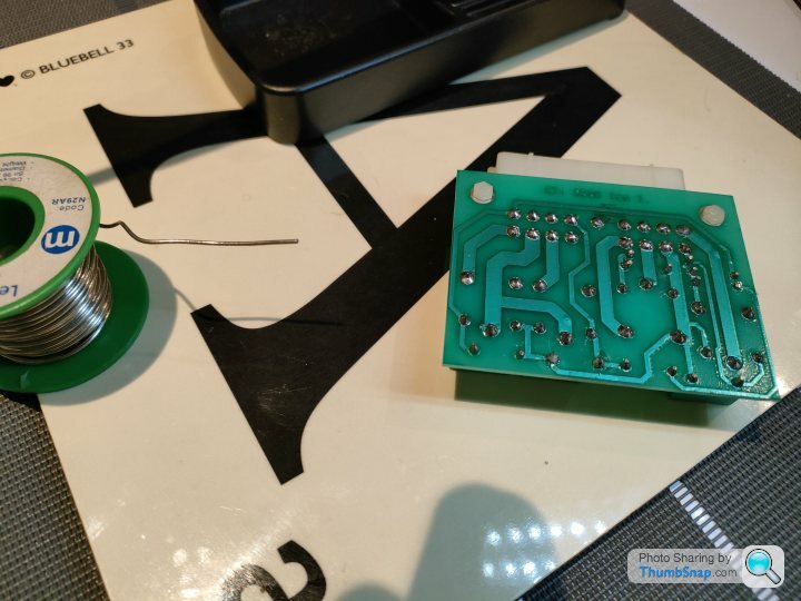
and this shot of the circuit board layout confirms that - the diode in question is connected to pin B4 which is the LH Turn Signal
1. Indicator ECU (J55)
--------------------------------
| A1 A2 A3 A4 | | A6 A7 A8 A9 |
B1 B2 B3 B4 | B5 | B6 B7 B8 B9
------------------------------
A1 - RH Indicators (G/W)
A2 - Flasher Input (LTG/N)
A3 - LH Indicators (O/R)
A4 - N/C
-
A6 - Ignition (G)
A7 - Flash Power (G/Y)
A8 - Battery (R)
A9 - Hazard Signal (N/B)
B1 - RH Turn Signal (G/W)
B2 - N/C
B3 - N/C
B4 - LH Turn Signal (G/R)
B5 - N/C
B6 - N/C
B7 - N/C
B8 - N/C
B9 - Earth (B)
Byker28i said:
There's some really good pin outs etc coming out on this thread
Thanks - it's actually quite therapeutic documenting everything as you go, and seeing as I _have_ to as the car imploded it's electrics, I might as well share everything as I go The TVR site isn't mine - I have the alternative parts list summary - but yes I will definitely post up a sticky post of all of the pinouts and diagrams when this is finished as it will be a good reference for everyone
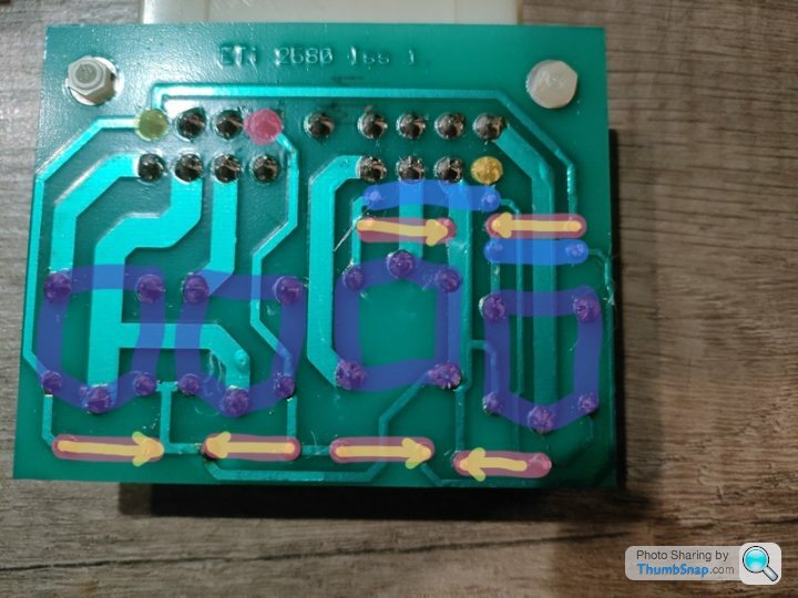
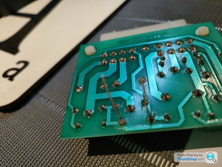
So the indicators and hazards control box is basically made up of 4 micro relays, 6 diodes and some wire jumpers
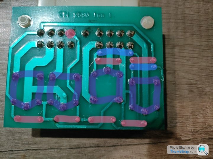
Here's a shot of the bottom of the PCB with the diodes marked in pink, the relays in purple and the wire jumpers in blue - we can easily make a replacement from this as these boards are now pretty much unobtainium
Penelope Stopit said:
Don't know what happened to terminal A5 but it won't cause any problems for this job
Nice A3 or A5 is missing from most of the pinouts on the wiring diagram as it's the key for the connector so has a missing pin
I did similar to you above with the 3 lights related control boxes, so here's the other two for reference too
2.1 Lights ECU (J57)
A1 - Rear Fog W/L (Y/R)
A2 - Rear Fog W/L (Y/R)
A3 - Sidelamps (R/W)
A4 - Side Lamp Signal (W)
-
A6 - Dip Beam (R/Y)
A7 - Battery (Dip) (R)
A8 - Ignition (G)
A9 - Battery (Main) (R)
B1 - Battery (Side) (R)
B2 - Fog Lamp Sig (Y)
B3 - Head Lamp Sig (U)
B4 - N/C
B5 - Dip Beam Sig (U/R)
B6 - Main Beam Sig (U/W)
B7 - N/C
B8 - Main Beam (U/W)
B9 - Main Beam (U/W)
2.2 Dim Dip Control Unit - ECU (J43)
B5 - Dip Power (R/Y) [traced from 'Lights ECU']
B4 - Dip Beam Drive (U/R)
B3 - Dim Dip Input (R/B)
B2 - Earth (B)
B1 - Headlamps On (U/Y)
A5 - Main Beam Signal (U/W)
A4 - Ignition (R)
-
A2 - N/C
A1 - N/C
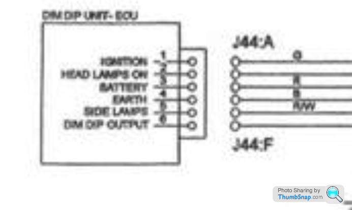
2.3 Dim Dip Unit - ECU (J44-A)
1 - Ignition (G) (Green)
2 - Head Lamps On (U/W) (Blue with White) [traced from 'Dim Dip Control Unit-ECU']
3 - Battery (R) (Red)
4 - Earth (B) (Black)
5 - Side Lamps (R/W) (Red with White)
6 - Dim Dip Output (R/B) (Red with Black) [traced from 'Dim Dip Control Unit-ECU']
Penelope Stopit said:
Forgive me for stealing your work
Steal away and the more we can do for documenting all this stuff the better for everyone 
Here's the whole list I have so far of every box I've read through on the wiring diagrams
[Updated to include Ignition ECU]
1. Indicator ECU (J55)
--------------------------------
| A1 A2 A3 A4 | | A6 A7 A8 A9 |
B1 B2 B3 B4 | B5 | B6 B7 B8 B9
------------------------------
A1 - RH Indicators (G/W)
A2 - Flasher Input (LTG/N)
A3 - LH Indicators (O/R)
A4 - N/C
-
A6 - Ignition (G)
A7 - Flash Power (G/Y)
A8 - Battery (R)
A9 - Hazard Signal (N/B)
B1 - RH Turn Signal (G/W)
B2 - N/C
B3 - N/C
B4 - LH Turn Signal (G/R)
B5 - N/C
B6 - N/C
B7 - N/C
B8 - N/C
B9 - Earth (B)
2.1 Lights ECU (J57)
A1 - Rear Fog W/L (Y/R)
A2 - Rear Fog W/L (Y/R)
A3 - Sidelamps (R/W)
A4 - Side Lamp Signal (W)
-
A6 - Dip Beam (R/Y)
A7 - Battery (Dip) (R)
A8 - Ignition (G)
A9 - Battery (Main) (R)
B1 - Battery (Side) (R)
B2 - Fog Lamp Sig (Y)
B3 - Head Lamp Sig (U)
B4 - N/C
B5 - Dip Beam Sig (U/R)
B6 - Main Beam Sig (U/W)
B7 - N/C
B8 - Main Beam (U/W)
B9 - Main Beam (U/W)
2.2 Dim Dip Control Unit - ECU (J43)
B5 - Dip Power (R/Y) [traced from 'Lights ECU']
B4 - Dip Beam Drive (U/R)
B3 - Dim Dip Input (R/B)
B2 - Earth (B)
B1 - Headlamps On (U/Y)
A5 - Main Beam Signal (U/W)
A4 - Ignition (R)
-
A2 - N/C
A1 - N/C
2.3 Dim Dip Unit - ECU (J44-A)
1 - Ignition (G) (Green)
2 - Head Lamps On (U/W) (Blue with White) [traced from 'Dim Dip Control Unit-ECU']
3 - Battery (R) (Red)
4 - Earth (B) (Black)
5 - Side Lamps (R/W) (Red with White)
6 - Dim Dip Output (R/B) (Red with Black) [traced from 'Dim Dip Control Unit-ECU']
3. Door Control - ECU
J47 -J48-
J46 J45
(J45) door ECU conn 1
A1 - RH Pin Switch (W/P)
A2 - Lock Switch (S/W)
A3 - RH Inner Switch (O/W)
A4 - LH Inner Switch (O/W)
-
A6 - LH Outer Switch (O)
A7 - RH Outer Switch (O)
A8 - Boot Switch (B/R)
A9 - N/C
B1 - LH Pin Switch (W/P)
B2 - RH Window Position (U/V)
B3 - Alarm Input (K)
B4 - LH Window Position ?
B5 - RH Window Down (Y/G)
B6 - LH Window Up (R/B)
B7 - LH Window Down (R/G)
B8 - RH Window Up (Y/B)
B9 - Road Speed (S)
(J46) door ECU conn 2
A1 - Earth (B)
A2 - N/C
-
A4 - Battery (R)
A5 - N/C
B1 - N/C
B2 - N/C
B3 - N/C
B4 - N/C
B5 - N/C
(J47) door ECU conn 3
A1 - Boot Lock Drive (R/V)
A2 - Battery (R)
-
A4 - Earth (B)
A5 - Battery (R)
B1 - Interior Lamp (P/R)
B2 - RH Lock Drive 1 (U/O)
B3 - RH Lock Drive 2 (U/G)
B4 - LH Lock Drive 1 (U/W)
B5 - LH Lock Drive 2 (U/V)
(J48) door ECU conn 4
[Front]
B1 B2 B3 B4 B5
A1 A2 -- A4 A5
A1 - Earth (B)
A2 - RH Window 1 (Y/B)
-
A4 - LH Window 1 (R/G)
A5 - Earth (B)
B1 - RH Window 2 (Y/G)
B2 - Battery (R)
B3 - LED Drive
B4 - Battery (R)
B5 - LH Window 2 (R/G)
4.1 Immobiliser - ECU (J54)
1 - Ignition (G)
2 - Battery (R)
3 - Earth (B)
4 - Ignition ECU (G)
5 - Ignition ECU (G)
6 - Earth (B)
7 - N/C
8 - Starter (W/R) [traced from Ignition ECU B5]
9 - N/C
10 - Starter (W/R)
11 - Fuel Pump (Y)
12 - Fuel Pump (Y)
4.2 Alarm - ECU (J36)
1 - N/C
2 - Door Pin (W/P)
3 - Boot/Bonnet (U/B)
4 - N/C
5 - Alarm State (K)
6 - Earth (B)
7 - N/C
8 - Ignition (G)
9 - LH Indicator (G/R)
10 - N/C
11 - Battery (R)
12 - RH Indicator (G/W)
4.3 Alarm Accessory (J37)
1 - Battery (R) [Alarm ECU 11]
2 - Ignition (G) [Alarm ECU 8]
3 - Earth (B)
4 - Alarm State (K) [traced from Alarm ECU 5]
5 - Door Pin (W/P) [traced from Alarm ECU 2]
6 - N/C
Note: 5 - Door Pin connects to -> diode D1 / diode D2 -> LH Pin Switch [Door Control ECU B1] / RH Pin Switch [Door Control ECU A1] -> J33 [Pin1] / J33 [Pin 7]
5. Ignition ECU (J53)
A1 - Battery (IGN?) (R)
A2 - Ignition Earth (B)
-
A4 - N/C
A5 - Battery (Start) (R)
B1 - Ignition Output (W)
B2 - Start Signal (R/W)
B3 - Stop Signal (?)
B4 - N/C
B5 - Starter Drive (W/?) [Immobiliser ECU 8]
Colour Codes
B - Black
N - Brown
R - Red
O - Orange
Y - Yellow
G - Green
LTG - Light Green
U - Blue
P - Purple
K - Pink
W - White
S - Slate (Grey)
Edited by Juddder on Tuesday 23 November 11:32
Penelope Stopit said:
Updating
Interesting and yes I just double checked A7 the Dim Dip feed and it does indeed go through Fuse 4 according to the wiring diagrams, when the handbook fuse diagram says Fuse 21!So basically
Fuse 21 description = Fuse 4
Fuse 2 description = Fuse 21
Fuse 4 description = Fuse 2
Trace of Fuse 4 below
30b CON-H - J75 (pin 1) - Fuse 4 [along with CON-F - J73 (pin 1)] F 30AL (5 up) -> "Dim Dip Unit" - ECU pin 3 battery
Penelope Stopit said:
This tells us that the correct method for removing Dim Dip is to throw away the Dim Dip Control Unit ECU and Dim Dip Unit ECU then
join the Red/Yellow cable to the Blue/Red cable at the Dim Dip Control Unit ECU plug
Funnily enough I just wrote myself this note on the control box wiring list I am compiling based on two other posts for bypassing the Dim Dip effectjoin the Red/Yellow cable to the Blue/Red cable at the Dim Dip Control Unit ECU plug
Note: There are multiple ways to disable the Dim Dip Control Unit (called the DIM/DIP Switching Unit [ME0161] on the box), either cut wire B3 (the Dim Dip Input) or bridge a diode between A5 (Main Beam Signal) in the direction of B5 (Dip Power) so that 12V is supplied rather than the dipped 9.6V or so
Based on two posts by alinton here and here
Removing the boxes and joining a wire is a much nicer and more maintainable approach
There's also this good post about using the boot relay high current as the low current switch for new relays in the bonnet which is an OK approach too
Edited by Juddder on Wednesday 24th November 18:44
Edited by Juddder on Wednesday 24th November 18:51
[Additional references added to Dim Dip bypass and a bit of formatting]
The Red/Yellow cable [B5 - Dip Power] connected to the Dim Dip Control Unit ECU is important as it supplies +12V (give or take a little) to the Dip Beam Bulbs via the Dim Dip Control Unit ECU to give full brightness dip beams.
When the dim dip circuit is operating, a lower voltage is switched from the Dim Dip Unit ECU to the Dim Dip Control Unit ECU, through it and onwards to the Dip Beam Bulbs
This tells us that the correct method for removing Dim Dip is to throw away the Dim Dip Control Unit ECU and Dim Dip Unit ECU then join the Red/Yellow cable [B5 - Dip Power] to the Blue/Red cable [B4 - Dip Beam Drive] at the Dim Dip Control Unit ECU plug (J43)
Penelope Stopit said:
Purely out of interest
Are you sure the above is correct?
Should
Red/Yellow cable [B5 - Dip Power] to the Blue/Red cable [B4 - Dip Beam Drive] at the Dim Dip Control Unit ECU plug
Read
Red/Yellow cable [J43 A1 - Dip Power] to the Blue/Red cable [J43 A2 - Dip Beam Drive] at the Dim Dip Control Unit ECU plug
Yes I think you're right and to be honest unless we meter these diagrams out then it's going to be difficult to be 100% trusting in themAre you sure the above is correct?
Should
Red/Yellow cable [B5 - Dip Power] to the Blue/Red cable [B4 - Dip Beam Drive] at the Dim Dip Control Unit ECU plug
Read
Red/Yellow cable [J43 A1 - Dip Power] to the Blue/Red cable [J43 A2 - Dip Beam Drive] at the Dim Dip Control Unit ECU plug
I hadn't noticed the upside down numbering on the plug, so I think you are correct that the pin naming should be changed - here's the logic I used to get where I am
1. Photo of the unit
Starting on the top right you can see a Red/Yellow cable and a Blue/Red cable next to it - this matches the wiring diagram if you trace out the top wire back to the Lights ECU as per highlighted below
2. Wire trace
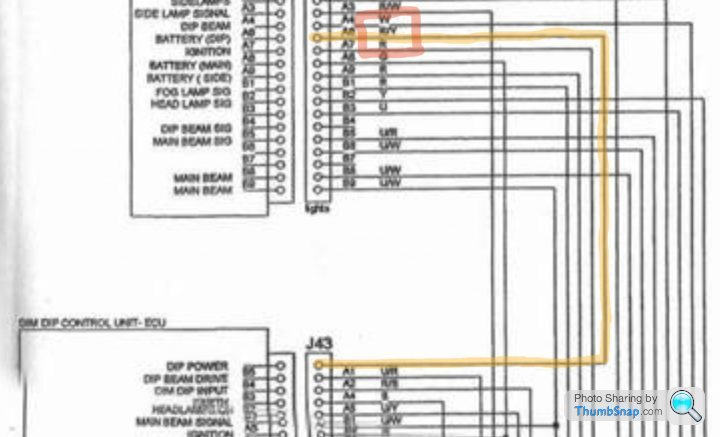
So if we go with the logic that the top left wire as you look at the back of the unit is A1 as per other plugs, then your logic makes sense
 --------------------
| A1 A2 |    | A4 A5 |
  B1 B2 | B3 | B4 B5
  ------------------
Also I think the labelling of the plug on J43 is wrong on both sides.
If you look at the other plugs, A1 is above the first wire as per this screenshot, whereas on J43 they have the second wire labelled as A1 which is incorrect. Also the A row is always used as the key with the middle wire having no pin (I have some of the control units here and have checked that) so A3 should be not populated
This would give us:
2.2 Dim Dip Control Unit - ECU (J43)
A1 - Dip Power (R/Y) [traced from 'Lights ECU']
A2 - Dip Beam Drive (U/R)
-
A4 - Dim Dip Input (R/B)
A5 - Earth (B)
B1 - Headlamps On (U/Y)
B2 - Main Beam Signal (U/W)
B3 - Ignition (R)
B4 - N/C
B5 - N/C
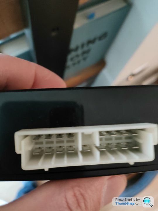
If you look at the other plugs, A1 is above the first wire as per this screenshot, whereas on J43 they have the second wire labelled as A1 which is incorrect. Also the A row is always used as the key with the middle wire having no pin (I have some of the control units here and have checked that) so A3 should be not populated
This would give us:
2.2 Dim Dip Control Unit - ECU (J43)
 --------------------
| A1 A2 |    | A4 A5 |
  B1 B2 | B3 | B4 B5
  ------------------
A1 - Dip Power (R/Y) [traced from 'Lights ECU']
A2 - Dip Beam Drive (U/R)
-
A4 - Dim Dip Input (R/B)
A5 - Earth (B)
B1 - Headlamps On (U/Y)
B2 - Main Beam Signal (U/W)
B3 - Ignition (R)
B4 - N/C
B5 - N/C
So the 12V diodes for fixing the Indicator & Hazard Lamps Switching Unit have arrived so I soldered that in place and documented the flow of the current that this makes on the PCB and thus the relays
The low current inputs are highlighted with dots below:
B1 - RH Turn Signal (G/W) (green)
B4 - LH Turn Signal (G/R) (pink)
A9 - Hazard Signal (N/B) (yellow)
Diodes have arrived
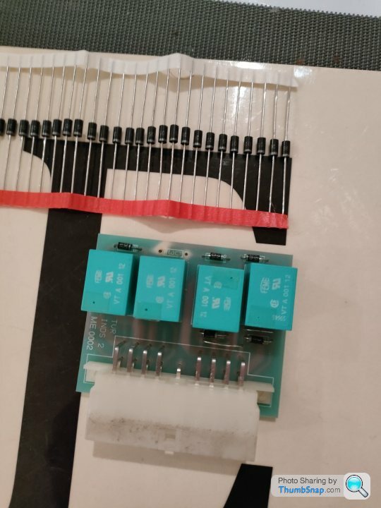
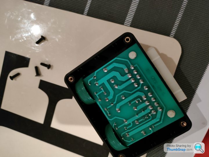
Soldered in place
Continuity tested with a multimeter and extra legs trimmed - all tests fine on connections with junctions either side
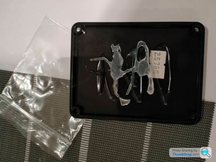
Last thing to fix is that the factory used liberal amounts of glue to hold the boards in place as they are smaller than the boxes they are in. It's pretty ugly and not something that I wanted to do, so my good old solution of 2 litre water bottle tops came to the rescue
The low current inputs are highlighted with dots below:
B1 - RH Turn Signal (G/W) (green)
B4 - LH Turn Signal (G/R) (pink)
A9 - Hazard Signal (N/B) (yellow)
Diodes have arrived
Soldered in place
Continuity tested with a multimeter and extra legs trimmed - all tests fine on connections with junctions either side
Last thing to fix is that the factory used liberal amounts of glue to hold the boards in place as they are smaller than the boxes they are in. It's pretty ugly and not something that I wanted to do, so my good old solution of 2 litre water bottle tops came to the rescue
Penelope Stopit said:
Anyway, It's been a pleasure working through the diagrams with you
Will post some more diagrams shortly
Thanks and yes it is very satisfying to work this through and bounce ideas backwards and forwards so definitely vice verse Will post some more diagrams shortly
I think when we have the working replacement circuit we should give it to some of the cerbera website guys to host, and maybe start a separate sticky thread so that it's available for everyone rather having to read through our explorations
Byker28i said:
And yes, a hot glue gun tends to be an essential tool when working on TVR electrics and control boxes 
Thanks I'm going to be looking at the Door / Window Control Box later on today which from an initial opening is a two layer board with some ribbon cable connecting the two boards together
Anyone ever worked on one of these before and are there common areas of the board where they go wrong that I should focus on?
I'm hoping it's another blown diode or similar from when the fusebox imploded and obviously by the electrical effect to the Indicator Box shorted itself somehow
Gassing Station | Cerbera | Top of Page | What's New | My Stuff