Kawasaki GT550 rebuild
Discussion


This thread will record the rebuild of my 1993 Kawasaki GT550 G9. I bought the GT550 in November 2010 as a cheap way to see if commuting to the office by bike would be successful. The last time I had owned a bike was in 1982 so a low powered middleweight seemed the right way to go. I also thought that any financial loss would be small since the Kawasaki had 6 months tax and MOT and its parts value was not much less than the price I paid.
Using the bike for work proved to be a great success and the GT550 was also very reliable. I gradually improved various parts of it - new seat cover, rusty areas repainted, general servicing - and decided to keep it. One interesting issue did arise. When I bought the bike it ran well at low revs but was reluctant to reach the redline. This did not bother me too much given the daily commuting. After a month of use I decided to check the valve clearances and re-shim if necessary. I took the rocker cover off then decided I should check the vale timing marks so that I would know what to achieve on re-assembly. The manual made clear the marks were on the right-hand side of the cam sprockets but on my bike they were absent. After some thought about what to do I checked the left-hand side of the sprockets - and there were the timing marks. At some point in the bkies life the camshafts had been installed running the wrong way across the head. So, the valves were opened be the closing side of the lobes and closed by the opening side. There was also no way of telling (without measuring) what this was doing to the valve timing. I still do not understand how anyone who was capable of such a basic error could actually ensure the valves were timed so that the bike would run. Perhaps is was just luck. Anyway, once the cams were installed correctly the bike had no problem pulling cleanly to the redline.
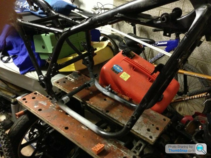
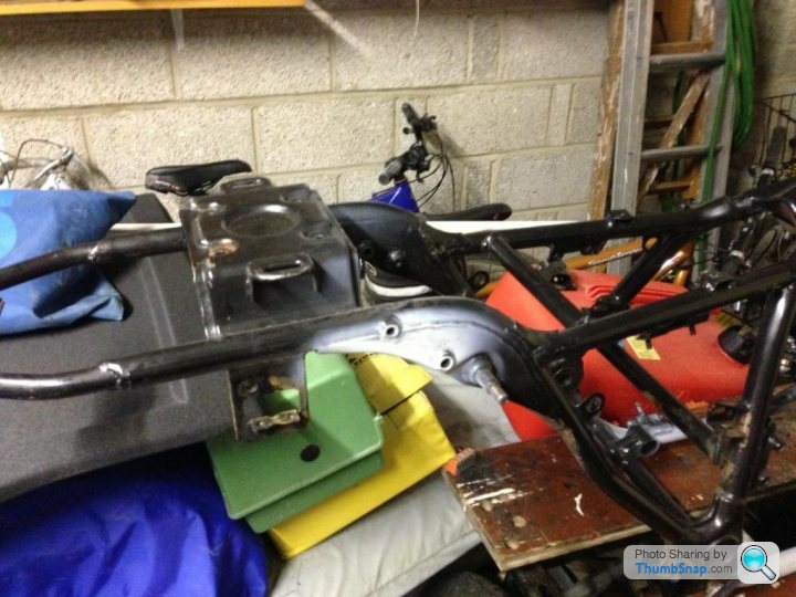
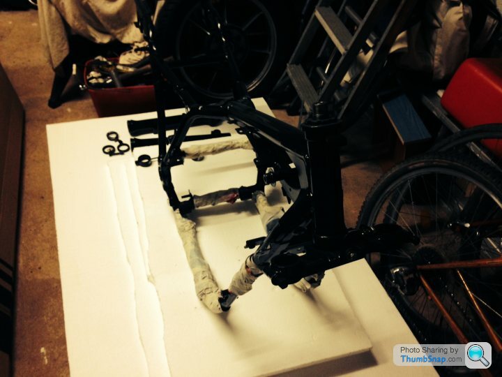
In March this year I noticed some rust on the lower tubes of the frame. Closer inspection revealead several small holes and the beginnings of a crack. This gave me no choice but to take the bike off the road and begin dismantling. This was completed in June. I then cleaned the frame and found three areas of significant damage. I thought about repairing myself but my welding is just not good enough. Two weeks ago I finally took the frame for professional repair. The grey primer in the pictures shows where the repairs have been made. Both lower tubes and one of the upper shock mounts have had new metal inserted.
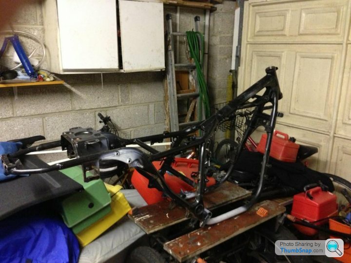
The plan now is to strip the frame of all paint, neutralise the surface rust, and then re-paint. I have considered powder coating but prefer a traditional paint finish. The project will last several months as I also plan to rebuild the engine. This has an oil leak from the joint between the base of the barrel and the crankcase. It also seems worth replacing the cam chain while the engine is out fo the frame.
Using the bike for work proved to be a great success and the GT550 was also very reliable. I gradually improved various parts of it - new seat cover, rusty areas repainted, general servicing - and decided to keep it. One interesting issue did arise. When I bought the bike it ran well at low revs but was reluctant to reach the redline. This did not bother me too much given the daily commuting. After a month of use I decided to check the valve clearances and re-shim if necessary. I took the rocker cover off then decided I should check the vale timing marks so that I would know what to achieve on re-assembly. The manual made clear the marks were on the right-hand side of the cam sprockets but on my bike they were absent. After some thought about what to do I checked the left-hand side of the sprockets - and there were the timing marks. At some point in the bkies life the camshafts had been installed running the wrong way across the head. So, the valves were opened be the closing side of the lobes and closed by the opening side. There was also no way of telling (without measuring) what this was doing to the valve timing. I still do not understand how anyone who was capable of such a basic error could actually ensure the valves were timed so that the bike would run. Perhaps is was just luck. Anyway, once the cams were installed correctly the bike had no problem pulling cleanly to the redline.
In March this year I noticed some rust on the lower tubes of the frame. Closer inspection revealead several small holes and the beginnings of a crack. This gave me no choice but to take the bike off the road and begin dismantling. This was completed in June. I then cleaned the frame and found three areas of significant damage. I thought about repairing myself but my welding is just not good enough. Two weeks ago I finally took the frame for professional repair. The grey primer in the pictures shows where the repairs have been made. Both lower tubes and one of the upper shock mounts have had new metal inserted.
The plan now is to strip the frame of all paint, neutralise the surface rust, and then re-paint. I have considered powder coating but prefer a traditional paint finish. The project will last several months as I also plan to rebuild the engine. This has an oil leak from the joint between the base of the barrel and the crankcase. It also seems worth replacing the cam chain while the engine is out fo the frame.
I started this thread many months ago expecting to quickly add updates. I discovered that it takes a very long time to strip the paint off a frame and to remove twenty years of accumulated grime and rust. The frame was eventually sanded to bare metal and treated with Loctite rust stabilizer. It was then finished with acrylic primer and top coat. 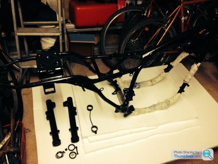
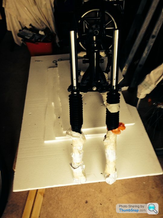
The tape is to protect the painted frame in storage and when the engine is lifted in. The forks were stripped to paint the lower legs and to fit new fork oil seals. The copper washers and the plastic washeres were all renewed. The thin pipe in the picture is to balance the air pressure between the fork legs.
The tape is to protect the painted frame in storage and when the engine is lifted in. The forks were stripped to paint the lower legs and to fit new fork oil seals. The copper washers and the plastic washeres were all renewed. The thin pipe in the picture is to balance the air pressure between the fork legs.
The bottom fork holder/bottom bracket was cleaned and refitted. The original steering head bearings were fine so were cleaned and re-used. The bolts for the headlight support were replaced with stainless steel.
The forks were rebuilt, pushed loosely into place, and covered for protection. Their position will be finalised when the top for holder and handlebars are trial fitted. The masking tape on the gaiter has a message reminding me to check the tightness of the fork cylinder bolts.
The forks were rebuilt, pushed loosely into place, and covered for protection. Their position will be finalised when the top for holder and handlebars are trial fitted. The masking tape on the gaiter has a message reminding me to check the tightness of the fork cylinder bolts.
Gareth9702 said:
I discovered that it takes a very long time to strip the paint off a frame and to remove twenty years of accumulated grime and rust.
?? 15 minutes with a sandblaster - if you know someone with a big enough cabinet or do it outside but everything will get covered in grit/dust...Anyway, good luck with screwing it all back together, I might have a go at something like that next.
I'm currently rebuilding a non-runner 1980 Honda CD200 Benly (yeah, I know, wow eh!) that I got off a mate last year and stripped over the winter. Luckily I have a couple of retired friends (one who worked for 40 years in car mechanics and bodyshop) with a hobby workshop and paint booth down near Eastbourne so now it's all painted and prepped and ready for reassembly in my garage. I get to use their equipment and Barry painted all the bits for free as I helped them strip a Thema 8/32 Ferrari engine that had snapped a cambelt and restoring a 1970 Davrian kitcar that sat in a field for 5 years.
The first step of the engine rebuild. The upper crankcase meticulous cleaned and painted ready to receive the crank. The cases had been separated by a previous owner who economised on gaskets, oil seals, and o rings through liberal use of instant gasket. All traces were removed and mating surfaces completely cleaned. New oil seals were used on the crank. 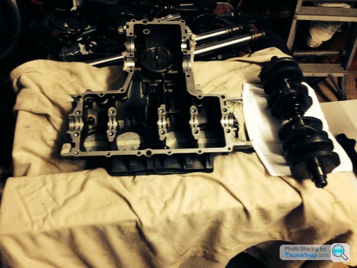
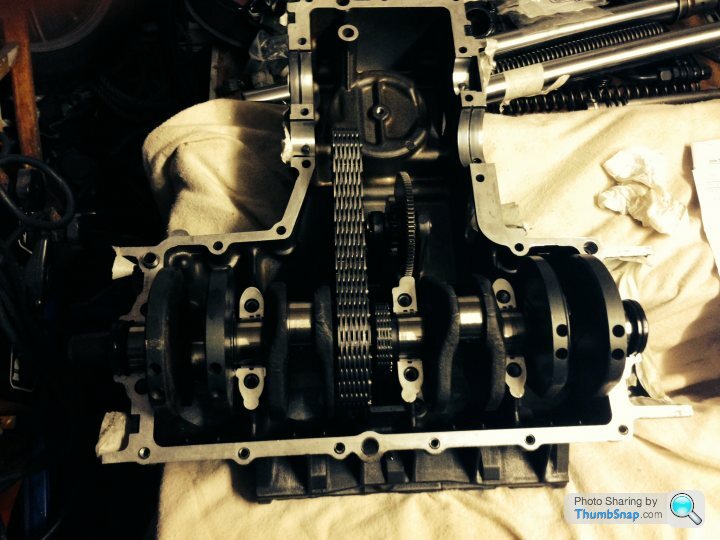
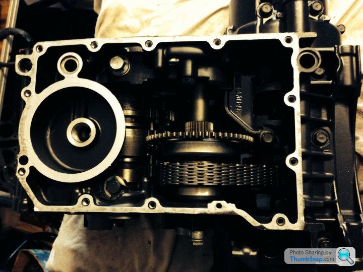
The next step was to put the gearshafts in to place. The gear were checked but had no noticeable wear. The large ball bearings also seemed perfect. The small needle rollers (one at the end of each shaft) felt worn so were replaced. The trusty old torque wrench was dusted dowm and prepared for the mating of the crankcases. 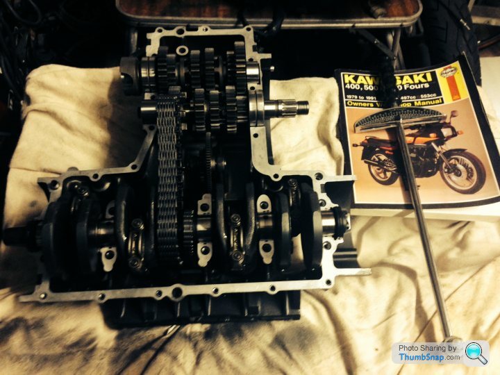
The upper and lower crankcases ready to be mated. All the bolts were cleaned and test-fitted. The masking tape labels were attached when dismantling so that each bolt was numbered, and could be replaced in its original position. Does this matter? I have no idea, but have seen it recommended in many places. 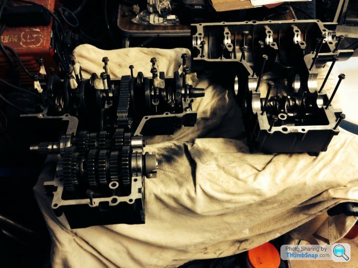
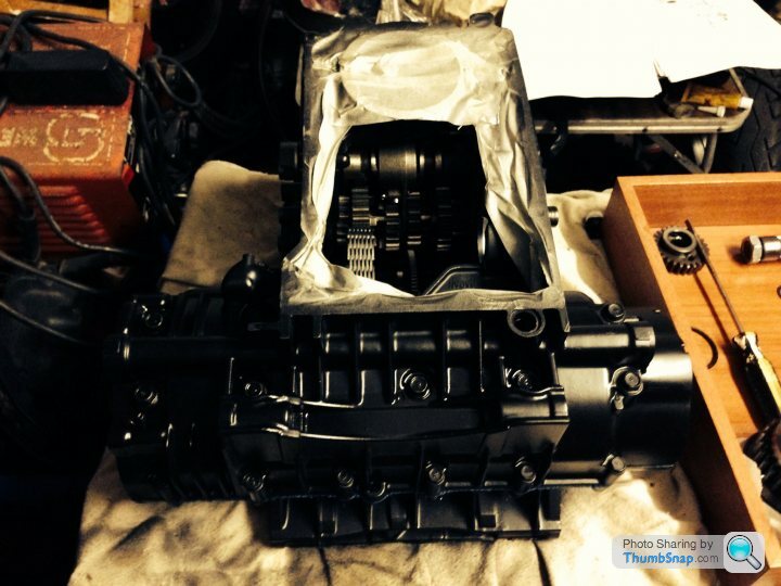
The crankcases are closed and the bolt heads are given a coat of paint. The masking tape keeps the mating surface clear of paint. The main bearing bolts were fitted first, then the lower crankcase bolts, and finally the upper crankcase bolts. The engine was then inverted to fit the primary shaft and oil pump.
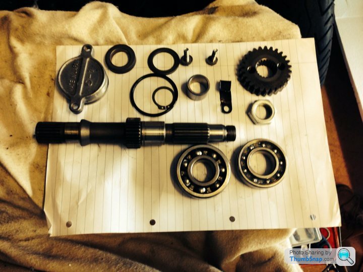
The primary shaft separated into its component parts. One bearing had remained in the crankcase when the shaft was removed. The other had to be pressed off the shaft. Both bearings felt rough when rotated so were renewed. I should at this stage thank Jenna at Premier Power Products in Exeter for her help in sourcing a varied collection of bearings, circlips, and o-rings. Great service and far cheaper than official parts.
The next component for fitment was the oil pump. This was dismantled and a feeler gauge used to check the tolerance between the impeller and the housing.
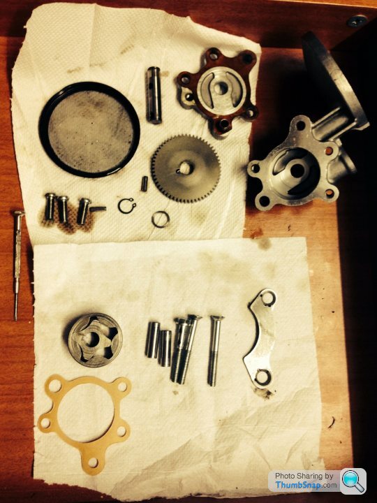
The tolerance was well within the limits so the pump was reassembled with a new gasket and circlip. It was refitted and two screws staked into place.
The tolerance was well within the limits so the pump was reassembled with a new gasket and circlip. It was refitted and two screws staked into place.
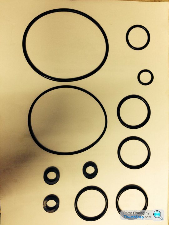
A fresh supply of o-rings in a range of sizes. Four are for the air pressure balance on the front forks. The remainder are needed to refit the oil sump and oil filter. Jenna at Premier Power Products sourced these for a fraction of the cost of Kawasaki original parts.
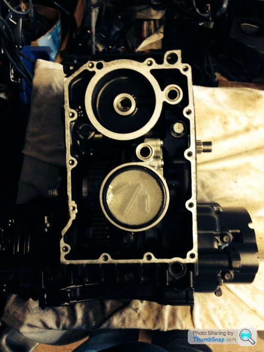
The sump fitted and work on the bottom end of the engine completed. The engine is now ready for fitting to the frame.
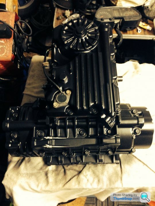
The sump fitted and work on the bottom end of the engine completed. The engine is now ready for fitting to the frame.
Gassing Station | Biker Banter | Top of Page | What's New | My Stuff