Two stage fan cooling
Discussion


Modwise have informed me they no longer supply their two stage fan cooling kit, so I've decided to make my own.
Electrickery is not my strong point so any one who's is the know tell me which of these drawings is correct?
A.
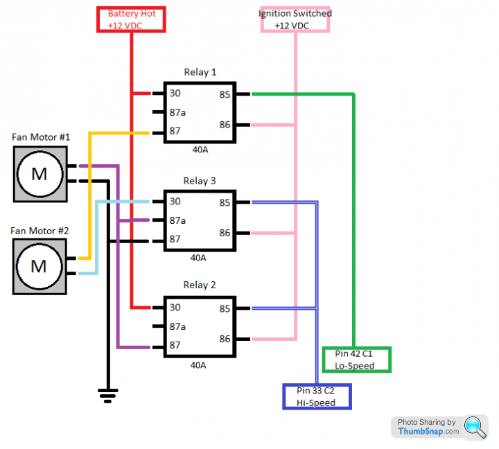
B.
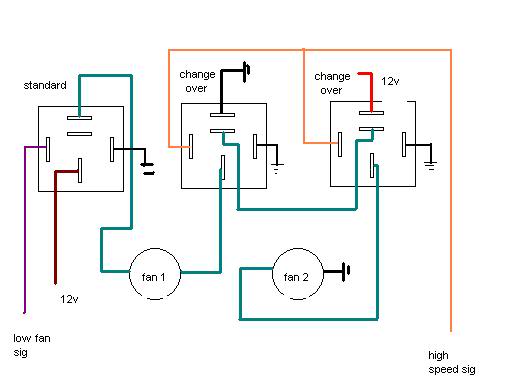
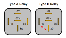
based on type B relay
i will be using the existing swirl pot otter switch plus an inline otter switch to give me the two stage temperatures so a hot side and a cool side. i also have 3 fans a 16" push fan in front of the intercooler. A 12" standard spal fan and 9" universal fan in pull mode with a shroud behind the rad.
Any constructive comments on which fans should do what and when would be helpful.
cheers
I could also wire the push fan so it comes on as when the temps are low or high.. thoughts?
Electrickery is not my strong point so any one who's is the know tell me which of these drawings is correct?
A.
B.
based on type B relay
i will be using the existing swirl pot otter switch plus an inline otter switch to give me the two stage temperatures so a hot side and a cool side. i also have 3 fans a 16" push fan in front of the intercooler. A 12" standard spal fan and 9" universal fan in pull mode with a shroud behind the rad.
Any constructive comments on which fans should do what and when would be helpful.
cheers
I could also wire the push fan so it comes on as when the temps are low or high.. thoughts?
Edited by Discopotatoes on Friday 3rd February 22:39
Steve_D said:
Either circuit will work.
You could drive the 16" from an air temp sensor.
Also saw somewhere a cowl which had flaps in it so that when up to speed if the airflow was higher than the fans could produce the flaps were forced open allowing max flow through the rads.
Steve
Interesting idea, how would you wire the air temp sender? You could drive the 16" from an air temp sensor.
Also saw somewhere a cowl which had flaps in it so that when up to speed if the airflow was higher than the fans could produce the flaps were forced open allowing max flow through the rads.
Steve
Not quite sure I understand what you mean about the cowl,
Edited by Discopotatoes on Saturday 4th February 13:32
Steve_D said:
Discopotatoes said:
Steve_D said:
Either circuit will work.
You could drive the 16" from an air temp sensor.
Also saw somewhere a cowl which had flaps in it so that when up to speed if the airflow was higher than the fans could produce the flaps were forced open allowing max flow through the rads.
Steve
Interesting idea, how would you wire the air temp sender? You could drive the 16" from an air temp sensor.
Also saw somewhere a cowl which had flaps in it so that when up to speed if the airflow was higher than the fans could produce the flaps were forced open allowing max flow through the rads.
Steve
Not quite sure I understand what you mean about the cowl,
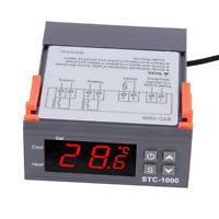
Buy it here for £7. (How the hell can they do it for that price)
http://www.ebay.co.uk/itm/Digital-STC-1000-All-Pur...
Fit the sensor in the induction pipework. Better still get two of them and fit them either side of the cooler and rig some relays to only trip the fan at a certain temp difference across the cooler.
Re the shroud.
If you are using 12" & 9" fan then that is the max area of cooling no matter how large the rad is or how fast you are driving. With those fans there will be areas of the shroud which could be modified by fitting simple hanging flaps over holes cut in the shroud. At slow speeds, say in traffic, the fans will be pulling and the flaps will remain closed. When travelling at speed the air being forced in will be more than the 12/9 combo can deal with so the flaps will be force open giving more air flow.
Steve
Steve_D said:
Discopotatoes said:
Steve_D said:
Either circuit will work.
You could drive the 16" from an air temp sensor.
Also saw somewhere a cowl which had flaps in it so that when up to speed if the airflow was higher than the fans could produce the flaps were forced open allowing max flow through the rads.
Steve
Interesting idea, how would you wire the air temp sender? You could drive the 16" from an air temp sensor.
Also saw somewhere a cowl which had flaps in it so that when up to speed if the airflow was higher than the fans could produce the flaps were forced open allowing max flow through the rads.
Steve
Not quite sure I understand what you mean about the cowl,
Buy it here for £7. (How the hell can they do it for that price)
http://www.ebay.co.uk/itm/Digital-STC-1000-All-Pur...
Fit the sensor in the induction pipework. Better still get two of them and fit them either side of the cooler and rig some relays to only trip the fan at a certain temp difference across the cooler.
Re the shroud.
If you are using 12" & 9" fan then that is the max area of cooling no matter how large the rad is or how fast you are driving. With those fans there will be areas of the shroud which could be modified by fitting simple hanging flaps over holes cut in the shroud. At slow speeds, say in traffic, the fans will be pulling and the flaps will remain closed. When travelling at speed the air being forced in will be more than the 12/9 combo can deal with so the flaps will be force open giving more air flow.
Steve
ETA Found some flaps

Edited by Steve_D on Saturday 4th February 15:56
Penelope Stopit said:
I have spotted 2 problems with this set-up
If a fan motor fails the other fan motor will stop working when in series with it
When running fans in series I would expect them to be identical fans
I haven't time to look at the different problems that may be caused by a sticking or open circuit relay
If I was wiring multiple fans needing 2 or 3 speed settings I would wire them through resistors to control the speeds, relays would be used for the switching, doing the job this way you won't lose the lot in one hit
Thanks for your suggestion, I'm a bit of an electrical numpty so bare with me, how would you wire three fans all different sizes with relays and resistors? It's the relays that get me confusedIf a fan motor fails the other fan motor will stop working when in series with it
When running fans in series I would expect them to be identical fans
I haven't time to look at the different problems that may be caused by a sticking or open circuit relay
If I was wiring multiple fans needing 2 or 3 speed settings I would wire them through resistors to control the speeds, relays would be used for the switching, doing the job this way you won't lose the lot in one hit
Penelope Stopit said:
Discopotatoes said:
Thanks for your suggestion, I'm a bit of an electrical numpty so bare with me, how would you wire three fans all different sizes with relays and resistors? It's the relays that get me confused
There are that many possibilities, it would be best for you to decide and list what the best set-up is, when/what fan/fans are to kick in at what temperatures/thermal switchingThe relay wiring shouldn't be too difficult, the relays could be wired to use resistors for slow speeds or bridge out the resistors for fast speeds
Terminals 30 and 87 of a relay or 30 and 87a could be used to join each end of a resistor hence linking it out
Then all three on full speed if the cold side temps trigger the switch.
Not sure if this is the best way to do it
this is what i have to work with


Edited by Discopotatoes on Saturday 4th February 18:41
Penelope Stopit said:
Are you in any rush to do this?
Are the Otter Switches insulated return 2 X wires ON/Off and the bodies do nothing or are they Body = return switching On/Off down 1 x wire
Id like to have a go at the wiring next week if possible.Are the Otter Switches insulated return 2 X wires ON/Off and the bodies do nothing or are they Body = return switching On/Off down 1 x wire
The otter switches are two wire negative switching both sit in the coolant so the bodies do nothing i believe
Edited by Discopotatoes on Saturday 4th February 20:29
Penelope Stopit said:
Discopotatoes said:
Id like to have a go at the wiring next week if possible.
The otter switches are two wire negative switching both sit in the coolant so the bodies do nothing i believe
OK I have a rough diagram in front of me and it does what you requireThe otter switches are two wire negative switching both sit in the coolant so the bodies do nothing i believe
Edited by Discopotatoes on Saturday 4th February 20:29
I will sit back and see what you think about other posters suggestions
I don't want to waste my time drawing a half decent diagram for you if you aren't going to need it
Will check back here later or tomorrow
keith-vznby said:
To get a similar effect more simply, I left one standard fan on the otter switch with a manual override and ran the second on an adjustable thermostat which gives a number of variables seems easier to me.
i don't like manual overrides as ill forget to turn it on, i already have both otters so would like to use themPupp said:
Late to the party and appreciate I'm not answering the original Q but never quite understood the logic of the two stage fan mod... if it's too hot, I want air in until it isn't. When it's cool enough, the blown air can cease...
Why over complicate stuff?
The Amp draw on 3 fans was massive,2 running at half speed then all kicking in on full when needed should spread the load, also everything working gradually reduced the potential for thermal shock, but i may be talking bWhy over complicate stuff?
 ks on that score
Bluebottle said:
Unless you want to have input from two different heat sources, you could simplify this by using a 3 pin otter switch Useful link here
Thanks for the link that's very useful. but yes two separate inputs one on the original swirl pot and one on the return Pipe to the pump.My thinking is the otter switch changed position over the years so both positions are valid, and if one otter were to fail I should still have fans
Edited by Discopotatoes on Sunday 5th February 15:05
David Beer said:
I would run two in series for the half(ish) speed, then switch all three to max, that way only two temperature points. Quite easy to wire up ,the full speed voltage a 'top up' supply from the starter motor to save any extra through the fuse box.
I think I've made a division, I had the same question on a forum on FB and got very similar replies both for resistors and running in series with good arguments for and against,I think for ease of install I'm going with Davids suggestion which I know is similar to what others have said so apologies if I haven't credited you with the solution.
I shall post my results when I've completed it
Thanks for all your input
Disco
Penelope Stopit said:
Discopotatoes said:
David Beer said:
I would run two in series for the half(ish) speed, then switch all three to max, that way only two temperature points. Quite easy to wire up ,the full speed voltage a 'top up' supply from the starter motor to save any extra through the fuse box.
I think I've made a division, I had the same question on a forum on FB and got very similar replies both for resistors and running in series with good arguments for and against,I think for ease of install I'm going with Davids suggestion which I know is similar to what others have said so apologies if I haven't credited you with the solution.
I shall post my results when I've completed it
Thanks for all your input
Disco
It would be wrong of me to not comment that you have made a bad decision
Wiring motors in series is a poor mans choice and is a very poor method
One motor relies on the other motor for it's supply and vice versa one motor relies on the other motor for it's return, the slightest difference between motors will have a big affect on how one motor compaired to the other motor will run
If one motor fails, the other motor fails
It is impossible to individually fuse 2 motors when wired in series
I have read many articles that have been posted to the internet about many electrical solutions/circuits etc, you may be surprised to know that there are far more incorrect posts than correct posts
Anyone posting here that wiring motors in series is the best method does so due to a lack of experience/knowledge
As I have already mentioned above, wiring motors in series is a poor mans choice, some manufacturers use the poor mans choice as it is a cost cutter

Penelope Stopit said:
Discopotatoes said:
Penelope Stopit said:
Discopotatoes
I have drawn a diagram that will do a proper job. You may be interested

Thank you. P.S. much appriciated I have drawn a diagram that will do a proper job. You may be interested
can you clarify this bit I've highlighted please

Edited by Discopotatoes on Monday 6th February 20:53
I will post a better one shortly
also the bank of two relays have a small box which is the same symbol that each of the fans has. is this a connector or something else?
Edited by Discopotatoes on Monday 6th February 21:26
Penelope Stopit said:
Discopotatoes
I have drawn a diagram that will do a proper job. You may be interested
OK Edited the cock up

These 2 Fuses are main Fuses

These 5 x fuses, 1 at each of the relay coil terminals are 3 AMP safety fuses

These 3 x fuses 1 at each Fan Motor are to protect from short circuits or faulty Motors drawing too much current
For the correct rating of the Main and Fan Motor fuses, the fans need running and the current consumption measuring, now the circuits can be fused accordingly
The circuits aren't to be wired with fuses all over the place, all fuses go in 1 or 2 fuse boxes, the diagram layout is only for simplicity and easy viewing/understanding
Thats brilliant thanks.I have drawn a diagram that will do a proper job. You may be interested
OK Edited the cock up
These 2 Fuses are main Fuses
These 5 x fuses, 1 at each of the relay coil terminals are 3 AMP safety fuses
These 3 x fuses 1 at each Fan Motor are to protect from short circuits or faulty Motors drawing too much current
For the correct rating of the Main and Fan Motor fuses, the fans need running and the current consumption measuring, now the circuits can be fused accordingly
The circuits aren't to be wired with fuses all over the place, all fuses go in 1 or 2 fuse boxes, the diagram layout is only for simplicity and easy viewing/understanding
Edited by Penelope Stopit on Monday 6th February 21:44
i love learning about new stuff and different ways to do it.
would the wiring also depend on the Amp draw in this instance or is there a standard?
Gassing Station | Chimaera | Top of Page | What's New | My Stuff