Speeduino install update.
Discussion


I thought I'd share some of my trials so far in getting a Speeduino ECU installed in my Chimaera.
It's been a bit if of a surprise just how much time it's taken to do all the ancillary work. I think I could have built about 10 Speeduino ECUs in the time it's taken so far and there is a ton of work still to do before I get to try and start it.
Some photos:
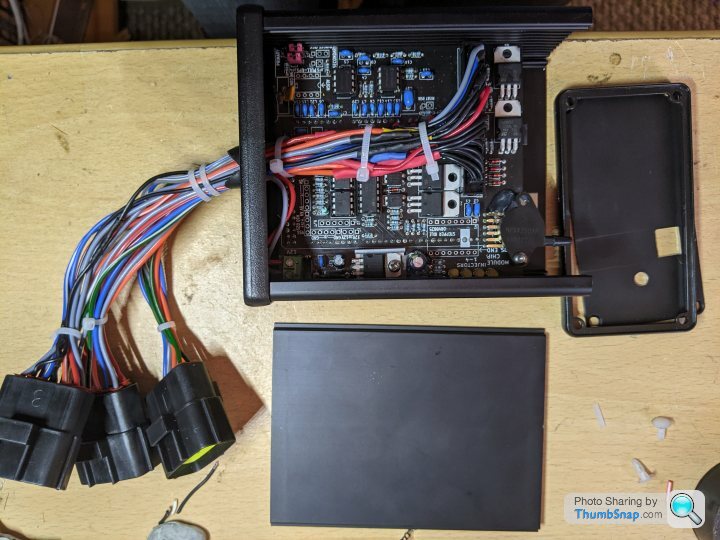
Here's the ECU, probably the easiest part of the project. Having said that I royally screwed up the first board when I soldered the IDC header upside down and then couldn't desolder it. Basically had to start again but it's quick to assemble with basic soldering skills.
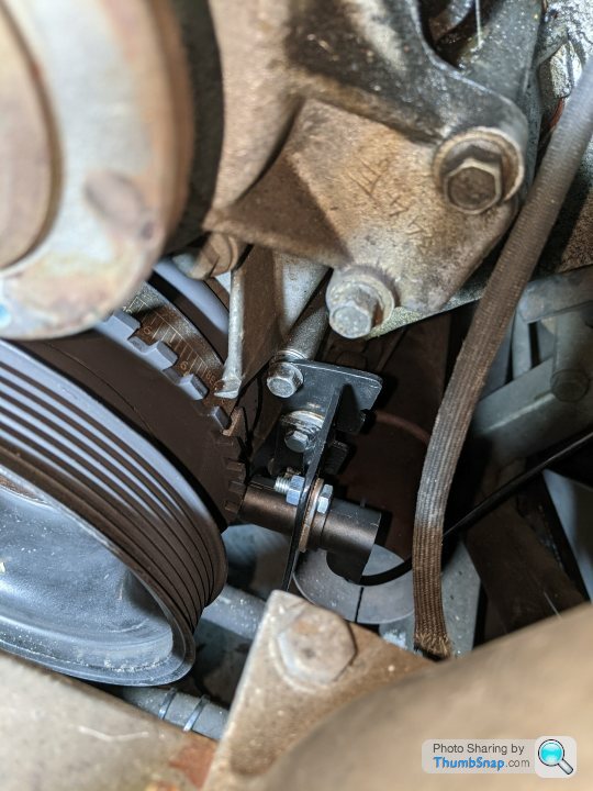
The trigger wheel install took a long time to get right. I made it really hard for myself by starting with a generic 36-1 trigger wheel from ebay.. It was too large to mount behind the damper so had to sandwich it between the front pulley and damper. This at least enabled me to re use the splash shield on the rear. I'm using a BMW E36 Hall sensor and I fabricated a 2 piece bracket which adjusts for clearance on the wheel.
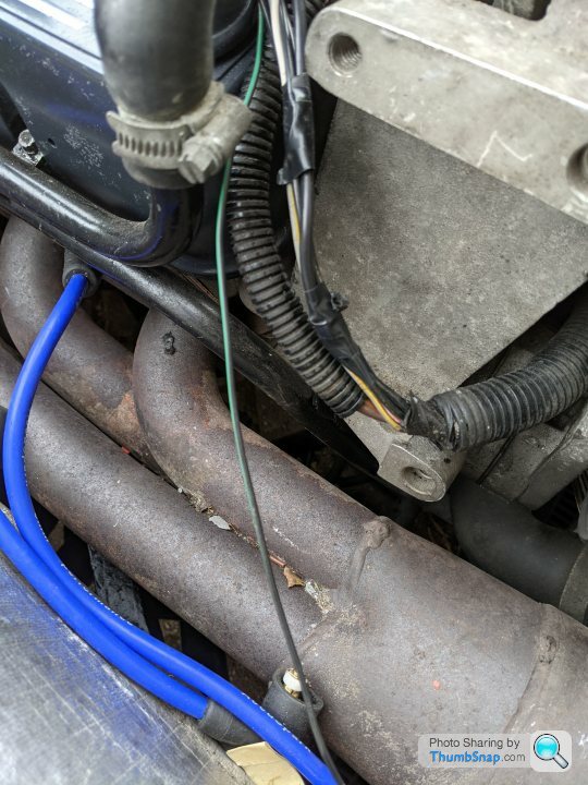
If you look closely you'll spot my original mistake welding in the bung for the wideband. That wasn't a good day when I tried to refit the Y piece. On the flipside I managed to get my Y piece both in and out without dropping the exhaust, or even undoing the support bracket on the system. No tie straps needed either to get the manifold flanges to go into place.

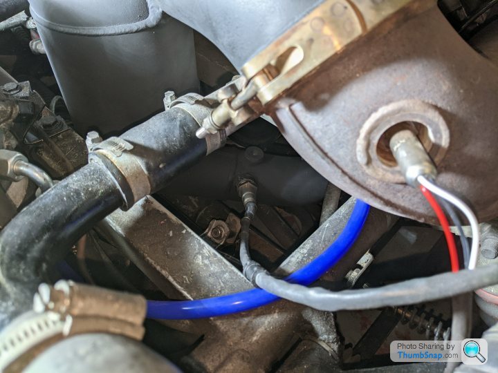
AFM delete pipe fabricated, from a 150mm long 3" diameter steel pipe and welded on a M12 nut. IAT sensor screws in here.
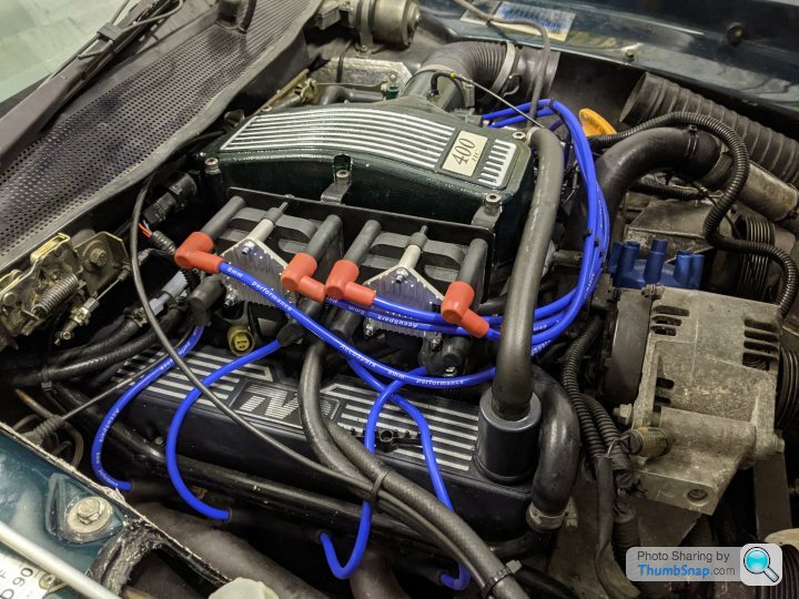
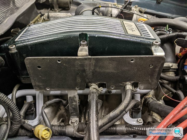
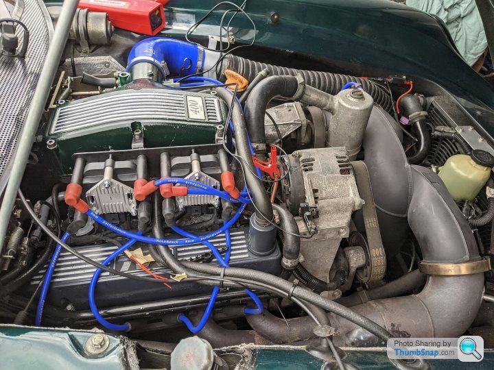
Trial fit for VW coil packs, bracket and custom HT leads. This took forever to get right but it kind of looks like it should be there from stock.
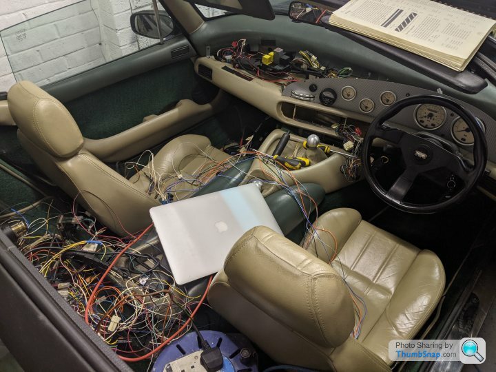
Still working my way through this lot. I've ripped out all the old stuff and now installing new wiring loom. Hoping to bypass the old fusebox and install a new 'sub' fuse/ relay box for the critical ignition and fuel pump relays and fuses. Going to be here a while as it's taking forever to work out the wiring. Thanks Steve_D on here for help with wiring diagrams.
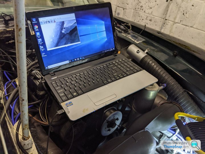
Lastly just for fun...Make sure your inlets are well covered if the plenum is off when working in the engine bay. I dropped a drill tap somewhere and couldn't find it for days. I convinced myself it had gone in one of the intake trumpets. eBay came to the rescue with a endoscope camera for the princely sum of £6. It wasn't in the ports but the scope eventually found it under the rad!
Loads still to do - Also need to sort a fix for the Tachometer. I want to run it from the ECU - It has an output but will need some sort of conversion box to get the voltage up to the usual levels it would see from the negative on the old coil. Suggestions welcomed there. Can't decide either whether to run without a cold start valve or get a simple PWM 3 port one. I've already bypassed the stepper valve I think it will be a nightmare to implement on the new ECU. Fan control is another issue. Again can control run from the new ECU but will need some thinking about.
More soon.
It's been a bit if of a surprise just how much time it's taken to do all the ancillary work. I think I could have built about 10 Speeduino ECUs in the time it's taken so far and there is a ton of work still to do before I get to try and start it.
Some photos:
Here's the ECU, probably the easiest part of the project. Having said that I royally screwed up the first board when I soldered the IDC header upside down and then couldn't desolder it. Basically had to start again but it's quick to assemble with basic soldering skills.
The trigger wheel install took a long time to get right. I made it really hard for myself by starting with a generic 36-1 trigger wheel from ebay.. It was too large to mount behind the damper so had to sandwich it between the front pulley and damper. This at least enabled me to re use the splash shield on the rear. I'm using a BMW E36 Hall sensor and I fabricated a 2 piece bracket which adjusts for clearance on the wheel.
If you look closely you'll spot my original mistake welding in the bung for the wideband. That wasn't a good day when I tried to refit the Y piece. On the flipside I managed to get my Y piece both in and out without dropping the exhaust, or even undoing the support bracket on the system. No tie straps needed either to get the manifold flanges to go into place.
AFM delete pipe fabricated, from a 150mm long 3" diameter steel pipe and welded on a M12 nut. IAT sensor screws in here.
Trial fit for VW coil packs, bracket and custom HT leads. This took forever to get right but it kind of looks like it should be there from stock.
Still working my way through this lot. I've ripped out all the old stuff and now installing new wiring loom. Hoping to bypass the old fusebox and install a new 'sub' fuse/ relay box for the critical ignition and fuel pump relays and fuses. Going to be here a while as it's taking forever to work out the wiring. Thanks Steve_D on here for help with wiring diagrams.
Lastly just for fun...Make sure your inlets are well covered if the plenum is off when working in the engine bay. I dropped a drill tap somewhere and couldn't find it for days. I convinced myself it had gone in one of the intake trumpets. eBay came to the rescue with a endoscope camera for the princely sum of £6. It wasn't in the ports but the scope eventually found it under the rad!
Loads still to do - Also need to sort a fix for the Tachometer. I want to run it from the ECU - It has an output but will need some sort of conversion box to get the voltage up to the usual levels it would see from the negative on the old coil. Suggestions welcomed there. Can't decide either whether to run without a cold start valve or get a simple PWM 3 port one. I've already bypassed the stepper valve I think it will be a nightmare to implement on the new ECU. Fan control is another issue. Again can control run from the new ECU but will need some thinking about.
More soon.
Polly Grigora said:
This is an amazing project
Great job
Wiring loom should be good fun
Is the battery up-front or down the back?
Thanks! Battery will be up front for now - Just going to tidy up the rats nest and get the main and fuel pump relays into a nice mini fusebox. I'm also really tempted to bypass the main fusebox which is probably corroded and way past its best and take a good ignition live into the mini fusebox to do the critical ignition, ECU and fuel circuits. Will be easier to access too. I ditched my immobiliser already so that at least isn't a concern.Great job
Wiring loom should be good fun
Is the battery up-front or down the back?

geordiepingu said:
Relatively few things you will cut through, oil pressure, oil sender, coolant temp and alternator excite light. Otter switch return is on the same bunch of connectors, you can use a low - medium current output to trigger it as stated above to bypass the otter switch. For your tacho, you can get a conversion box from Extra EFI. I think a few other places like trigger-wheels.com will sell the same unit
That sounds hopeful thanks.  . I think I've sorted the tacho last night. Found a circuit online which converts the low voltage pulsed output from Speeduino into a bigger pulse for the tacho, using a 2N5551 transistor and a relay coil to create the spike. I had the bits already and built it, just to find a nice little enclosure for it.
ric355 said:
I also made an AFM delete pipe, and I also put the IAT sensor in there. However, I don't run it there anymore because it suffers from terrible heat soak and I presume this comes from the exhaust manifold just below it. That makes the IAT correction curve very hard to tune. In fact it should not need tuning at all really beyond the one in the base tune (which is based on the ideal gas law), but you'll find hot starts are awful with it there and it'll start leaning out in traffic with resultant rpm oscillation.
Mine is now "installed" in the nose cone away from the heat soak. I say installed, what I mean is it is tie-wrapped to the inlet hose just as it comes out of the inner wing on the air filter side. So it's out of the wind but the other side of the bulkhead away from hot engine air. This works a lot better.
Hey ric355. Thanks for all your comments above, really useful stuff particularly on the heat soak issue. This might actually inadvertently solve another issue I have in that my new silicon 90 degree hose isn't actually long enough to reach the delete pipe. If I relocate it further down and bring the old inlet pipe to meet the hose it could solve both problems.Mine is now "installed" in the nose cone away from the heat soak. I say installed, what I mean is it is tie-wrapped to the inlet hose just as it comes out of the inner wing on the air filter side. So it's out of the wind but the other side of the bulkhead away from hot engine air. This works a lot better.
OK, I'm fairly close now to being able to power up the ECU for the first time.
I took the good advice here and relocated the MAF delete pipe down the front of the car with the IAT sensor to avoid heatsoak from the exhaust.
The new wiring loom is in, sensors are all connected, wideband is all wired up, and cooling fans now set up to control from the new ECU, but I need to sort some remaining earths. I have 3 black wires, one thick gauge and 2 smaller gauge that are running from under the engine and past the alternator along with the alternator cable, oil pressure sender and switch wires.
These appear to be earths of some kind and originally terminated in the old ECU and I think the green A/C socket which isn't used. Since I chopped out the old ECU I now have 3 loose earths in the passenger footwell. Can someone confirm what the 3 earths are for and do I still need them?
Thanks. Yes they are checking out as earths on the multimeter. I think to be sure I best jack the car up and see where they terminate. Will be a good chance to check that the condition of starter cable is ok too.
Good advice on the ecu grounds. My plan is to earth it on the back of the cylinder head with the new earth for the main relay. The Speeduino ECU doesn't have a dedicated 0v pin for the negative output of the AEMs AFR gauge so it's that currently tied to a ground in the ECU so I do need to check for ground loops.
Good advice on the ecu grounds. My plan is to earth it on the back of the cylinder head with the new earth for the main relay. The Speeduino ECU doesn't have a dedicated 0v pin for the negative output of the AEMs AFR gauge so it's that currently tied to a ground in the ECU so I do need to check for ground loops.
ric355 said:
Use the ECU for sensor grounds (there are several pins available for this) but not for power grounds.
Thanks, yes this is what I thought might be best. Got them all now distributed on the GND pins. Then I guess the Speeduino board will tie these to a power GND which I'll probably earth on the bolt behind the LH cylinder head.drcarlos said:
I like the install of the coilpacks there. I had to move mine late last year to re-instate the drivers footwell heater hose as they were installed behind the plenum and blocked it's install (this resulted in frozen feet and the inability to drive in cold weather). I ended up picking up on a couple of much smaller bolts on the inlet manifold and making a couple of spacers so they are flat on top of the rocker. They don't feel that stable so either need a 3rd mount or a larger pair like the bolts on the plenum you've used, another job on the list.
The install as a whole I feel is great and a major contributor into the fact I can just get in, drive my car most of the time and it just seems to work (there seems to be so issues with distributers, coils and amplifiers on other car and getting rid of that lot for this kit just removes a multitude of failure points). It will probably breakdown on the way home tonight now
Thanks, it's reassuring to hear your car is better to drive now. That's my aim really with this whole install. I just want it to work so I can enjoy driving it. I had nothing but persistent problems with the whole OE setup.The install as a whole I feel is great and a major contributor into the fact I can just get in, drive my car most of the time and it just seems to work (there seems to be so issues with distributers, coils and amplifiers on other car and getting rid of that lot for this kit just removes a multitude of failure points). It will probably breakdown on the way home tonight now
Yes I found that too that you really need a third support as the VW coil packs are surprisingly heavy. I've got 2 supports at the top to the existing plenum bolts and another bolt to the inlet manifold.
This photo shows it more clearly. I also later welded some long bolts directly to the plate so the coilpacks can be changed with ease if necessary.
OK hit a bit of a snag.
All the wiring is done but I just did a quick sanity check with the multimeter across the terminals before connecting the battery and I have a short when the ignition is switched on.
So ignition off > open circuit - all good.
Switch ignition on > positive shorted to ground.
I've traced the short to something on the ignition circuit going to Fuse 21. If I remove Fuse 21 (battery feed to ignition) the short disappears so it must be something on this circuit. If I remove any of the other fuses, the short is still there.
I've taken all the relays out and removed all the ECU, injector, coil pack circuits and still it's there.
Any ideas?
Belle427 said:
You say it’s a short but does it actually blow fuse 21?
This is a good question.. The chances are it won't because although the multimeter is showing it as a short the true resistance/load is around 2 ohms. This would supply a current of 6Amps through the fuse, so unlikely to blow the 20A fuse but what on earth could be taking 6A just by switching the ignition on? None of the circuits relating to the Speeduino are now connected as I took all the fuses but still have that same indicated load so to me that still indicates a short As far as I can tell Fuse 21 just supplies the ignition switch and 2 fuses 8 and 12 from that. But if I remove both those fuses then the load is the same.
I really don't want to connect it to a battery like this as there's a very good chance something will melt.
Thanks for the replies. Just to say all relays and fuses to the Speeduino circuits are disconnected and the short is still there.
But as Polly has said it may not be a short at all. If there is a genuine short it would literally have to be downstream of Fuse 21 and upstream of my new fuse box which supplies the Speeduino and all associated circuits, (coil packs/ injectors etc.)
I'm going to try connecting the battery with a 20amp safety fuse on the negative cable and see if it blows... Will report back.
Quick update on the Speeduino install.
I sorted the short, but to be honest I've no idea what caused it. I think I must have chased myself around in circles as it miraculously disappeared and hasn't reappeared.
Anyway the good news is It's Alive! I had a real battle getting the Speeduino timing synced with TDC but after some crude measuring of the angle and trial and error found the right angle as -72 deg. Also had a bit of a mare getting the fuel pump to prime which was a dodgy fuse connector.
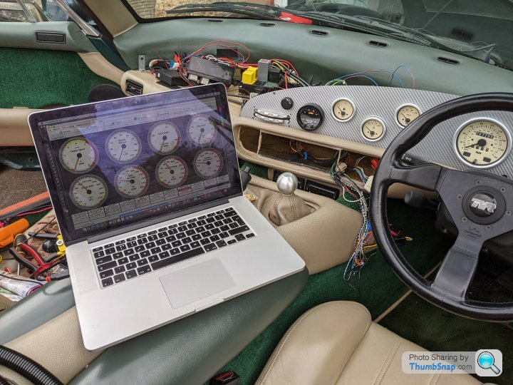
It now starts and runs but, idle speed is way too low. The fans are working fine, controlled by the ECU (bye nasty Otter Switch) and the coolant gauge is spot on with the readout in Tuner Studio. Map Sensor is working fine. Currently idles at 27kPA.
A few gremlins still to sort. My Tachometer adapter circuit isn't working but doing an awful lot of clicking for some reason.
So it's on to getting it running smoothly. First some petrol as I'm about to run out!
Really pleased so far. Thanks for all the help so far!
I sorted the short, but to be honest I've no idea what caused it. I think I must have chased myself around in circles as it miraculously disappeared and hasn't reappeared.
Anyway the good news is It's Alive! I had a real battle getting the Speeduino timing synced with TDC but after some crude measuring of the angle and trial and error found the right angle as -72 deg. Also had a bit of a mare getting the fuel pump to prime which was a dodgy fuse connector.
It now starts and runs but, idle speed is way too low. The fans are working fine, controlled by the ECU (bye nasty Otter Switch) and the coolant gauge is spot on with the readout in Tuner Studio. Map Sensor is working fine. Currently idles at 27kPA.
A few gremlins still to sort. My Tachometer adapter circuit isn't working but doing an awful lot of clicking for some reason.
So it's on to getting it running smoothly. First some petrol as I'm about to run out!
Really pleased so far. Thanks for all the help so far!
Yeah I was using a dial back and then I realised it was just confusing the issue further so just set it on zero.
It's just the same setup as MS2. Lock the timing at 10deg before TDC in Tuner Studio and then adjust the trigger angle until you get a sync on the 10 deg mark on the pulley. As I found though you need a rough idea first of what the angle is or you'll never pick up the mark on the strobe. Finally found it and it synced up nicely.
It's just the same setup as MS2. Lock the timing at 10deg before TDC in Tuner Studio and then adjust the trigger angle until you get a sync on the 10 deg mark on the pulley. As I found though you need a rough idea first of what the angle is or you'll never pick up the mark on the strobe. Finally found it and it synced up nicely.
Polly Grigora said:
Surely it is the relay coil that's altering the pulse and the relay armature should be removed to stop the relay from chattering
Or
Am I missing something?
It's all about inductance produced by the relay coil isn't it?
That was what I thought too. I might have wired it wrong across the contacts or something...Will pull it out and check again.Or
Am I missing something?
It's all about inductance produced by the relay coil isn't it?
Gassing Station | Chimaera | Top of Page | What's New | My Stuff