Winter rebuild
Discussion


Morning folks, currently the racer is stripped down to a bare chassis. Is anyone interested if I was to write up a "progress report" up periodically similar to Leigh's Tasmin rebuild? http://www.pistonheads.com/gassing/topic.asp?h=0&a...
If it's something folks will be interested in I'll put the effort in to do it.
Regards
Iain
If it's something folks will be interested in I'll put the effort in to do it.
Regards
Iain
Ok ok, I get the message  The current state of play is the chassis is stripped, and up on axle stands. There is an old SD1 Vistesse engine sat in it as a buck and thats it. The body is outside awaiting modification, I'm picking up a hard top today then the plan is to build up the suspension, starting at the front because thats all new, decide what I'm doing with my cooling system and a few opther bits, then once its been built as a dry build, strip everything back down, get the chassis, cage and suspension powder coated, body sprayed and a new loom before building back up and testing in the spring.
Regfards
Iain
The current state of play is the chassis is stripped, and up on axle stands. There is an old SD1 Vistesse engine sat in it as a buck and thats it. The body is outside awaiting modification, I'm picking up a hard top today then the plan is to build up the suspension, starting at the front because thats all new, decide what I'm doing with my cooling system and a few opther bits, then once its been built as a dry build, strip everything back down, get the chassis, cage and suspension powder coated, body sprayed and a new loom before building back up and testing in the spring.Regfards
Iain
Right folks, by way of introduction for those who don't know me and my car...
I bought the Chimaera in June 2005 with the intention of keeping the car as close as possible to standard road spec as possible. This went out of the window when my dad wrapped the backend of it around a lamp post the day after my 24th birthday in August 2005. The car was the first race car I had built from scratch, however I've been tinkering with cars most of my life and have a degree in Automotive Engineering.
2006 was a torrid season, my inexperience really showed and I had more mechanical DNFs that any other result, and the rest of the time the car and I invariably tried to throw eachother backwards into the scenery. 2009 I wholly intend to be a different story.
Right enough of that. The car. As I've already said the car is now stripped down to a bare chassis with just a buck of an engine in place. I have the main intentions with this rebuild of righting the mistakes of the 2005/6 build, where there are obvious performance upgrades to be had without wasting time or money reinventing the wheel to do them and finally to make the look worthy of a racetrack, not the shabby motor it was.
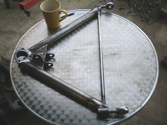
The first upgrade that's being made is to swap to rose jointed front suspension. Several reasons for this, firstly I had to replace the upper rear poly-bushes a couple of times through the season due to heat damage from the exhaust manifolds, also in 2009 I'm running slicks and the rose-jointed wishbones will allow me to run much more camber. This is what I've been tinkering with this weekend. I took delivery of the wishbones last weekend, on Friday I went to DT and picked up 8 rosejoints...sadly I got 7 of one size and 1 of the other instead of 4 of each, something I didn't pick up on that until this morning. Anyway I've been able to build up one wheel station (almost). Once I get my replacement rose joints I'll be looking at setting up the front geometry.
Right some photos...
New lower wishbone
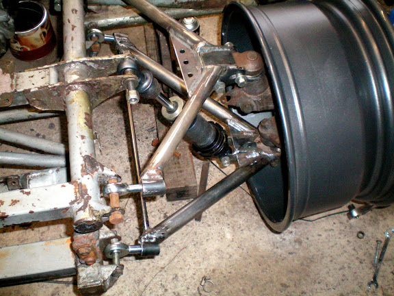
NSF wheel station
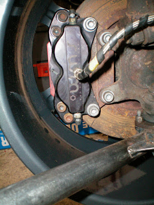
Inside view of the (new) wheels...mmmm now have room for bigger brakes
Note how shabby everything looks, once everything is built and correct, I'll be stripping everything down, acid dipping the chassis and anything that is to be powder coated. However when doing the first build, things are as they are, when say three bolts are used in the example of the lower ball joints, I'll only use two for example.
Any questions just shout!
Regards
Iain
I bought the Chimaera in June 2005 with the intention of keeping the car as close as possible to standard road spec as possible. This went out of the window when my dad wrapped the backend of it around a lamp post the day after my 24th birthday in August 2005. The car was the first race car I had built from scratch, however I've been tinkering with cars most of my life and have a degree in Automotive Engineering.
2006 was a torrid season, my inexperience really showed and I had more mechanical DNFs that any other result, and the rest of the time the car and I invariably tried to throw eachother backwards into the scenery. 2009 I wholly intend to be a different story.
Right enough of that. The car. As I've already said the car is now stripped down to a bare chassis with just a buck of an engine in place. I have the main intentions with this rebuild of righting the mistakes of the 2005/6 build, where there are obvious performance upgrades to be had without wasting time or money reinventing the wheel to do them and finally to make the look worthy of a racetrack, not the shabby motor it was.
The first upgrade that's being made is to swap to rose jointed front suspension. Several reasons for this, firstly I had to replace the upper rear poly-bushes a couple of times through the season due to heat damage from the exhaust manifolds, also in 2009 I'm running slicks and the rose-jointed wishbones will allow me to run much more camber. This is what I've been tinkering with this weekend. I took delivery of the wishbones last weekend, on Friday I went to DT and picked up 8 rosejoints...sadly I got 7 of one size and 1 of the other instead of 4 of each, something I didn't pick up on that until this morning. Anyway I've been able to build up one wheel station (almost). Once I get my replacement rose joints I'll be looking at setting up the front geometry.
Right some photos...
New lower wishbone
NSF wheel station
Inside view of the (new) wheels...mmmm now have room for bigger brakes
Note how shabby everything looks, once everything is built and correct, I'll be stripping everything down, acid dipping the chassis and anything that is to be powder coated. However when doing the first build, things are as they are, when say three bolts are used in the example of the lower ball joints, I'll only use two for example.
Any questions just shout!
Regards
Iain
Edited by Chassis 33 on Monday 20th October 08:27
Hello again folks, right the past few weeks I've been doing quite a bit of stuff that can't really be put into words and pictures, wondering about chassis stiffness and scrub radii and the like, any way recently I've been going all Blue Peter! My mind visualises things and I need to sometime mock things up either on CAD or in real life so some thoughts about stiffening the chassis have been made into cardboard reality, well not really just a few bits of gaffer, a saw and some cardboard tubes from the inside of plotter rolls.  It's all a bit best guess TBH, I haven't the time to model everything up and do an FEA analysis on things, sadly. Maybe if I get my hands on a spare chassis next year I will do.
Anyway some photos of random bits of cardtube, to try and stiffen the engine bay area.


I've also been asking folks for a few bits of help http://www.pistonheads.com/xforums/topic.asp?h=0&a... so thanks to those who've replied. I'll be ordering my wheels in time for Christmas.
Hopefully this coming weekend I can sit around and measure various different bits of geometry to see what happens when I do X Y or Z, with the suspension very roughtly set up I'm getting about 2mm of bump steer from straight ahead position through the travel of the shock, so I'm hoping to reduce that.
Regards
Iain
It's all a bit best guess TBH, I haven't the time to model everything up and do an FEA analysis on things, sadly. Maybe if I get my hands on a spare chassis next year I will do.Anyway some photos of random bits of cardtube, to try and stiffen the engine bay area.
I've also been asking folks for a few bits of help http://www.pistonheads.com/xforums/topic.asp?h=0&a... so thanks to those who've replied. I'll be ordering my wheels in time for Christmas.
Hopefully this coming weekend I can sit around and measure various different bits of geometry to see what happens when I do X Y or Z, with the suspension very roughtly set up I'm getting about 2mm of bump steer from straight ahead position through the travel of the shock, so I'm hoping to reduce that.
Regards
Iain
Still no pictures to show you, however the tinkering with the suspension has been very useful, the chassis is now being prepped for welding in new tubes to stiffen the car, the idea is to increase the torsional stiffness of the chassis and reduce the amount of deflection of the top wishbone mounts. I've also been in conversation with Gaz (well Derek at AbShocks) regarding damper option for the 2009 season, so watch this space.
The other interesting bit that has happened, well intersting to me, is that the shell has gone to a secret location somewhere near Kidderminster for a nose job, and some other bodywork fettling. The idea is that front end will lift away, as per the Tuscan racers and some of the Tasmin racers and improve access to the engine bay of the car, not to mention the weight reduction. When I next head down to Kiderminster I'll take some photos and let you know whats happening.
Regards
Iain
The other interesting bit that has happened, well intersting to me, is that the shell has gone to a secret location somewhere near Kidderminster for a nose job, and some other bodywork fettling
. The idea is that front end will lift away, as per the Tuscan racers and some of the Tasmin racers and improve access to the engine bay of the car, not to mention the weight reduction. When I next head down to Kiderminster I'll take some photos and let you know whats happening.Regards
Iain
Sprayed aluminium eh? Tell me more 
Right I think its about time you mighty fine chaps and chappesses had an update.
Unfortunately due to the cold weather and one thing and another I'm still waiting on my body to return from having all its modifications, and as such its somewhat hampering progress, as I need the body to complete the chassis alterations. Until the chassis is altered I can't send it for dipping and can't get on with building it up. However...
I have spend a hell of a lot of time prepping various bits and pieces
So far all the suspension components and many of the engine components have been cleaned up, spruced up and had replacement bearings, ball joints, bushes etc. throughout.


I've sent a rear upright assembly off to Keri at WMS to have some brackets made up to run 4-pot calipers at the rear. The initial plan was to compliment these with a set of 6pots at the front and about a 330mm disc; however because of the current £/$ exchange rate the cost of ordering in a pair of 6pots from his supplier has gone through the roof so initially I'll "only" be running a very large 4pot at the front with a view to running the 6-pot when either the exchange rate is more favourably or I win the lottery.
Once the body is back the chassis work that needs doing includes
Once that's sorted, I plan to build up the rolling chassis and get the suspension geometry fettled, before the body goes on as it improves access.
Then its something like
If you want any more specific details just holler
Regards
Iain
Right I think its about time you mighty fine chaps and chappesses had an update.
Unfortunately due to the cold weather and one thing and another I'm still waiting on my body to return from having all its modifications, and as such its somewhat hampering progress, as I need the body to complete the chassis alterations. Until the chassis is altered I can't send it for dipping and can't get on with building it up. However...
I have spend a hell of a lot of time prepping various bits and pieces
So far all the suspension components and many of the engine components have been cleaned up, spruced up and had replacement bearings, ball joints, bushes etc. throughout.
I've sent a rear upright assembly off to Keri at WMS to have some brackets made up to run 4-pot calipers at the rear. The initial plan was to compliment these with a set of 6pots at the front and about a 330mm disc; however because of the current £/$ exchange rate the cost of ordering in a pair of 6pots from his supplier has gone through the roof so initially I'll "only" be running a very large 4pot at the front with a view to running the 6-pot when either the exchange rate is more favourably or I win the lottery.
Once the body is back the chassis work that needs doing includes
- fabricating radiator mounts
- straps for the seats mounts and the pedal box mount (granted these can be done without the body as I marked the positions before the body went)
- mounts for front body work and splitter
- lower mount for the steering column
- chassis pickups for rear spoiler (if i choose to run one)
- brackets to attach flat floor (unless I mount it to the body of the floorpan)
Once that's sorted, I plan to build up the rolling chassis and get the suspension geometry fettled, before the body goes on as it improves access.
Then its something like
- body on
- exhaust system fabricated
- plumb all the fluids
- new wiring loom
- map the Megasquirt ECU
- the other 20million little bits and pieces that should only take 5mins but end up taking an eternity
- shake down at a local airfield
- test at Oulton
- hopefully be out for Donington in May because to be out for Cadwell is going to be a very close call.
If you want any more specific details just holler
Regards
Iain
im said:
^^^
Thats excellent update Iain - keep them coming.
BTW you do realise your parents mis-spelled the name Ian right?
Carry on.
Nah, they just copied it off a friend whos parents had mis-spelt his name. Thats excellent update Iain - keep them coming.
BTW you do realise your parents mis-spelled the name Ian right?
Carry on.
Tyre_Tread said:
Ian, I only just found this thread. Well done my man.
I wish I was closer as I'd love to see it in the flesh and maybe lend a hand.
I'll tell Steph that you're campaigning again this year (spoke to her earlier today).
Cheers I wish I was closer as I'd love to see it in the flesh and maybe lend a hand.
I'll tell Steph that you're campaigning again this year (spoke to her earlier today).
 How's she doing these days?
Regards
Iain
Hello again boys and girls, I'm still waiting on the body, still waiting on my next contract too, I've been out of work since November! Anyway I've been cracking on with the wiring for the engine electrics which has got me thinking, I'm dangerous when I think. Anyway the long and the short of things is that the wiring loom I'm using as the basis of the engine electrics comes from a Disco II that I bought a bulk lot of bits from a number of years ago, loom sensors, manifolds etc etc. The engine I'm going to be building up originated in a P38 Range Rover and had a 36-1 trigger wheel fitted to the flex plate as standard. This got me thinking, instead of usinga trigger wheel mounted to the front pulley where it is exposed, ungainly (IMO) and fouls where I want to mount the alternator, was there some way of combining the P38 tigger wheel with a manual flywheel (manual P38's are rare as rocking horse teeth btw), so I can use the OEM crank position sensor seutp.
Anyway I popped over to the engine and drivetrain forum and bounced the idea around there, and after a lot of oooo you'll never get that to work etc a Griff owner came up with "I've thought of that, did all the work, but then I used a different engine so never used it", a quick journey to Stoke and a few beer tokens later I have this

A 2WD flywheel with a groove machined in it to accept the P38 trigger wheel, all I need to decide now is to weld, bolt or Loctite the ring to the flywheel...any suggestions? I'm thinking Loctite 380 may well be the best way to go.

The coil packs I'm using are also from a Disco II, and I'm mounting them onto the Disco manifold, this means that I wont be able to use the traditional trumpet base and plenum as the tracts are in different places. As you can see in the photo, I already have a Tufnol insulating plate for the manifold, what I intend to do with this is to create a trumpet base/lower plenum around the Tufnol spacer and bolt onto the top of this one of Tim Lamont's ACT Carbon Fibre Westfield plenums, with the throttle body (again 68mm Disco II) mounted at the front of the engine with a ram air effect from an intake in the new front end.
Thats it for now.
Regards
Iain
Anyway I popped over to the engine and drivetrain forum and bounced the idea around there, and after a lot of oooo you'll never get that to work etc a Griff owner came up with "I've thought of that, did all the work, but then I used a different engine so never used it", a quick journey to Stoke and a few beer tokens later I have this
A 2WD flywheel with a groove machined in it to accept the P38 trigger wheel, all I need to decide now is to weld, bolt or Loctite the ring to the flywheel...any suggestions? I'm thinking Loctite 380 may well be the best way to go.
The coil packs I'm using are also from a Disco II, and I'm mounting them onto the Disco manifold, this means that I wont be able to use the traditional trumpet base and plenum as the tracts are in different places. As you can see in the photo, I already have a Tufnol insulating plate for the manifold, what I intend to do with this is to create a trumpet base/lower plenum around the Tufnol spacer and bolt onto the top of this one of Tim Lamont's ACT Carbon Fibre Westfield plenums, with the throttle body (again 68mm Disco II) mounted at the front of the engine with a ram air effect from an intake in the new front end.
Thats it for now.
Regards
Iain
The Tufnol can be worked as per any material, think of it as very hard MDF, so I could blend in an entry there, or I may have to mount trumpets to the base to regain the length lost in the hotwire trumpet base. Until I get on a rolling road I wont know but reducing down a set of trumpets and doing back to back runs every 5 or 10 mm isnt going to be difficult, albeit a little time consuming. The other option I have, that I've toyed with in the past is to run the rear section of the Thor rams head inlet and bolting a pair of throttle bodies to the front...kinda like...

2x68mm throttles give circa 500hp everything else being appropriate obviously, so more than plenty for my 300hp target, although having such large throttles may give bad manners around town, it shouldn't be an issue on a racer
The only vacuum connection I need is for the MAP sensor, and even then its arguable as to whether I need that on a racer, I'm not running a brake servo with the new pedal box, and obviously not running a dizzy so no need for vacuum advance. Although I do have a Thor ECU I'm going to be running Megasquirt, between Joo and Phil Ringwood I've got an ECU that offers everything I want for peanuts. I dont know about the trigger wheel for a Thor set up, however the P38 setup pictured is 36-1
Right I'm off to attempt to get drunk on Budwieser and stuff myself with nachos in time for Daytona.
Regards
Iain
On MS, you can map directly against engine speed and TPS with corrections for temperature like you have done with the Emerald, or map MAP vs TPS and engine speed. Both work ok on a racer, so long as you dont have massive altitude variations eg pikes peak, arguably MAP vs gives a more refined setup for better low speed manners.
Regards
Iain
Regards
Iain
Hello again, since my last post I've been exploring the Thor inlet some more, an I've found some interesting (well to me anyway) bits out about the inlet. Firstly all the inlet tracts from manifold face back to the opening are as far as I can make out the same length, the second and possibly more useful bit on information that I hadn't clocked in the past is that the tracts are arranged in such a fashion that neither mini-plenum has two consecutive cylinders drawing air from it at any one time. Well that's not strictly true because you'll get an amount of overlap but most importantly you don't get 5 & 7 fighting against each other for air. The reason for this is that the front and rear pair of tracts on each bank loop back and feed the cylinder they sit above, however the middle pair of tracts cross over and feed the opposite cylinder...does that make sense...?
Anyway for the time being I'm going to pursue this option to see where it leads me, my next hurdle is creating adaptors from the round throttle bodies to the rectangular Thor inlet as you can see in one of the earlier pictures. To do this I'm going to make a pair of adaptors out of glass fibre. I went to my local garden centre and bought one of those Oasis blocks for flower arranging, they cost £1 each for something about 12in long and er brick shaped...
From this I found a glass tumbler that was the same Id as the Id of the exit of the throttle body..approx 69mm, and pressed it into the end of 1/3rd of the Oasis block. I marked the other up as an appropriate size to the rectangle then took a large kitchen knife and sculptured two of these, they take about 10mins each

and wrapped them in parcelling tape (I checked and the glassfibre the resin doesn't stick to the parcelling tape)

then cut four 100mm squares from MDF to make a former for the mating faces, also a few short lenghts of coat hanger wire to hold everything together...

so putting things together I have this...

My next challenge is to figure out how to make the two mating faces stay parallel to eachother while I lay up the glass fibre, then it will be a case of hand fettleing the bores to remove the kinks etc.
Regards
Iain
Anyway for the time being I'm going to pursue this option to see where it leads me, my next hurdle is creating adaptors from the round throttle bodies to the rectangular Thor inlet as you can see in one of the earlier pictures. To do this I'm going to make a pair of adaptors out of glass fibre. I went to my local garden centre and bought one of those Oasis blocks for flower arranging, they cost £1 each for something about 12in long and er brick shaped...
From this I found a glass tumbler that was the same Id as the Id of the exit of the throttle body..approx 69mm, and pressed it into the end of 1/3rd of the Oasis block. I marked the other up as an appropriate size to the rectangle then took a large kitchen knife and sculptured two of these, they take about 10mins each
and wrapped them in parcelling tape (I checked and the glassfibre the resin doesn't stick to the parcelling tape)
then cut four 100mm squares from MDF to make a former for the mating faces, also a few short lenghts of coat hanger wire to hold everything together...
so putting things together I have this...
My next challenge is to figure out how to make the two mating faces stay parallel to eachother while I lay up the glass fibre, then it will be a case of hand fettleing the bores to remove the kinks etc.
Regards
Iain
Leigh the adaptors are approx 4" long and I'd argue that 5mm of glassfibre (the depth of the returns for the flanges) will be stronger than 3mm of ali, and less likely to fatigue. As you can see from the photo of the two gaskets below, a decent length is going to be needed to get a blend between the two x-sections which is why I've gone for an adaptor peice instead of a blended plate.

Peter, all good points. The X-section is going from approx 36cm^2 down to approx 30cm^2 so a shade under 20%, over a 4in loft its a fairly smooth affair.
WRT to the rose joints, its something I've queried in the past...the Malaysian Chim racers had their rosejoints with a vertical mounting bolt, however Tuscan racers have it horizontal, as per a standard bush arrangement, the vertical arrangement is the stonger design and something im looking into.
Regards
Iain
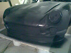
Hi, right I've been away from computerdom for the past fortnight. Have I missed anything? What I do have are some photos of when I went to Kidderminster to have a bit of a tyre kick regarding the body. The previous photo was effectively the buck that the front end mould was taken from. The mould now looks something like this
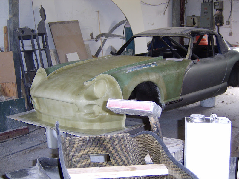
When it's all back together the lights will be faired in as per the run-out edition and have the Lupo light conversion, just to freshen up the existing design without going down the "Speed Six" route.
The roof is going to take its basis from the Tuscan Challenge cars, you can spot one the glassfibre guys had knocking about from a previous project, however it will be modified to create something of a fast back to help reduce the aerodrag commonally associated with the notch-back design, I'll then be using an underbody venturi and an end mounted single plane blunt nose aerofoil (read functional spoiler not a chavtastic Halfords affair) to balance the aero created by the front splitter and dam
Regards
Iain
Holy thread ressurection Batman!!!
The Chim has been put on hold recently mainly due to the length of time its taken to get the main body back, but also cos I've changed jobs moved house etc etc all those horrible things you do when you become a grown up which stop you from doing what you want to do which is playing with cars. Anyway, I'm promised the body back this weekend and by way of a teaser...

Regards
Iai
The Chim has been put on hold recently mainly due to the length of time its taken to get the main body back, but also cos I've changed jobs moved house etc etc all those horrible things you do when you become a grown up which stop you from doing what you want to do which is playing with cars. Anyway, I'm promised the body back this weekend and by way of a teaser...
Regards
Iai
Afternoon folks, this thread is likely to have more come backs than Rocky Balboa!
Just to say since the last post I've moved house (again) found myself a decent workshop, some spare cash and intend to crack on with the Chimaera as soon as possible. I'll try and keep you posted
Regards
Iain
Just to say since the last post I've moved house (again) found myself a decent workshop, some spare cash and intend to crack on with the Chimaera as soon as possible. I'll try and keep you posted
Regards
Iain
Edited by Chassis 33 on Wednesday 8th September 13:22
Right folks, its time to break cover, I've alluded to it for a while, no, I'm not gay, well not very, I am however re-engining the Chimaera.
The RV8 has had a very distinguished career getting to the dizzy heights of F1, but these days its a bit long in the tooth, 300hp+ is expensive to achieve and even more expensive to achieve reliably. My solution to this is to drop in an Audi ABZ engine normally found in late 1990's vintage A8s.
The spec will be something roughly like
4172cc V8, power/torque target 325hp (flywheel) / 320lbft
Megasquirt ECU running launch control, flat shift and TC
Target cost £1000, budget £1200
So far I've spent £400 on the engine, £100 on the ECU and about £10 in fasteners and MDF to make the pattern for the bell housing adaptor, the other great expense will be custom exhaust manifolds. I've a thread covering the transplant running on another forum (sorry Haymarket) and as I'm inherently lazy I'm not going to duplicate things so the link is http://www.motorgeek.com/viewtopic.php?f=6&t=3...
Regards
Iain
Gassing Station | Chimaera | Top of Page | What's New | My Stuff