95 Griff random wires
Discussion


So another thread I’m starting which I hope will get me through tracing random ripped out wires. I have a few, some easier to trace than others so first one is below:
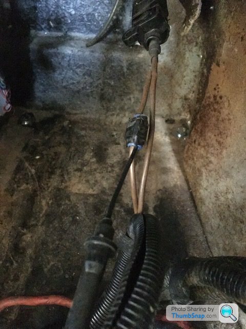
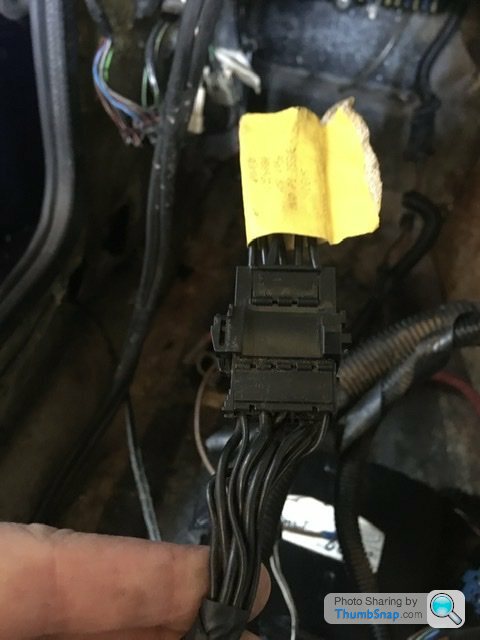
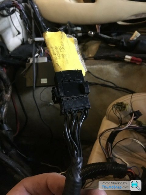
First wire is shown is in the picture below. It’s passenger side (rhd) attached to a micro switch on the central locking solenoid. It has a blade fuse attached mid way but it’s been pulled off somewhere hence a bare end on the cable.


If I had dismantled the car myself I would have taken pictures accordingly for reassembly. I didn’t rip these wires.
My fingers are crossed and thanks in advance for any help
First wire is shown is in the picture below. It’s passenger side (rhd) attached to a micro switch on the central locking solenoid. It has a blade fuse attached mid way but it’s been pulled off somewhere hence a bare end on the cable.
If I had dismantled the car myself I would have taken pictures accordingly for reassembly. I didn’t rip these wires.
My fingers are crossed and thanks in advance for any help
Belle427 said:
I seem to remember a mod for a mag switch at the rear somewhere to open the boot using a microswitch here.
Worth checking.
That makes sense. My car had that mod so it’s for that then Worth checking.
I’ll have another look in the morning and hopefully confirm that

Cheers guys
I’ll post next random wire soon

Belle427 said:
See if it energises in the crank position, if so it's the world famous hot start mod.
It's a terrible botch whatever it is.
Multiple blacks are normally immobiliser related so be careful!
Usually the hot start mod is spliced into those blacks in the connector.
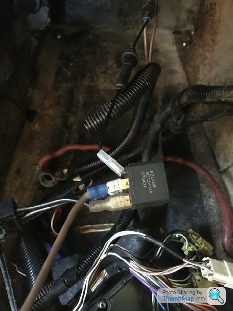
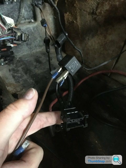
Right so I seem to have had an unspliced connection fitted onto the bunch of black wires. Which makes that scotch lock relay redundant.It's a terrible botch whatever it is.
Multiple blacks are normally immobiliser related so be careful!
Usually the hot start mod is spliced into those blacks in the connector.
Edited by Belle427 on Monday 20th March 08:35
The info from Bertram-Hill is interesting. The mods to wiring for the windows and windscreen I’ll definitely do. I might as well move the fuse board to the glove box as well while I have good access to the wiring.
A few years back I did modify the battery box to slide a battery in and out without removing the battery box via the bolts through the floor. I think now is the ideal time to finish that mod thoroughly.
A few years back I did modify the battery box to slide a battery in and out without removing the battery box via the bolts through the floor. I think now is the ideal time to finish that mod thoroughly.
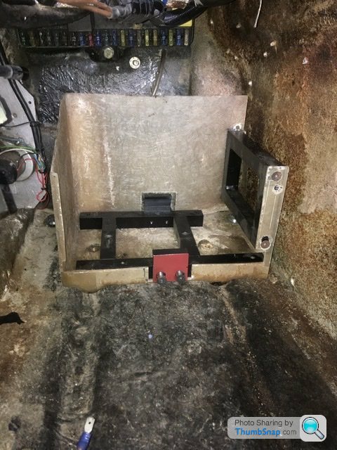
Here is the cut up and altered battery box.
If you notice the grooves in the body floor, the opposite is present on the base of the battery box but to fit within those grooves the box needed a bit of trimming off the right hand side and the right hand rear corner to clear the body mounting bolt. I made a frame to fit within so it clamps the box from underneath then made a pair of clamps to hold the base of the battery. So that allows removal of the battery by removing the red painted clamp. The battery then slides out. It still needs finishing but the basics are there.
BIG DUNC said:
That looks good. I toyed with the idea of doing something similar, but in the end I refitted the original battery box.
Cheers. Just thought might as well finish this while everything is stripped out. The fuse box behind I’m going to move to the glove box which then gives space to mount the ecu behind the battery box. The rats nest of wires on the battery isn’t the greatest by tvr lol.That’s really good. The map switch with mot made me smile
I’ve spent all my budget so I’m making good with what I have unfortunately. Anything damaged I’ll repair/replace accordingly. My engine has been tuned but it’s old skool now which I’m happy with. Maybe the next owner will do the ecu change who knows
With regards to stereo I’m fitting a pair of slim mount 8” subs in enclosures behind the seats and under the centre console area. The amp will be mounted on the panel with the rear vents but in the boot. That’s my plan. I’ll put the pictures and more detail in the restoration thread when I’m doing that.
It’s the mass of wires I’m working through here.
Ideally I’d like nothing on the battery when finished. So it’s an easy slide in or out affair.
I’m also looking at doing some wiring mods to the electric window feeds and wipers so they actually move effectively rather than laboured.
Yeah lots to chip away at still
Well stereo plan is as follows
Alpine cdm-7892 up front. Was looking for a pioneer prs 80 but a good deal was had on the alpine unit.
Front speakers are new old stock kicker 5 1/4” components. I’m using slightly smaller units as I hate chasing door rattles so as I’m cutting frequencies there is no point in big front speakers.
Tweeters will be mounted where the door ashtray currently resides. I’m fitting all new trim so I’ll repair the ashtray holes and fit the tweeters nicely first.
Those will be run via an active crossover. The pioneer unit does this using it’s built in pre-outs. Haven’t got that now so a stand alone unit will be used. I have a nice kenwood unit to do that. Not sure where to mount that as yet. Because it’s Kenwood I want it hidden from view so the system looks just Alpine and kicker.
Then I have 2 new old stock kicker resolution 8” shallow mount subs. Rather than waste space making a complete enclosure, I will bond directly to the fibreglass body. Exact enclosure sizes still to be measured but that’s how I’m doing it. Again I’ll trim and carpet accordingly as it will all be new.
Amplifier is a new old stock kicker impulse 6 channel to be mounted in the boot behind the rear speaker/vent panel.
A very simple system but run active. The alpine headunit also has a time alignment facility so I can use that and fine tune everything using h/u and amplifier crossovers.
Then for a bit of old skool nostalgia a cd changer, alpine to replace the original pioneer unit.
All new cables will be used and all hidden. especially on the amplifier. The dash gauges will have the illumination changed to green to match the alpine h/u.
The rear speaker/vent holes I’ll cover with a pair of perforated leather covers to match the new trim.
In theory I should have a nice punchy bass/sub bass sounding system rather than a low rattling sub bass system.
With the roof down you will only see the door speakers. Nothing outrageous. I’m after a sort of 90’s-2000’s factory upgrade look.
That’s the plan
Johno said:
Looking forward to seeing it done! I don’t have ash trays, if I had I would have considered a recessed tweeter mount in the space and modded the cards accordingly ahead of its retrim. But no existing holes and wishing to keep it as subtle as I can I opted for coax’s with a recessed tweeter as a compromise.
I do think running a DSP is a good solution as it allows the control of all elements from crossovers to phasing, time alignment etc. The Pioneer unit I have is good, with all elements covered, but it’s also limited. Perfectly adequate for my system via pre-outs. I nearly extended the budget for an amp with integrated DSP, but space and cost - plus a dose of healthy realism of what could be achieved meant I stepped back. I also really wanted it hidden in the footwell.
Similar to you I wanted a subtle system, without horrible looking speaker installs with crap looking grilles etc. I went 165 fronts to make the most of the 2 ways and get the lower frequency response, running with a 50hz HPF, 80 for the rears. They do reach lower, but not sub levels! The rears you’d hardly notice versus existing vents.
Door cards treated with sound deadening and all loose wires etc checked to eradicate any rattles. Will treat rear bulkhead when it’s back home.
Are you going to use the rear earthing point location behind the fuel tank for the amp? Saves a lot of additional cabling?
I enjoy the challenge when fitting car audio. So getting a good sound in an open top car is difficult. The kicker speakers I have have lovely plain black cones, grilles and a subtle badge. The mesh grille is of the full speaker type not a later funky kicker style. I do have a second set of matching 4” components and toyed with 8” door mounted woofers with the 4” components but it would be too much and not very tasteful. I do think running a DSP is a good solution as it allows the control of all elements from crossovers to phasing, time alignment etc. The Pioneer unit I have is good, with all elements covered, but it’s also limited. Perfectly adequate for my system via pre-outs. I nearly extended the budget for an amp with integrated DSP, but space and cost - plus a dose of healthy realism of what could be achieved meant I stepped back. I also really wanted it hidden in the footwell.
Similar to you I wanted a subtle system, without horrible looking speaker installs with crap looking grilles etc. I went 165 fronts to make the most of the 2 ways and get the lower frequency response, running with a 50hz HPF, 80 for the rears. They do reach lower, but not sub levels! The rears you’d hardly notice versus existing vents.
Door cards treated with sound deadening and all loose wires etc checked to eradicate any rattles. Will treat rear bulkhead when it’s back home.
Are you going to use the rear earthing point location behind the fuel tank for the amp? Saves a lot of additional cabling?
The earth point in the boot I didn’t know about. I’ll be removing the fuel tank to trim the boot again which then allows fitment of the amplifier and associated cables. The fuel tank I’m thinking I might use the interior colour vinyl and I might stitch that to match the seat insert tuck and roll pattern. If the tank is out it wouldn’t take long to cover it.
So lots of ideas at the moment
Back to wires. So I’m looking at the original heated seat circuit. To turn on the heated seats you use one of the heater controls, pull on, push off. My car wasn’t fitted with heated seats from the factory. Now I’m assuming both seats would be heated but from only one on/off button. Is that correct? Or would the factory only fit a heated element in the drivers seat?
Just wondering how robust the original switch is to now use being nearly 30 years old?
Or just fit my own new circuit and switch for each seat?
Just wondering how robust the original switch is to now use being nearly 30 years old?
Or just fit my own new circuit and switch for each seat?
sixor8 said:
My first Chimaera in 2001 (a 1995 model) had heated seats. It was a button on the cowl close to the steering wheel, the same type as the dashboard illumination on / off. It wasn't labelled of course. 
My present Griff doesn't have them but the owners manual does state they would come on pressing one of the buttons.
I think (but not completely sure) that it heated both seats because I remember stuff on the passenger seat getting warm (no weight sensor either), also it was only the squab, the backs didn't heat up.
I was reading up earlier and just found info on that chimaera button. My present Griff doesn't have them but the owners manual does state they would come on pressing one of the buttons.
I think (but not completely sure) that it heated both seats because I remember stuff on the passenger seat getting warm (no weight sensor either), also it was only the squab, the backs didn't heat up.
Interesting the Griff only had warm up cushions. How very bizarre.
I think with that I’ll put my own wiring circuit in.
Question for the wiring and circuit experts.
I’m looking for a main switched ignition live feed from the back of the fuse box. I don’t want to piggy back from an already fused circuit but connect to a main switched live before it supplies the fuse box if that makes sense?
I have 3 circuits to add but I want them all zero volts with the ignition off. The hot start circuit, a heated seat circuit and a relay operated window circuit.
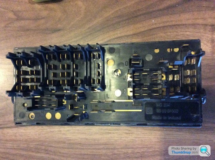
I would like the main power feeds to the relays of each of these circuits to be zero volts until the ignition is turned on. Obviously each fused accordingly. Below is the back of my fuse box L is the main input from the battery. There is a relay on the other side that switches the ignition live circuits but where on the back is an output I can use before it feeds all the switched circuits? If one exists that is?
I’m looking for a main switched ignition live feed from the back of the fuse box. I don’t want to piggy back from an already fused circuit but connect to a main switched live before it supplies the fuse box if that makes sense?
I have 3 circuits to add but I want them all zero volts with the ignition off. The hot start circuit, a heated seat circuit and a relay operated window circuit.
I would like the main power feeds to the relays of each of these circuits to be zero volts until the ignition is turned on. Obviously each fused accordingly. Below is the back of my fuse box L is the main input from the battery. There is a relay on the other side that switches the ignition live circuits but where on the back is an output I can use before it feeds all the switched circuits? If one exists that is?
Polly Grigora said:
1 x White cable - unfused ignition supply - Plug B - Black
2 x White cables - unfused ignition supply - Plug G - Red
1 x White cable - unfused ignition supply - Plug I - Red
Thank you 2 x White cables - unfused ignition supply - Plug G - Red
1 x White cable - unfused ignition supply - Plug I - Red
I was testing earlier and found connection R also a switched main live. As it’s a single spade connection directly above O I think it’s ideally the shortest link to create the switched live circuits under the fuse box via the unused midi fuse.
I appreciate you posting so quickly. It’s good to double check info especially wiring
Polly Grigora said:
RobXjcoupe said:
Question for the wiring and circuit experts.
I’m looking for a main switched ignition live feed from the back of the fuse box. I don’t want to piggy back from an already fused circuit but connect to a main switched live before it supplies the fuse box if that makes sense?
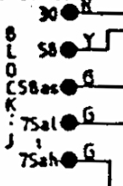
Am as certain as can be (don't know what fusebox you're wiring) that terminal R is common to F/Box Block J terminal 75ah (green cable) which is a fused ignition supply (may well be fuse 16)I’m looking for a main switched ignition live feed from the back of the fuse box. I don’t want to piggy back from an already fused circuit but connect to a main switched live before it supplies the fuse box if that makes sense?
RobXjcoupe said:
I appreciate you posting so quickly. It’s good to double check info especially wiring
You're welcome. Can double check, triple check and still get it wrong. Many wires!Got myself doubting now. My fuseboard is as above in the picture from a 95 Griff 500.
All fuses removed only 1 terminal showed a circuit from the back of the ignition feeds relay, terminal 87 or terminal 26 on the fuse box board. That is block M terminal 75s.
Gassing Station | Griffith | Top of Page | What's New | My Stuff