Transistor Radio Problem
Discussion


I have a battery-powered RGD transistor radio in the garage. It's of great sentimental value, because I've had it since I was five and I'm now fifty-harrumph.
I went out there yesterday and the batteries were flat. Unusual, but not sinister. So I replaced them and all was well. But when I turned the radio off, I noticed if I wiggled the on-off knob, up against the detente, so it was still off, the speaker crackled.
Went to the garage this morning, and the batteries were flat, so the thing is evidently on all the time.
Do I have a hope of fixing this myself, and if so, how?
dontlookdown said:
As it is old, it should come apart easily with ordinary screws etc so you do have a decent chance of fixing it.
The business end of the on/off/volume will be a potentiometer, either surface mounted to a pcb or possibly separate and attached to the case or chassis.
How are you with a soldering iron? If you can unsolder it and ID the part, its quite possible you will be able to find a replacement that is close enough to do the job. Lots are still used and thus they are available.
You don't have to be an electronics genius, just careful and methodical.
Makes sense, thank you. Yes, I can use a spldering iron, and yes, the radio comes apart easily. Now I know what to look for, I'll have a look.The business end of the on/off/volume will be a potentiometer, either surface mounted to a pcb or possibly separate and attached to the case or chassis.
How are you with a soldering iron? If you can unsolder it and ID the part, its quite possible you will be able to find a replacement that is close enough to do the job. Lots are still used and thus they are available.
You don't have to be an electronics genius, just careful and methodical.
Dogwatch said:
A bit late now but I assume the battery is a PP9, so possibly you could have temporarily wired an external on/off switch into the positive lead from the battery using a couple of chocolate block connectors.
6 AAs.I could wire in an external switch but, as I said, I'm pointlessly attached the the radio, and I'd like to fix it, rather than bodge it.

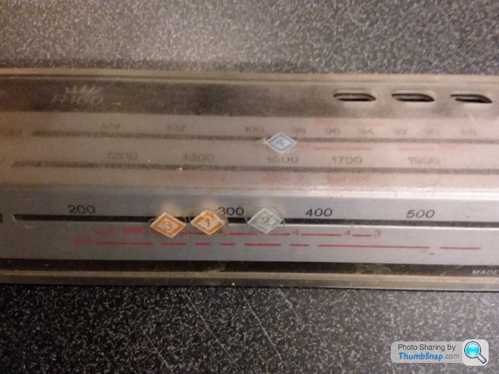
Back in the 1970s, when BBC radio went onto FM (or for some other reason), they gave out some stickers to help you find your favourite stations. It's still got those on it.
Ydnaroo said:
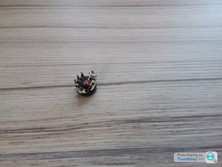
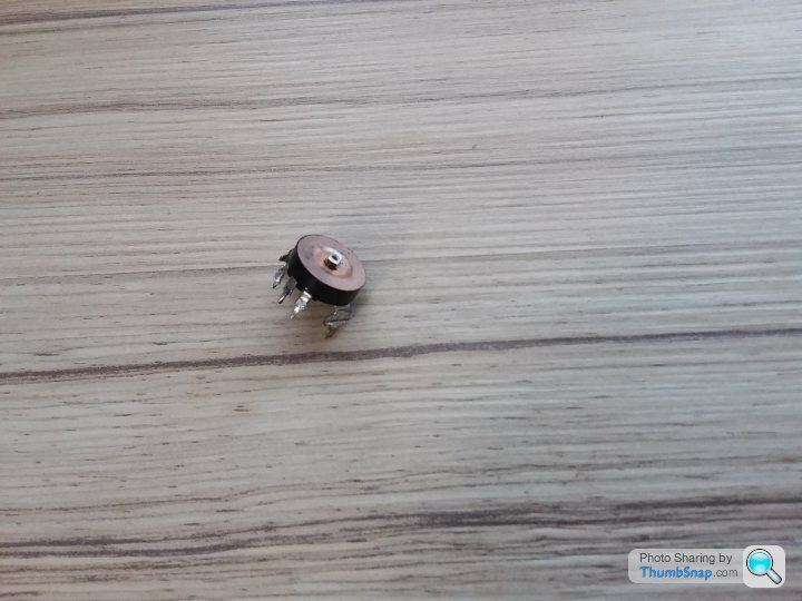
The off/on switch mechanism is the cam on the back of the control, looks like parts have come off.
How about: https://www.ebay.co.uk/itm/ON-OFF-VOLUME-CONTROL-C...
Or: https://www.ebay.co.uk/itm/Switched-Radio-Volume-C...
5k instead of 10k unlikely to make any difference.
The bit that's come off is the knob, which I removed.How about: https://www.ebay.co.uk/itm/ON-OFF-VOLUME-CONTROL-C...
Or: https://www.ebay.co.uk/itm/Switched-Radio-Volume-C...
5k instead of 10k unlikely to make any difference.
That first link looks perfect, thank you!
I spent ages searching eBay for a 'potentiometer' under advice from this thread. Who knew I actually needed an 'an/off switch'?

 ked.
ked.
LunarOne said:
In what way? If it was working before the switch went kaput, then it ought to work again. Unless you fixed it with a sledghammer...?
It does nowt. The switch appears to work in the same way, and I've tested all the continuities. I had to reattach a speaker wire, but when I switch it on, there's no sound, not even a crackle.I've done all the circuit testing I can, so the next step is to reinstall the old switch, and see if I can recreate the fault, in which case I know the new component is at fault.
Mave said:
That original switch looked like a combined potentiometer and switch. The 3 smaller terminals are the potentiometer (also known as variable resistor), the two larger terminals are the power switch. Did you replace the original switch with another with 5 terminals, or did your just attach something to the 2 power terminals? The symptoms you described originally all point to that combined pot / switch, so if it worked before my guess would be that you've wired up the new switch wrongly.
The replacement was identical (but maybe 2mm smaller in diameter). I assumed the five pins do the same thing in each case.Mave said:
Yeah, should do. If you've tested continuity then I guess you've got a multimeter?
I doubt that the new pot/switch is at fault, but if you want to check it - (sorry if I'm teaching you to sick eggs!)
The 2 big terminals either side of the cam are for power - should have infinite resistance when the switch is off, very low resistance as soon as the switch is clicked on with no further change as you rotate it to max volume.
The 3 smaller terminals are for the potentiometer. I'm guessing you have the centre and maybe one other connected. You should have 10k resistance across the outer 2.
If you put your meter across the centre and 1 of the outers it should vary from zero to 10k as you rotate the knob. If you put your meter across the centre and other outer it should also vary from zero to 10k but in the opposite direction.
Have you got a photo of the original installation, and the current installation?
Useful info, thank you. No photo of the origonal installation, no.I doubt that the new pot/switch is at fault, but if you want to check it - (sorry if I'm teaching you to sick eggs!)
The 2 big terminals either side of the cam are for power - should have infinite resistance when the switch is off, very low resistance as soon as the switch is clicked on with no further change as you rotate it to max volume.
The 3 smaller terminals are for the potentiometer. I'm guessing you have the centre and maybe one other connected. You should have 10k resistance across the outer 2.
If you put your meter across the centre and 1 of the outers it should vary from zero to 10k as you rotate the knob. If you put your meter across the centre and other outer it should also vary from zero to 10k but in the opposite direction.
Have you got a photo of the original installation, and the current installation?
LordLoveLength said:
NMNeil said:
Start by identifying the radio and getting the circuit diagram
http://www.kbmuseum.org.uk/reg_rgd.htm
Useful site.http://www.kbmuseum.org.uk/reg_rgd.htm
Looks like an R160 from the earlier photo.
OP double check your speaker wires and battery wires to make sure they are properly connected.
ETA - I see a DC power jack on the rear? Also check wires to/from this and it’s condition. Any issues here will result in a dead set.
Edited by LordLoveLength on Thursday 4th March 15:45
Thanks all.
ETA: That site says the R160 takes 4x AA, but it actually takes 6.
NMNeil said:
Open this up and click on the R160 for the factory circuit diagram in PDF.
http://www.kbmuseum.org.uk/service_manuals.htm
Thank you http://www.kbmuseum.org.uk/service_manuals.htm
Now what do I do?
Gassing Station | Computers, Gadgets & Stuff | Top of Page | What's New | My Stuff