Pingu's Next Project - A Flowbench
Discussion


The answer to your question seems to be very obvious. You have assumed the holes flow at 100% efficiency (discharge coefficient of 1.00) which is vanishingly unlikely and Helgesen has assumed, or more probably measured, about 99%. It's much easier to make simple square edged holes in flat plate (orifice plates) for which the actual flow coefficient can then be calculated using the Stolz equation.
When I built my floating depression bench 30 years ago I made up a set of 4 calibration orifice plates to test it with. These were machined from 1.6mm mild steel plate by clamping each plate between a couple of bits of scrap stock and boring right through which ensured perfect edges (no burrs) on the middle plate. Just boring directly through thin plate is unlikely to achieve very good edges. I then calculated the flow coefficients, which are actually not a constant but vary with the orifice size and the size of the tube it is installed in, and hence the target flows. The larger the orifice diameter inside a given tube (bigger d/D ratio) the higher the flow coefficient. You can read all about this in the British Standard 1042 which I strongly suggest you look at in your local uni library if you want to learn all there is to know about this topic.
Anyhoo, the holes were bored to the nominal sizes I specified of 18, 28, 35 and 40 mm then measured accurately using a bore micrometer rather than just aiming for a target size and hoping for the best. The actual flow coefficients and target flows were then calculated using the Stolz equation with the Reynolds number also factored in.
The results from my 20 quid flowbench at 25" of water were as follows.
Plate #........Diameter mm...flow coefficient....target flow....measured flow
Plate 1...........18.39................0.59817.............34.0...............34.5
Plate 2...........27.94................0.60031.............78.6...............79.3
Plate 3...........35.15................0.60240............124.9.............124.6
Plate 4...........40.41................0.60416............165.6.............164.9
Total................................................................403.1..............403.3
In other words accuracy to within the 1% tolerance of error which BS 1042 says is the best you can work to with turbulent gas flows which are somewhat variable and uncertain at the best of times. The weighted average error of the total flow for the series of plates which might represent the area under the curve of a flow test of a valve throughout its lift range is essentially zero. 0.2 cfm in 400. At low flow rates it reads a smidge high and at higher flows a smidge low but every reading is within a cfm. You are unlikely to get accuracy like this from even an expensive professional bench.
Over the years I tested my bench (or more properly my test plates) against a number of other pro benches. The Superflow 110 benches at Competition Engine Services, the motoring journalist and later Emerald proprietor Dave Walker, and Real Steel in Uxbridge and also a computerised FlowQuik bench a few years ago. For reasons I never had time to investigate, maybe I screwed up the test, the bench at Real Steel flowed about 15% high but all the others were fairly spot on. None as accurate as my own bench though.
I went to all this trouble so I could be certain my bench was accurate and I could compare my results against other people's like Dave Vizard rather than the bench just being a comparator which means you can't set targets for your work for what each head might ultimately be able to flow.
With a Superflow bench you need to calibrate it before each test using the test plate supplied and then each measured flow figure is adjusted by the relevant percentage. My bench is accurate out of the box as designed to the British Standards.
A comparator bench is ok if all you want to know is whether you made things better or worse and by how much but you can never know if there is more flow to come unless you can compare to other people's results and seminal works like Annand and Roe's flow coefficients for real ports.
Thanks very much for that. One of my guesses for the difference was experimentation.
At the moment, I am building a comparative flowbench, but will be aiming to modify (redesign ) it to be able to "measure" CFM.
I prefer your idea of aiming for a target sized orifice and then measuring what you get as accurately as possible.
Quick question about measuring CFM. I haven't seen any way to measure CFM. Is the only way to measure pressure difference, measure orifice diameter and calculate CFM?
The alternative makes my mind boggle (and involves a balloon and a stopwatch )
)
Something that I noticed with my experiments was that some components give the same static result, but the pressure in the manometer changes at a different rate. I used my GoPro at 50fps and counted the frames between two marks on the manometer and found that air must accelerate faster through some components, even though the final reading is the same. Is this something that many people have looked at? After all, an IC engine is not constant flow.
At the moment, I am building a comparative flowbench, but will be aiming to modify (redesign
) it to be able to "measure" CFM.I prefer your idea of aiming for a target sized orifice and then measuring what you get as accurately as possible.
Quick question about measuring CFM. I haven't seen any way to measure CFM. Is the only way to measure pressure difference, measure orifice diameter and calculate CFM?
The alternative makes my mind boggle (and involves a balloon and a stopwatch
)Something that I noticed with my experiments was that some components give the same static result, but the pressure in the manometer changes at a different rate. I used my GoPro at 50fps and counted the frames between two marks on the manometer and found that air must accelerate faster through some components, even though the final reading is the same. Is this something that many people have looked at? After all, an IC engine is not constant flow.
Thanks for the CFM reply. It's always an in-built source of errors using calculations rather than measurement, but hey-ho
Now imagine a different orifice (B) which gives the same pressure drop at constant flow.
When I tested orifice (A), the fluid in the manometer took 2.08 seconds to move between two marks.
When I tested orifice (B), it took 1.54 seconds to move between the two marks.
I would conclude that the orifice (B) is better as air can accelerate through it faster.
Do you know if anybody has studied this, or is a flow bench only useful for measuring steady, constant flow?
Mignon said:
I have no idea about your final point.
I guess the easiest way to explain it would be to imagine an orifice (A) which gives a certain pressure drop at constant flow (after everything has settled down).Now imagine a different orifice (B) which gives the same pressure drop at constant flow.
When I tested orifice (A), the fluid in the manometer took 2.08 seconds to move between two marks.
When I tested orifice (B), it took 1.54 seconds to move between the two marks.
I would conclude that the orifice (B) is better as air can accelerate through it faster.
Do you know if anybody has studied this, or is a flow bench only useful for measuring steady, constant flow?
I ran into this on a certain middle eastern government's website  ...
...
BS 1042 Part 1 Section 1.1
I've already made some serious changes to my flow bench - a complete redesign. Having read the standard, I now have to make some changes to the orifice plate tube (the white tube with the arrow). I should have searched harder for the document when Mignon advised me
Current setup...
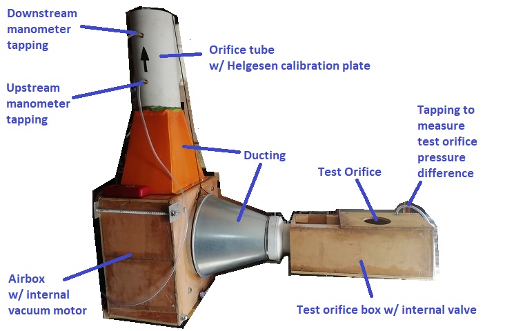
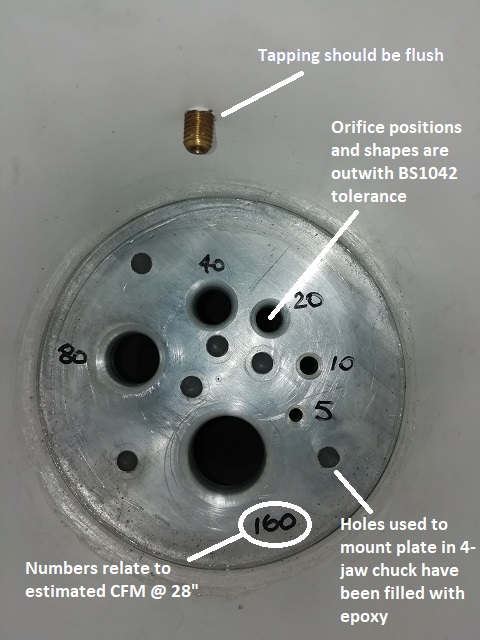
View of Helgesen calibration plate (upstream side visible, downstream side has sharp edges)...
View of internal valve...
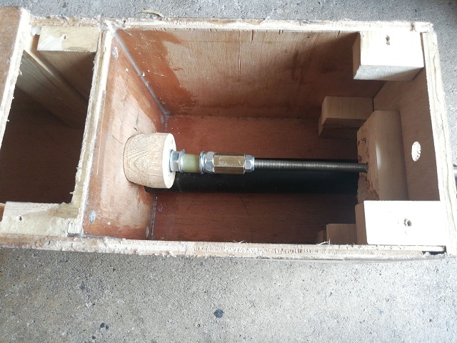
[It's purpose is maintain a known pressure drop (usually 28" H2O) inside the test orifice box.]
Modifications Required
1. The orifice plate(s) need to conform to the dimensions in Method 7 of the standard.
2. The orifice plate tube needs to conform to the dimensions in Method 6 of the standard.
Link to flow bench program thread
...BS 1042 Part 1 Section 1.1
I've already made some serious changes to my flow bench - a complete redesign. Having read the standard, I now have to make some changes to the orifice plate tube (the white tube with the arrow). I should have searched harder for the document when Mignon advised me
Current setup...
View of Helgesen calibration plate (upstream side visible, downstream side has sharp edges)...
View of internal valve...
[It's purpose is maintain a known pressure drop (usually 28" H2O) inside the test orifice box.]
Modifications Required
1. The orifice plate(s) need to conform to the dimensions in Method 7 of the standard.
2. The orifice plate tube needs to conform to the dimensions in Method 6 of the standard.
Link to flow bench program thread
Edited by pingu393 on Friday 19th October 23:22
Edited by pingu393 on Tuesday 6th November 11:12
The following posts are mainly for my benefit and are the algorithms inside the Excel spreadsheet that I use to calculate the volume flow rate.
The standard that I have based the spreadsheet on is ISO 5167
ISO 5167 Spreadsheet
The standard that I have based the spreadsheet on is ISO 5167
ISO 5167 Spreadsheet
[Air Pressure Equations]
Temp in °F = (9*B4/5)+32
[B4 = Temp in °C]
Height in Feet = B5*3.28084
[B5 = height in metres]
Pressure in inches of Hg = B6*0.02953
[B6 = pressure in mBar (measured on a "sea-level" calibrated barometer]
Latitude in radians = B8*PI()/180
[B8 = latitude in degrees]
Temperature in Rankin = B9+459.67
[B9 = temperature in Farenheit]
Latitude-corrected pressure = B11*((-0.002637*COS(2*B12))+(0.000006*(COS(2*B12))^2)-0.00005)
[B11 = pressure in inches of Hg]
[B12 = latitude in Radians]
Temperature-corrected pressure = B11*((B14-28.63)/((1.1123*B14)+10978))
[B11 = pressure in inches of Hg]
[B14 = temperature in Farenheit]
Altitude-corrected pressure = -29.92126*(1-(1/(10^((0.008135*B10)/((B13+(0.00178308*B10)))))))
[B10 = height in feet]
[B13 = temperature in Rankin]
Total corrected pressure in inches of Hg = B15+B16+B17
[B15 = Latitude-corrected pressure]
[B16 = Temperature-corrected pressure]
[B17 = Altitude-corrected pressure]
Actual pressure in mBar = (B11+B19)*33.8637526
[B11 = pressure in inches of Hg]
[B19 = Total corrected pressure in inches of Hg]
[Air Density Calculations]
Ambient Temperature in Kelvin = B3+273.15
[B3 = Ambient temperature in Celcius]
Pv = 100*(B8+B6*(B9+B6*(B10+B6*(B11+B6*(B12+B6*(B13+B6*(B14+B6*(B15+B6*(B16+B6*(B17))))))))))
[Pv = Vapour pressure in mBar]
[B6 = Dew Point Temperature in Celcius]
[B8 = 0.99999683]
[B9 = -0.0090826951]
[B10 = 0.000078736169]
[B11 = -0.00000061117958]
[B12 = 0.0000000043884187]
[B13 = -0.000000000029883885]
[B14 = 2.1874425E-13]
[B15 = -1.7892321E-15]
[B16 = 1.1112018E-17]
[B17 = -3.0994571E-20]
Pd = 100*(B5-B18)
[Pd = Dry pressure in Pascals (or N/sq m)]
[B5 = Corrected ambient pressure in mBar]
[B18 = Pv (Vapour pressure in mBar)]
Air Density in kg/cu m = (B23/(B26*B27))+(B19/(B25*B27))
[B19 = Pv = Vapour pressure in mBar]
[B23 = Pd = Dry pressure in Pascals (or N/sq m)]
[B25 = 461.4964]
[B26 = 287.0531]
[B27 = Ambient temperature in Kelvin]
[Temperature-Adjusted Orifice Dimension Calculations]
Pipe/Bore Diameter = ((C4*10^(-3))*(1+((C24*10^(-6))*(C17-C3))))*1000
[C3 = Temperature at Measuring Station in Celcius]
[C4 = Bore diameter in mm (as measured)]
[C17 = temperature at upstream tapping plane in Celcius]
[C24 = coefficient of thermal expansion in micrometres/metre Kelvin]
Orifice diameter = ((C5*10^(-3))*(1+((C24*10^(-6))*(C17-C3))))*1000
[C3 = Temperature at Measuring Station in Celcius]
[C5 = Orifice diameter in mm (as measured)]
[C17 = temperature at upstream tapping plane in Celcius]
[C24 = coefficient of thermal expansion in micrometres/metre Kelvin]
Distance to Upstream Tapping Plane = ((C8*10^(-3))*(1+((C24*10^(-6))*(C17-C3))))*1000
[C3 = Temperature at Measuring Station in Celcius]
[C8 = Distance from Upstream face of orifice plate to the upstream tap in mm (as measured)]
[C17 = temperature at upstream tapping plane in Celcius]
[C24 = coefficient of thermal expansion in micrometres/metre Kelvin]
Distance to Downstream Tapping Plane = ((C9*10^(-3))*(1+((C24*10^(-6))*(C17-C3))))*1000
[C3 = Temperature at Measuring Station in Celcius]
[C9 = Distance from Upstream face of orifice plate to the downstream tap in mm (as measured)]
[C17 = temperature at upstream tapping plane in Celcius]
[C24 = coefficient of thermal expansion in micrometres/metre Kelvin]
Diameter Ratio (Beta) = I8/I7
[I7 = Temperature-adjusted bore diameter]
[I8 = Temperature-adjusted orifice diameter]
Relative Upstream Tap Ratio (L1) = I9/I7
[I7 = Temperature-adjusted bore diameter]
[I8 = Temperature-adjusted distance to upstream tapping plane]
Relative Downstream Tap Ratio (L2) = I10/I7
[I7 = Temperature-adjusted bore diameter]
[I8 = Temperature-adjusted distance to downstream tapping plane]
Expansion Factor (Epsilon) = 1-((0.351+(0.256*(I11^4)+(0.93*(I11^8))))*(1-(C22/C16)^(1/C26)))
[I11 = Diameter Ratio]
[C16 = upstream pressure]
[C22 = downstream pressure (must be the same units as C16)]
[C26 = isentropic component at upstream tap temperature]
Approach Velocity = (1-(I11^4))^(-0.5)
[I11 = Diameter Ratio]
M2 (this is a constant used in the calculation of the discharge coefficient) = (2*I13)/(1-I11)
[I11 = Diameter Ratio]
[I13 = Relative Downstream Tap Ratio]
[Reynold's Number Calculations]
For the first iteration of
Reynold's Number --> Discharge Coefficient --> Mass Flow Rate
use Reynold's Number = 1000000
For all other iterations...
Reynold's Number = (4*C2)/(PI()*(C3/1000)*C4)
[C2 = Mass flow rate in kg/s]
[C3 = Bore diameter in mm]
[C4 = Dynamic viscosity at upstream temperature in N-s/sq m]
Edited by pingu393 on Saturday 17th November 14:39
[Discharge Coefficient Calculations]
Alpha = (19000*C4/C9)^0.8
[C4 = Diameter Ratio]
[C9 = Reynold's Number]
Discharge Coefficient (C) = B13+B14+B15+B16+B17+B18+B19+B20
[C3 = Bore diameter in mm]
[C4 = Diameter Ratio]
[C9 = Reynold's Number]
[C7 = Upstream Tap Ratio]
[C10 = Alpha]
[C11 = M2] - see "Dimensions and Readings"
[B13 = 0.5961]
[B14 = 0.0261*C4^2]
[B15 = -0.216*C4^8]
[B16 = 0.000521*(1000000/C9)^0.7]
[B17 = (0.0188+0.0063*C10)*(C4^3.5)*((1000000/C9)^0.3)]
[B18 = (0.043+(0.08*EXP(-10*C7))-(0.123*EXP(-7*C7)))*(1-0.11*C10)*((C4^4)/(1-(C4^4)))]
[B19 = -0.031*(C11-0.8*(C11^1.1))*(C4^1.3)]
[B20 = 0.011*(0.75-C4)*(2.8-(C3/25.4))
[Mass Flow Rate Calculations]
Delta P in N/sq m = C4*9.80638
[C4 = Difference between upstream and Downstream pressure in mm H2O]
Mass Flow Rate in kg/s =C23*I15*I14*(PI()/4)*((C2/1000)^2)*(2*C5*C3)^0.5
[C2 = Orifice diameter in mm]
[C3 = Air density im kg/cu m]
[C5 = Delta P]
[C23 = Discharge Coefficient]
[I14 = Expansion Factor]
[I15 = Approach Velocity Factor]
[Final Sheet Calculations]
Test Orifice Depression in inches H2O = C3/25.4
[C3 = Test orifice depression in mm H2O]
Volume Flow Rate in CFM = (C7/C2)*2118.88
[C2 = Ambient Air Density]
[C7 = Mass Flow Rate]
Volume Flow Rate Equivalent @ 10" H2O = C6*(10/C4)^0.5
[C6 = Volume flow rate at test orifice pressure difference]
[C4 = Test orifice pressure difference]
Volume Flow Rate Equivalent @ 25" H2O = C6*(25/C4)^0.5
[C6 = Volume flow rate at test orifice pressure difference]
[C4 = Test orifice pressure difference]
Volume Flow Rate Equivalent @ 28" H2O = C6*(28/C4)^0.5
[C6 = Volume flow rate at test orifice pressure difference]
[C4 = Test orifice pressure difference]
AW111 said:
Is there a reason you're converting everything to hogsheads and roods instead of sticking to SI units?
I always convert speed into miles per hour, and fuel consumption into miles per gallon. Flow rate is much the same, I think of it in cubic feet per minute.As for the calculations inside the spreadsheet, a lot of them were reverse-engineered from the internet. As the originals were in imperial, it was easier to do the calculations in imperial.
The inputs are SI, or the most commonly used unit (mm H2O, mBar, mm, °C). What happens inside the calculation doesn't matter to the user (much like an engine).
Mignon said:
I'm not sure why you're posting all these equations. Do you want someone to check them all?
An easier question might be have you actually found any errors in my own spreadsheet? If not then yours is right when it agrees with mine.
The main reason for posting was to put them somewhere safe. At least as safe as Pistonheads An easier question might be have you actually found any errors in my own spreadsheet? If not then yours is right when it agrees with mine.
Edited by Mignon on Sunday 18th November 05:12
.Anyone who wants to check them, please feel free.
They will never agree exactly with your results as your equation for the discharge coefficient is based on Stolz. This one is based on Reader-Harris/Gallagher. Both spreadsheets produce the same answer to within a few decimal points of CFM on the data you posted. That should be good enough for any sensible engineer.
This set of equations assumes a D / D/2 arrangement for the taps. I think that yours assumes flange taps.
The only "fault" that I found in your spreadsheet was in how to use it. It was not a fault in the algorithms, but there was a circular reference on the Reynold's Number. The amendment that I made to your sheet was to add a cell where you manually update the Reynold's Number. This removed the circular reference. Just adjust the Reynold's Number until the updated Reynold's Number = the adjusted Reynold's Number.
Mignon said:
The circular reference was there on purpose you numpty. You just keep pressing "calc" and the Reynolds Number works itself out automatically.
A circular reference is an instant fail on every computing course I've ever done. It's not something a numpty like me was expecting to be deliberate.Gassing Station | Home Mechanics | Top of Page | What's New | My Stuff