Full circle into a Marina again. My 73 Morris Marina Coupe
Discussion


anonymous said:
[redacted]
Thats a solid theory, but I do wish it was a bit brighter so I could see when I accidentally leave the high beam on when it isn't dark.Its also interesting to note that all my wiring diagrams, and owners manual, say the high beam indicator light should be at the bottom of the speedo, not the top of the aux dials. The light a the bottom of the speedo does nothing, and is red. There is mention it might be a brake warning lamp of some sort, probably in the higher spec models.
Typically, being sat for 25 odd years, none of the hydraulics work. The clutch pedal is solid, and the brake pedal goes to the floor, and both do nothing to their respective components.
I removed and stripped the clutch master and slave a while back, just to see what was going on. The slave was definitely seized, as using a long prybar on the clutch fork to compress the slave resulted in a sudden BANG and it started to move freely. I still needed to remove it to inspect though, as it was obviously getting hung up on something.
The Aussies are a bit smarter than the Brits with the slave cylinder. The UK cars you need to remove the clutch line, remove the clutch pin, and then try to slide the cylinder towards the rear of the car, and get it out from between its housing and the clutch fork. Sometimes this is easy, other times it requires a special tool to push the clutch fork back to create space. The Aus cars have a circlip to secure the slave, so once that and the clutch line is removed, the slave slides towards the front of the car, where there is ample space to remove it. In fact, one of the UK manuals I have claims the slave can ONLY be removed if the gearbox is removed from the car!
UK cars

And Aus cars

With the slave removed and on the bench, I removed the pushrod pin and boot. You can see the rusty sludge that the piston has moved.

After I cleaned the sludge out of the holes in the circlip and removed it, the guts of the cylinder came out with some prodding.

Everything actually looked reasonably good, with minimal signs of rust in the bore. There was some at the very front, which a quick touch up with fine sandpaper fixed no issue. I'll be reusing this slave, but have a new seal kit for it. I could have gotten away with reusing the existing seal, it looked fine, but don't want to do the job twice for the sake of a few quid. That kit arrived the other day, so will rebuild that soon.
The master on the other hand is a write off.
I removed it from the car, removed the pushrod, and thats as far as I can go

No amount of "gently tapping" will force that piston out. I ended up putting about 70PSI behind it, and only got this far
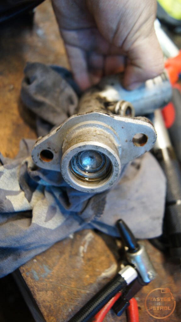
I can only presume the piston and/or the bore is rusty and just binding. It turns out this is a Spitfire master cylinder, so have ordered a complete replacement and will fit that when it arrives.
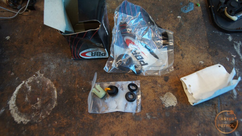
Moving along, I started work on the brakes. This work was proceeded by buying some basic parts and finding some in the boot. I purchased all new hoses for the front and rear. The fronts are from a Series 3 Land Rover (2x BR0764) and the rear is from a Triumph Spitfire (1x GBH166). I found a new old stock master cylinder rebuild kit in the boot, purchased new in Tokoroa in 2001.

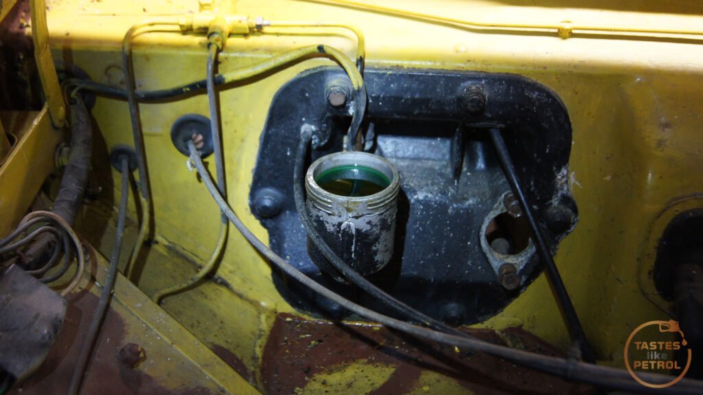
I had previously tried to bleed the system but got zero fluid from any of the bleed nipples, even when trying to draw the fluid through under vacuum. There was fluid in the reservoir when I got the car, but it was a bit low, so I thought I would top it off before trying to draw it through. Pouring in dot4 resulted in the weirdest "mixing" I've seen. The fluid kinda floated around and when it slowly mixed it kinda sparkled and didn't look right. I sucked the fluid out, and sure enough, I'm 90% sure the master cylinder was filled with engine oil. It smelt like clean engine oil. Even sucking it all out left some sludge in the bottom of the reservoir.

This was a bit easier to strip down. A few hard bashes on the vice and the piston popped out, covering my hand in whatever sludge was in the bore, chunks and all.

I was trying to think of why you would fill the reservoir with oil and the only reason I could come up with was to stop the bore rusting. Well, it didn't. With the piston removed, there was some minor rust on the sides of the bore, but bad rust and pitting at the very end, where the seal on the end needs to block the reservoir. I cleaned it up as much as I could. The rust on the sides of the bore wiped off with some fine sandpaper.

The piston had some light corrosion on it, but looked OK otherwise.

This is the end seal, you can see all the crud built up around it

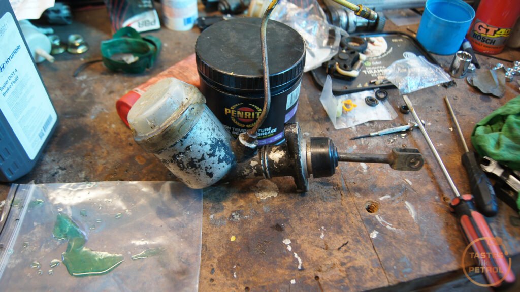
The seals weren't too bad, but having the new kit already I swapped them all over and reassembled. A quick test on the bench showed that it seemed to be working as it should, so I reinstalled it into the car.
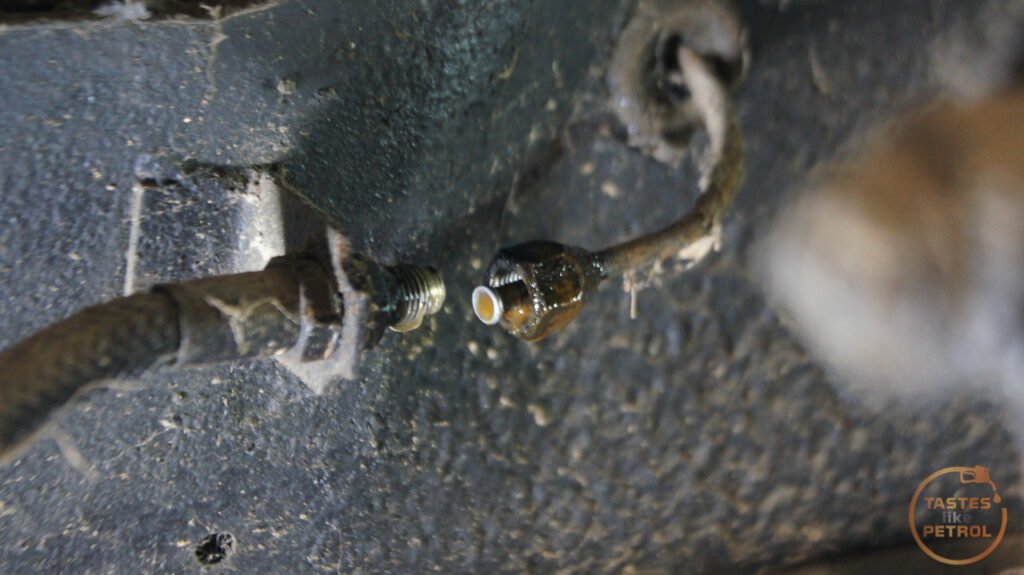
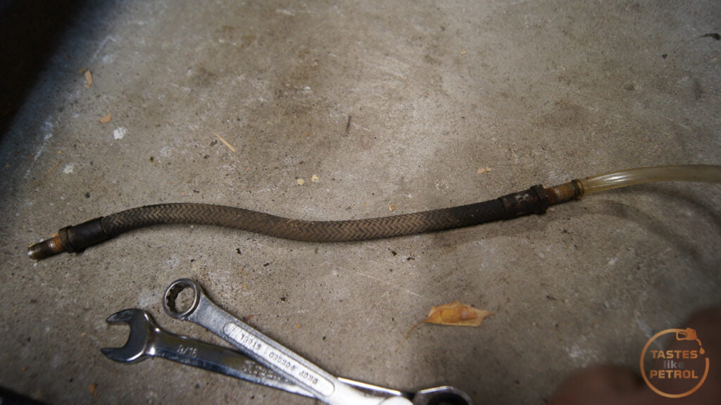
Now it was time to work on the hoses and calipers. I started on the front. The hoses came off reasonably easily. With the hose disconnected from the hard line I attached my vacuum bleeder to suck through fluid and flush the line. I like using the green fluid as it's really obvious when the new fluid is coming through.
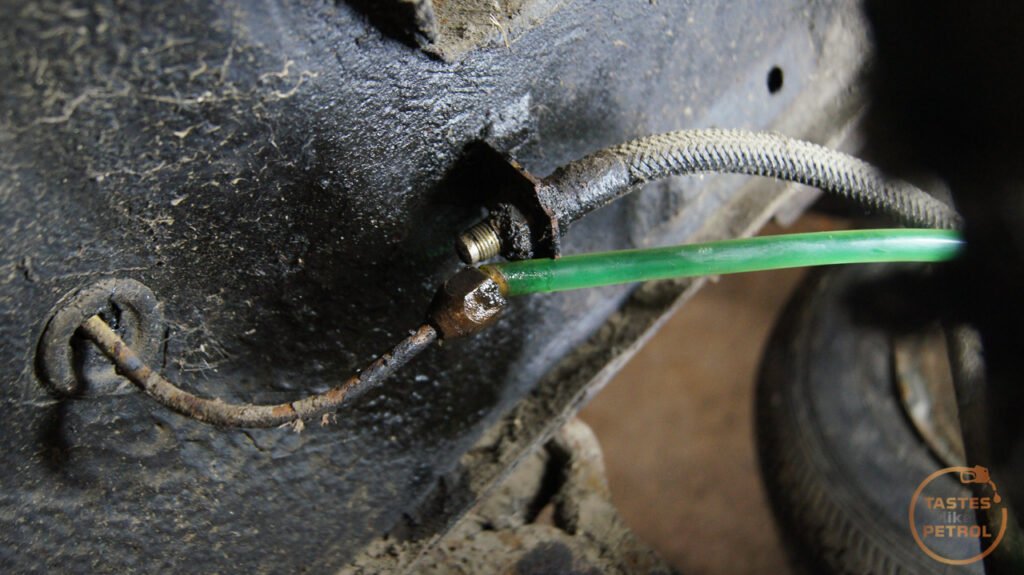
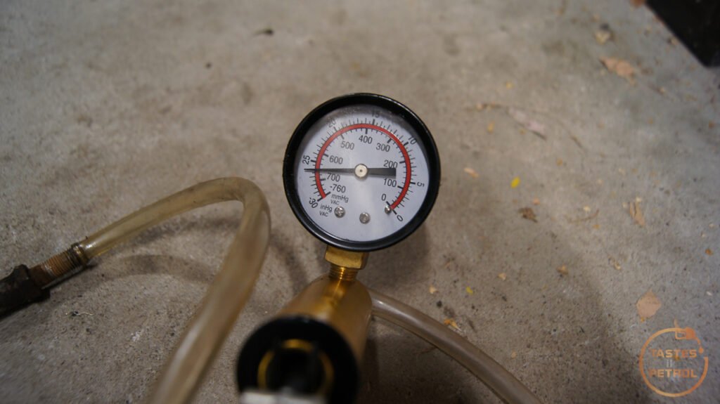
Out of curiosity, once I removed the hose I connected the vac pump up to one end, left the other end open and tried to pull air through it. Nothing. Blocked solid, and even with the most suction that pump can draw, not a single drop of air could get through.

I was warned about these style hoses, the old style with that textured outer layer, when I redid the hoses on the TVR. The rear hose on the TVR was of this style, and apparently they are known for internally degrading and blocking up over time. The other side was the same, completely blocked.
The new Land Rover pattern hoses look nice enough

I temporarily reconnected the old hose to the hard line, just to block the end of it in the mean time so I can draw a vacuum from the reservoir.
The other side had some questionable looking fluid in the lines, but flushed OK.
With the hoses off I began removing the calipers. I'm glad I previously vacuumed most of the cobwebs off. Ugh.

These were well stuck on, but some hammering and levering saw them jump off the rotor. I'm hoping the rotors will clean up OK, will need to check their thickness.

Everything looked and felt like it had been on there far too long. Even removing the pad retaining pins was a pain, but lots of hammering and lots of CRC got them out.

The previous owner got their monies worth from the pads.
One of the piston boots was missing its retaining clip, and was just floating around.

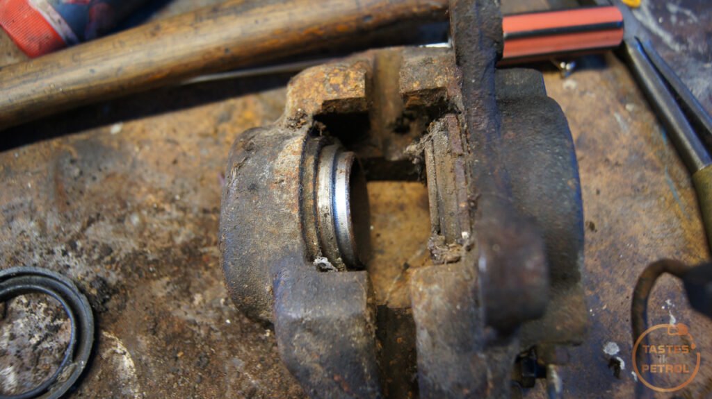
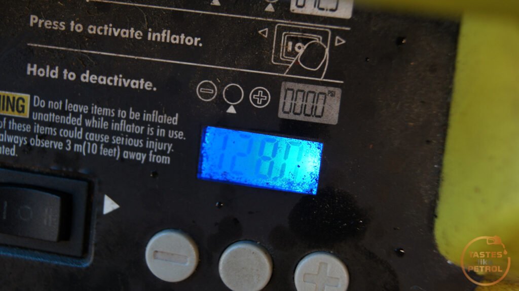
I had to get creative to try and force the pistons out. One is moving freely, but one is jammed solid. Even 128psi couldnt shift it. I'll need to try and shock it with my actual air compressor, not slowly build pressure with the tyre inflator.

The other caliper isn't much better, neither piston felt like moving on that one.

The one piston I did get out was a disappointment though, the chrome coating is flaking off in places and there is scoring and corrosion on it, so all the pistons will need to be replaced. I already have a seal kit, but will wait on new pistons now. Might even paint the calipers in the meantime to make them flashy (even if you can see them with the wheels on).
The last job for the day was to remove the rear hose. There is only one, as the fluid goes to the RH side wheel cylinder and then crosses over to the LH side one. Another old textured hose.

New hose partly connected. I'm pleased at hose easily these old hoses came off. A ratcheting spanner certainly helps for the lock nut though.

And new hose installed.

Another quick test with the vac pump, and sure enough, another completely blocked hose
Pays to check your hoses and replace them if they are the old style.
With the new hose in place, the only other thing to do was flush the lines with new fluid. There was quite a bit of fluid in the cylinders and lines. Didn't look too bad, and no rust, so hopefully that means the rear wheel cylinders are still OK. I can get the kits to rebuild them locally, so will see if they work first and go from there.

And keep pulling it through until it goes green

Unfortunately I tried pumping the pedal with the system all buttoned up, and the master cylinder is blowing fluid back into the reservoir, indicating the end seal isn't sealing. I have reached out to a couple of companies that should be able to sleeve the cylinder and will see what they say.
In the mean time, off to make a list of more parts I need to buy.
I removed and stripped the clutch master and slave a while back, just to see what was going on. The slave was definitely seized, as using a long prybar on the clutch fork to compress the slave resulted in a sudden BANG and it started to move freely. I still needed to remove it to inspect though, as it was obviously getting hung up on something.
The Aussies are a bit smarter than the Brits with the slave cylinder. The UK cars you need to remove the clutch line, remove the clutch pin, and then try to slide the cylinder towards the rear of the car, and get it out from between its housing and the clutch fork. Sometimes this is easy, other times it requires a special tool to push the clutch fork back to create space. The Aus cars have a circlip to secure the slave, so once that and the clutch line is removed, the slave slides towards the front of the car, where there is ample space to remove it. In fact, one of the UK manuals I have claims the slave can ONLY be removed if the gearbox is removed from the car!
UK cars
And Aus cars
With the slave removed and on the bench, I removed the pushrod pin and boot. You can see the rusty sludge that the piston has moved.
After I cleaned the sludge out of the holes in the circlip and removed it, the guts of the cylinder came out with some prodding.
Everything actually looked reasonably good, with minimal signs of rust in the bore. There was some at the very front, which a quick touch up with fine sandpaper fixed no issue. I'll be reusing this slave, but have a new seal kit for it. I could have gotten away with reusing the existing seal, it looked fine, but don't want to do the job twice for the sake of a few quid. That kit arrived the other day, so will rebuild that soon.
The master on the other hand is a write off.
I removed it from the car, removed the pushrod, and thats as far as I can go
No amount of "gently tapping" will force that piston out. I ended up putting about 70PSI behind it, and only got this far
I can only presume the piston and/or the bore is rusty and just binding. It turns out this is a Spitfire master cylinder, so have ordered a complete replacement and will fit that when it arrives.
Moving along, I started work on the brakes. This work was proceeded by buying some basic parts and finding some in the boot. I purchased all new hoses for the front and rear. The fronts are from a Series 3 Land Rover (2x BR0764) and the rear is from a Triumph Spitfire (1x GBH166). I found a new old stock master cylinder rebuild kit in the boot, purchased new in Tokoroa in 2001.
I had previously tried to bleed the system but got zero fluid from any of the bleed nipples, even when trying to draw the fluid through under vacuum. There was fluid in the reservoir when I got the car, but it was a bit low, so I thought I would top it off before trying to draw it through. Pouring in dot4 resulted in the weirdest "mixing" I've seen. The fluid kinda floated around and when it slowly mixed it kinda sparkled and didn't look right. I sucked the fluid out, and sure enough, I'm 90% sure the master cylinder was filled with engine oil. It smelt like clean engine oil. Even sucking it all out left some sludge in the bottom of the reservoir.
This was a bit easier to strip down. A few hard bashes on the vice and the piston popped out, covering my hand in whatever sludge was in the bore, chunks and all.
I was trying to think of why you would fill the reservoir with oil and the only reason I could come up with was to stop the bore rusting. Well, it didn't. With the piston removed, there was some minor rust on the sides of the bore, but bad rust and pitting at the very end, where the seal on the end needs to block the reservoir. I cleaned it up as much as I could. The rust on the sides of the bore wiped off with some fine sandpaper.
The piston had some light corrosion on it, but looked OK otherwise.
This is the end seal, you can see all the crud built up around it
The seals weren't too bad, but having the new kit already I swapped them all over and reassembled. A quick test on the bench showed that it seemed to be working as it should, so I reinstalled it into the car.
Now it was time to work on the hoses and calipers. I started on the front. The hoses came off reasonably easily. With the hose disconnected from the hard line I attached my vacuum bleeder to suck through fluid and flush the line. I like using the green fluid as it's really obvious when the new fluid is coming through.
Out of curiosity, once I removed the hose I connected the vac pump up to one end, left the other end open and tried to pull air through it. Nothing. Blocked solid, and even with the most suction that pump can draw, not a single drop of air could get through.
I was warned about these style hoses, the old style with that textured outer layer, when I redid the hoses on the TVR. The rear hose on the TVR was of this style, and apparently they are known for internally degrading and blocking up over time. The other side was the same, completely blocked.
The new Land Rover pattern hoses look nice enough
I temporarily reconnected the old hose to the hard line, just to block the end of it in the mean time so I can draw a vacuum from the reservoir.
The other side had some questionable looking fluid in the lines, but flushed OK.
With the hoses off I began removing the calipers. I'm glad I previously vacuumed most of the cobwebs off. Ugh.
These were well stuck on, but some hammering and levering saw them jump off the rotor. I'm hoping the rotors will clean up OK, will need to check their thickness.
Everything looked and felt like it had been on there far too long. Even removing the pad retaining pins was a pain, but lots of hammering and lots of CRC got them out.
The previous owner got their monies worth from the pads.
One of the piston boots was missing its retaining clip, and was just floating around.
I had to get creative to try and force the pistons out. One is moving freely, but one is jammed solid. Even 128psi couldnt shift it. I'll need to try and shock it with my actual air compressor, not slowly build pressure with the tyre inflator.
The other caliper isn't much better, neither piston felt like moving on that one.
The one piston I did get out was a disappointment though, the chrome coating is flaking off in places and there is scoring and corrosion on it, so all the pistons will need to be replaced. I already have a seal kit, but will wait on new pistons now. Might even paint the calipers in the meantime to make them flashy (even if you can see them with the wheels on).
The last job for the day was to remove the rear hose. There is only one, as the fluid goes to the RH side wheel cylinder and then crosses over to the LH side one. Another old textured hose.
New hose partly connected. I'm pleased at hose easily these old hoses came off. A ratcheting spanner certainly helps for the lock nut though.
And new hose installed.
Another quick test with the vac pump, and sure enough, another completely blocked hose
Pays to check your hoses and replace them if they are the old style.
With the new hose in place, the only other thing to do was flush the lines with new fluid. There was quite a bit of fluid in the cylinders and lines. Didn't look too bad, and no rust, so hopefully that means the rear wheel cylinders are still OK. I can get the kits to rebuild them locally, so will see if they work first and go from there.
And keep pulling it through until it goes green
Unfortunately I tried pumping the pedal with the system all buttoned up, and the master cylinder is blowing fluid back into the reservoir, indicating the end seal isn't sealing. I have reached out to a couple of companies that should be able to sleeve the cylinder and will see what they say.
In the mean time, off to make a list of more parts I need to buy.
jamesson said:
This is great work. I wish I had a fraction of your talent. Looking forward to further updates in due course.
I believe most people with an interest in working on cars should be able to do most of what I do, it's just a matter of being methodical, and it always helps to read the workshop manual cover to cover a few times. I'm not a mechanic, have no training, and didn't grow up around cars.bolidemichael said:
Wait, what?!
I'm sorry, but the breadth of your knowledge and know how - cracking the issue of the TVR's K-Jet (iirc) system and diagnosing the cack-handedness of previous bodges. That was all brilliant stuff and so detailed. You're bluffing us just because we're in Blighty and can't throw tomatoes at you. Right?
Nope, not kidding. The only qualification I have is to fix Apple computers (which I haven't done for years) I'm sorry, but the breadth of your knowledge and know how - cracking the issue of the TVR's K-Jet (iirc) system and diagnosing the cack-handedness of previous bodges. That was all brilliant stuff and so detailed. You're bluffing us just because we're in Blighty and can't throw tomatoes at you. Right?
 Otherwise, I tanked at school and dropped out early.
Paul S4 said:
A few years ago I had a 1970 lotus Elan S4SE drophead that had been in the family, and was completely restored by my late Uncle.
I had that car for over 12 years, and in the time I did quite a lot of work on it...so i got to know the underside quite well...!
Anyway, the clutch slave cylinder was very similar to your Marina set up, so it was easy to replace as it had the same circlip arrangement. On my car it was very close to the stainless exhaust system, which got very hot ( that car was driven as Colin Chapman intended !!) and over time the heat got to the slave so I had to change it a few times. I also replaced the hard steel line with an aftermarket braided stainless steel one, which helped with the clutch action...somehow !
I also recall the the first time I had clutch issues after I took over custodianship of the Elan, I changed the clutch fluid and it was just a black goo.... I reckon that the rubber seals had gone.
Anyway, just thought I would add this out of interest as Lotus used a lot of parts from other car companies.....in that sense the Elan was a 'kit car'...in fact 80% of them were sold as self assembly kits to save the "Purchase Tax" of the time, so that explains why there is a lot of difference in the way some of those cars have been put together !!
Apologies for going off topic....
Gosh that sounds an awful lot like the TVR; bits of other cars thrown together and not always in the best design. Sounds like a heatshield might have helped with that issue.I had that car for over 12 years, and in the time I did quite a lot of work on it...so i got to know the underside quite well...!
Anyway, the clutch slave cylinder was very similar to your Marina set up, so it was easy to replace as it had the same circlip arrangement. On my car it was very close to the stainless exhaust system, which got very hot ( that car was driven as Colin Chapman intended !!) and over time the heat got to the slave so I had to change it a few times. I also replaced the hard steel line with an aftermarket braided stainless steel one, which helped with the clutch action...somehow !
I also recall the the first time I had clutch issues after I took over custodianship of the Elan, I changed the clutch fluid and it was just a black goo.... I reckon that the rubber seals had gone.
Anyway, just thought I would add this out of interest as Lotus used a lot of parts from other car companies.....in that sense the Elan was a 'kit car'...in fact 80% of them were sold as self assembly kits to save the "Purchase Tax" of the time, so that explains why there is a lot of difference in the way some of those cars have been put together !!
Apologies for going off topic....
Pistons are out. The fluid that was behind them was disgusting. There was also a buildup in the lowest point of the caliper which I had to chip out during cleaning.

This pitting is what I was up against. It was grabbing the seal for dear life. Used a combo of air from my compressor, whilst beating the heck out of the piston with a punch in the direction of removal to get them out.

The calipers cleaned up alright after a dip in the parts washer. Now sitting in a bath of Evaporust to clean any rust out.

Waiting on the new pistons to arrive and then I'll rebuild the calipers.
This pitting is what I was up against. It was grabbing the seal for dear life. Used a combo of air from my compressor, whilst beating the heck out of the piston with a punch in the direction of removal to get them out.
The calipers cleaned up alright after a dip in the parts washer. Now sitting in a bath of Evaporust to clean any rust out.
Waiting on the new pistons to arrive and then I'll rebuild the calipers.
I refurbished the rear drum brake setup today. I almost left it as is, but I'm glad I didn't as it definitely needed stripping down.
I removed the drums a while back and had a quick visual inspection, and whilst one side looked like it had been under the ocean, there was no brake fluid or axle grease where it shouldn't be.

I started on the LH side, which didn't look like it had been under the sea, but instead had been full of bugs and spiders. The whole drum was packed with cobwebs and took a lot of cleaning and vacuuming to not be grossed out.

The shoes look really good, almost new I'd say, and everything was very dry. Someone had been in here before though as this big, annoying to install, spring should be behind the shoes, not in front of them.
Removing the shoes is a case of removing the little retaining spring pins, removing the big spring and then the pair of shoes can be withdrawn from the backing plate.
With the shoes out the cylinder can be removed by undoing the pipe(s), removing the boot, sliding the U shaped clip downwards and the spring clip upwards. The cylinder should be free to remove.

This one looked OK. The boot was torn, and the piston had some crud built up on it, but the bore was clean. The piston seal looked so good I probably could have reused it, but since I ordered a replacement seal kit anyway, I replaced it. The seal kit for this car is from a Spitfire and has 3/4" (19.05mm) bore.


With the build up carefully scraped off and polished with some fine sandpaper, the new piston seal goes on.

Now, before installing the piston in the cylinder again, install the boot first. This is a real prick of a job as it needs to stretch over the top, and it's a very tight fit.

And carefully install back into the cylinder. I chose to lube the cylinder walls and piston/seal with brake fluid for assembly.

Reinstall the clip and you're done.

There isn't a heck of a lot to a wheel cylinder on these.
I cleaned up and greased the self-adjuster. This just rests in the bottom of the cylinder but must turn freely.

Now clean the backing plate up, especially at the points where the cylinder and shoes contact it (the six raised bumps on the top and bottom, as well as the anchor where the end of the shoes rest and behind the wheel cylinder). I used a wire brush and brake clean. Once clean, use thin smears of copper or brake grease on those contact points.

Once the cylinder and hand brake lever is installed, reinstall the shoes. I found this easiest with the double spring in one end (shoe end), rest the top shoe on the hub, whilst inserting the lower shoe into the self-adjuster and then the shoe anchor. Now the top shoe can be installed. Take care not to lose the little metal H piece that sits above the handbrake lever where it goes through the shoe.
Don't forget to install the retaining pins and the big spring. As mentioned, this should be behind the shoes, and I found levering it in place with a long flat blade screwdriver easiest. It takes a few tries.

Done.

Rebuilt cylinder
So cocky, on went the drum

Now to move onto the other side.
This one was very crusty. Obviously water had gotten into the drum somehow, and couldn't get out until it dried over time. This drum had plugs in the adjuster holes, whilst the other side didn't. Explains why the bugs liked that side, and the water got stuck in this side.

The cylinder on this side was looking particularly average.

Removing the shoes shows how crusty it was

The adjuster was completely seized. No chance of self-adjustment here. Just as an aside, the self-adjustment works by means of pulling on the hand brake. Pulling the hand brake pulls up on the top shoe, creating the friction to stop the car, but the movement of that lever also moves the metal tang in the photo below from left to right. As it heads on over to the right it catches the teeth of the adjuster, which winds the threaded inner section that the lower shoe rests on up and down. The whole cylinder is free to move up and down in its mount, which evens out the braking between the two shoes. Simple.

Removing the cylinder on this side was a little more of a pain as it has the inlet and the link pipe, instead of just the inlet and a bleeder like the other side. Both freed off with some careful force, and out came the cylinder.

The adjuster came off the end after a couple of careful taps with a hammer. It was packed with furry corrosion behind it.

As was the space under the boot on the top. This concerned me a bit as it didn't bode well for the condition of the bore.

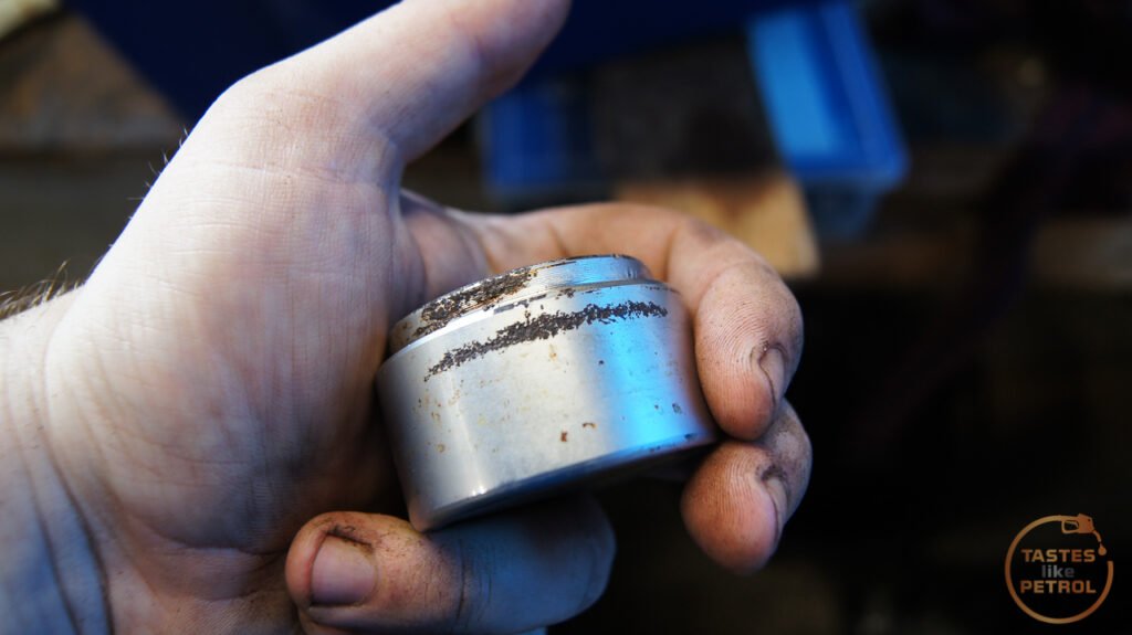
The piston is completely compressed and didn't move by hand

It did move with some gentle persuasion with a long screwdriver though


I had to get a bit more angry to get it out further. A long spanner was used as the lever for this

And out it popped

The bore looks worse than it is. The cylinder is aluminium, so it's not really rust, just a build up of gunk stuck to the bore. I suspect the piston is stainless as other than more gunk on it, it was immaculate. The seal on the other hand was rubbish as there is a big tear/cut in it.

Mmm, more crusty fur

I tidied the bore up with some careful scraping, and then some very fine sandpaper. There is some staining on the walls, but there are no marks you can feel. The walls are very smooth.

The rest of the cylinder got scraped and wire brushed before a good clean out and the new seal kit fitted.

Before refitting, the back plate was de-crusted with a wire brush and then brake clean.

The cylinder was refitted. The locking method for these is a bit of a pain, but simple enough. The spring clip goes down from the top first, with the dimples pointing outwards (away from the cylinder). The locking U shaped clip then slides up over top of the spring clip, and locks into the dimples. I used a flat blade screwdriver to press down on the top of the spring clip, and pliers to tap up on the U clip.

And the wheel cylinder is in.

The shoes got a quick scuff with some rough sandpaper to clean the surface up a bit, and then they were fitted. They look fine but had some rust marks where they had been in contact with the drum.

And the completed assembly

The friction surface on the drum was quite rusty too, so that got a wire brush before fitting. It's good enough that any other rust should be scraped off once the car is on the road and the brakes operate.

Drum fitted

Unfortunately I can't test them as the master cylinder is off being re-sleeved, and the front brakes also need to go back on, but hopefully it won't be long.
I removed the drums a while back and had a quick visual inspection, and whilst one side looked like it had been under the ocean, there was no brake fluid or axle grease where it shouldn't be.
I started on the LH side, which didn't look like it had been under the sea, but instead had been full of bugs and spiders. The whole drum was packed with cobwebs and took a lot of cleaning and vacuuming to not be grossed out.
The shoes look really good, almost new I'd say, and everything was very dry. Someone had been in here before though as this big, annoying to install, spring should be behind the shoes, not in front of them.
Removing the shoes is a case of removing the little retaining spring pins, removing the big spring and then the pair of shoes can be withdrawn from the backing plate.
With the shoes out the cylinder can be removed by undoing the pipe(s), removing the boot, sliding the U shaped clip downwards and the spring clip upwards. The cylinder should be free to remove.
This one looked OK. The boot was torn, and the piston had some crud built up on it, but the bore was clean. The piston seal looked so good I probably could have reused it, but since I ordered a replacement seal kit anyway, I replaced it. The seal kit for this car is from a Spitfire and has 3/4" (19.05mm) bore.
With the build up carefully scraped off and polished with some fine sandpaper, the new piston seal goes on.
Now, before installing the piston in the cylinder again, install the boot first. This is a real prick of a job as it needs to stretch over the top, and it's a very tight fit.
And carefully install back into the cylinder. I chose to lube the cylinder walls and piston/seal with brake fluid for assembly.
Reinstall the clip and you're done.
There isn't a heck of a lot to a wheel cylinder on these.
I cleaned up and greased the self-adjuster. This just rests in the bottom of the cylinder but must turn freely.
Now clean the backing plate up, especially at the points where the cylinder and shoes contact it (the six raised bumps on the top and bottom, as well as the anchor where the end of the shoes rest and behind the wheel cylinder). I used a wire brush and brake clean. Once clean, use thin smears of copper or brake grease on those contact points.
Once the cylinder and hand brake lever is installed, reinstall the shoes. I found this easiest with the double spring in one end (shoe end), rest the top shoe on the hub, whilst inserting the lower shoe into the self-adjuster and then the shoe anchor. Now the top shoe can be installed. Take care not to lose the little metal H piece that sits above the handbrake lever where it goes through the shoe.
Don't forget to install the retaining pins and the big spring. As mentioned, this should be behind the shoes, and I found levering it in place with a long flat blade screwdriver easiest. It takes a few tries.
Done.
Rebuilt cylinder
So cocky, on went the drum
Now to move onto the other side.
This one was very crusty. Obviously water had gotten into the drum somehow, and couldn't get out until it dried over time. This drum had plugs in the adjuster holes, whilst the other side didn't. Explains why the bugs liked that side, and the water got stuck in this side.
The cylinder on this side was looking particularly average.
Removing the shoes shows how crusty it was
The adjuster was completely seized. No chance of self-adjustment here. Just as an aside, the self-adjustment works by means of pulling on the hand brake. Pulling the hand brake pulls up on the top shoe, creating the friction to stop the car, but the movement of that lever also moves the metal tang in the photo below from left to right. As it heads on over to the right it catches the teeth of the adjuster, which winds the threaded inner section that the lower shoe rests on up and down. The whole cylinder is free to move up and down in its mount, which evens out the braking between the two shoes. Simple.
Removing the cylinder on this side was a little more of a pain as it has the inlet and the link pipe, instead of just the inlet and a bleeder like the other side. Both freed off with some careful force, and out came the cylinder.
The adjuster came off the end after a couple of careful taps with a hammer. It was packed with furry corrosion behind it.
As was the space under the boot on the top. This concerned me a bit as it didn't bode well for the condition of the bore.
The piston is completely compressed and didn't move by hand
It did move with some gentle persuasion with a long screwdriver though
I had to get a bit more angry to get it out further. A long spanner was used as the lever for this
And out it popped
The bore looks worse than it is. The cylinder is aluminium, so it's not really rust, just a build up of gunk stuck to the bore. I suspect the piston is stainless as other than more gunk on it, it was immaculate. The seal on the other hand was rubbish as there is a big tear/cut in it.
Mmm, more crusty fur
I tidied the bore up with some careful scraping, and then some very fine sandpaper. There is some staining on the walls, but there are no marks you can feel. The walls are very smooth.
The rest of the cylinder got scraped and wire brushed before a good clean out and the new seal kit fitted.
Before refitting, the back plate was de-crusted with a wire brush and then brake clean.
The cylinder was refitted. The locking method for these is a bit of a pain, but simple enough. The spring clip goes down from the top first, with the dimples pointing outwards (away from the cylinder). The locking U shaped clip then slides up over top of the spring clip, and locks into the dimples. I used a flat blade screwdriver to press down on the top of the spring clip, and pliers to tap up on the U clip.
And the wheel cylinder is in.
The shoes got a quick scuff with some rough sandpaper to clean the surface up a bit, and then they were fitted. They look fine but had some rust marks where they had been in contact with the drum.
And the completed assembly
The friction surface on the drum was quite rusty too, so that got a wire brush before fitting. It's good enough that any other rust should be scraped off once the car is on the road and the brakes operate.
Drum fitted
Unfortunately I can't test them as the master cylinder is off being re-sleeved, and the front brakes also need to go back on, but hopefully it won't be long.
catfood12 said:
First car Marina survivor here too. 
What engine is that ?! What handbrake linkage on the rear axle !?
We had the 1275 A series and 1800 B Series engines in the UK, oh, and holed rusty fuel tanks from the factory.
The 1.8TC here was a B series OHV with twin SUs. What's your OHC engine ?! The 1750 from the Allegro ?
The 1.7 and 2.0 Itals (Marina facelift) had the later O series engine in the UK...
Oh, and the handbrake linkage wasn't like yours on the rear diff.....
I worked for TVNZ for a time and lived up in Albany in the 2000s. Lots of 1960s and 1970s imports from the first gen Brits over there... Some stunning Mexicos and Lotus Ford stuff....
The engine is the 1750cc OHC E-Series BMC engine, as you mention, also used in the Maxi and Allegro. The first Marinas sold in NZ/Aus were locally made (either in NZ from kits shipped from Aus, or built in Aus) and used a lot of local content to meet requirements back then. We got the "UK spec" cars from MK2 onwards, up to the late MK3 with the O-Series, but we never got the Ital. Apparently, the Marina was always meant to get the E-Series, but cost cutting meant it got the A and B instead, so technically the NZ/Aus cars are more original to the design.What engine is that ?! What handbrake linkage on the rear axle !?
We had the 1275 A series and 1800 B Series engines in the UK, oh, and holed rusty fuel tanks from the factory.
The 1.8TC here was a B series OHV with twin SUs. What's your OHC engine ?! The 1750 from the Allegro ?
The 1.7 and 2.0 Itals (Marina facelift) had the later O series engine in the UK...
Oh, and the handbrake linkage wasn't like yours on the rear diff.....
I worked for TVNZ for a time and lived up in Albany in the 2000s. Lots of 1960s and 1970s imports from the first gen Brits over there... Some stunning Mexicos and Lotus Ford stuff....
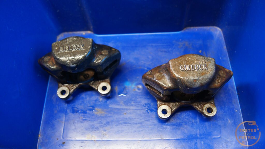
The rear axle is a local content item (along with all the braking system which is a "Girlock" copy of the Uk Girling gear), a Bog Warner type 68 as also fitted to Fords, Toyotas and Mitsubishis built in Aus at the time. The hand brake system is bespoke to this setup.
So, I've been digging with the stripping wheel on the grinder. I poked this scab a while back...

And yesterday I went full bore at it.


The previous owner was definitely a sculptor. There are places where the bog is 1-2CM thick.

Its messy AF, so will leave the rest of the stripping until I can get the car outside and make the rest of the dust natures problem

The strange thing is, the bog doesn't need to be this thick. I got a profile gauge today and using the good LH side as a sample, I compared it to the stripped RH side. Its not perfect, but its a lot closer to useable than I expected. There is no way it needed that much bog.

Once I have the rest of the bog off I'm going to etch prime the panel (takes the shine away, which is making it hard to see the shape) and then try my hand at shaping it with a hammer and dolly. Not sure how much better I can make the swage line, as its almost gone in places, but we'll see. Worst case, I keep an eye out for a replacement panel cut.
And yesterday I went full bore at it.
The previous owner was definitely a sculptor. There are places where the bog is 1-2CM thick.
Its messy AF, so will leave the rest of the stripping until I can get the car outside and make the rest of the dust natures problem
The strange thing is, the bog doesn't need to be this thick. I got a profile gauge today and using the good LH side as a sample, I compared it to the stripped RH side. Its not perfect, but its a lot closer to useable than I expected. There is no way it needed that much bog.
Once I have the rest of the bog off I'm going to etch prime the panel (takes the shine away, which is making it hard to see the shape) and then try my hand at shaping it with a hammer and dolly. Not sure how much better I can make the swage line, as its almost gone in places, but we'll see. Worst case, I keep an eye out for a replacement panel cut.
Finally, it's been a long time in the making, but for the first time in many years the Marina has brakes.
In the previous post, I refurbed and reassembled the rear brakes, but in the meantime I had also been working on the rest of the system. Unfortunately, things like this take time and money, both of which are a sticking point for me at the moment (mainly time, I'm waiting over a month for parts from the UK).
Even further back I started to strip the front calipers, which after some creative work with my compressor, I managed to do. First, I reinstalled the old pads, with a pry bar between them and used that to restrict the movement of the pistons, whilst pressurising the caliper and tapping the caliper body with a hammer. Eventually the pistons moved a little, but what made the biggest movement was using a punch and hammer to drive the piston out of the bore. Obviously, this is super destructive, so don't do this to pistons you want to keep (but pistons you want to keep shouldn't be stuck like these)

Out came one piston, along with a lot of sludge

This allowed me to slip the old piston back in after greasing it up, and using it to block the bore, and drive just the other piston out. I tried clamps, but there wasn't enough space with what I had, so ended up using a hose clamp to keep the piston from moving.

It worked a treat, and I ended up getting all four pistons out of the calipers in this way.
Now, before I go further, heed my warnings. Playing with hydraulics, compressed air, and brake fluid, is a dangerous game. Make sure you wear all your PPE. If it's not the crushing force of a piston flying out, it could be pressured brake fluid spraying into your face.
I should know, at one point when forcing 100+psi into the caliper I ended up with a fine mist of brake fluid spraying into my face. Thankfully I had safety glasses on, which stopped me from taking an eyeful of brake fluid and being blind, but it still wasn't pleasant. I have now upgraded to a full face shield for work like this.
As well as spraying my face, I didn't realise the fluid had travelled a meter or so behind me and ended up on the front of the Honda. Unfortunately, this sat on the paint and headlight overnight. The paint seems to have survived with only some minor marking, but the headlight has stained badly and will need replacing.

So yes, take care of yourself and your surroundings. ALWAYS wear the correct PPE. Also remember that plain old water neutralises brake fluid, so that should be the go-to for cleaning it off. Hydraulics are dangerous, if you aren't confident in what you are doing, seek professional support for the job.
Anyway, moving on, this is why the pistons were stuck. Deep corrosion.

After scrubbing the calipers in the parts washer, they spent a couple of days in the Evaporust bath to remove the rust.


They aren't perfect, and I probably should have painted them, but at the end of the day they are clean, internally rust-free and won't be seen behind the wheels.

I purchased a seal kit to suit the Girling Type 14 calipers as used on the Spitfire, PN GRK5005, which worked a treat. These Girlock calipers are almost an exact copy of the Girlings.
In went the piston seals, with lots of rubber grease. Make sure these sit flat, and arent twisted or pinched.

Next it's piston time. The pistons I used are once again from a Girling Type 14, PN 516212. These are slightly different where the dust boot sits. The Girlock pistons don't have a retaining groove, just a lip. The Girlings have a recessed groove. I figure since the seals I'm using are for the Girling, the Girlings pistons will be just fine (and to note, the old Girlock seals are visually the same). The overall dimensions of the piston are the same. Girling on the left, Girlock on the right.

The Girling piston had a much bigger lead in chamfer, which helps during assembly.

Pressing the pistons in was easy enough by hand. Lots of rubber grease, place it square and press it in with fingertips. Once it seats a bit, I used a long spanner over the face of the piston to push down evenly with both hands (one hand on each side of the caliper). It should go in with minimal force.

The dust boot is a prick. The inner lip sits in the piston recess, the outer lip just rests on the lip around the piston bore. A retaining ring holds it in place by friction. Getting this ring in place, without it pulling the boot off, took a few tries.

I found the easiest way to do it was to line the ends of the ring up so they are touching (spreading the ring open), and working from the back (opposite the open end of the ring) work it around the boot, holding it in place whilst you stretch the open ends of the ring into place. It's hard to describe, and do, but will make sense after a few tries.
Two calipers with new seals, pistons and boots.

I cleaned up the bleed nipples, making sure they were clear (they weren't), and refit the hard pipes. That's the calipers done.
Next in the firing line was the front rotors. I measured them a while ago and they came out as more or less new thickness, and have no lips. I feel like they were replaced not long before the car was laid up. Because of this, I don't want to replace them, that would be a damn waste. I was going to just send it, and use the pads to scrape the rust off them when it drives, but thought better of that when I had a good look. Crusty.
The best thing in this case was to remove the hub and rotor, and send the rotors off to be skimmed.
Before removing the hubs, I measured the runout in them. There should be 0.0245 - 0.1270mm play. This is to allow the bearings to expand when they warm up in use. Too tight and they will bind and fail. Too loose and they will wobble about and fail.
Well, the Lh side had this much play

0.185mm play. Quite a bit above the maximum allowable. I'm getting an awful lot of use out of my dial indicator with these old cars!
The RH side had zero play, not a thing. So both sides were set wrong. Glad I looked.
The LH side split pin was.... split. It's missing a whole leg, and was only sitting in place. It also pays to loosen the rotor bolts whilst the hub is on the car, just in case you need to stop it spinning. The rattle gun did this with no effort.

With the hub nut removed, the whole lot comes off pretty easily. The stub axle looks in good shape if a bit dirty.

One hub with rotor.

As a matter of course I bought a wheel bearing kit, as the old grease looked horrible, and there were signs of wear on the outer bearing races. The outer bearing was an LM11949 and the inner was L44649.
The back of the rotor looks worse than the front

Unlike the TVR, the rotors on the Marina came off easily with only minimal tapping with a hammer. I drove the old outer races out with a hammer and punch and gave the hub a good clean in the parts washer.

The rotors were sent away to be machined and came back looking good. They could've skimmed a little more off, but I'm sure the pads will scrub them clean in no time.

Before the rotor goes back on, the new bearings were pressed into the hub. The new bearings.

The new race was pressed in with the old race, and a deep socket


The rotor was loosely attached. Note the markings on the hub reminding me the rotor bolts aren't torqued. This can only be done on the car, using a long pry bar to lock the hub from spinning.

The bearings were packed and fitted, along with a new seal.

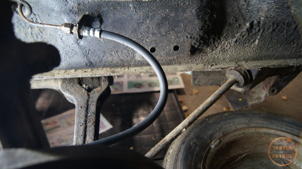
Before fitting the hub, I quickly swapped the old blocked front hoses for the new ones. These are Land Rover hoses, PN BR0764
And on goes the hub.

Set to the correct runout

With the caps and calipers fitted

Both hubs had the rotor bolts torqued down, so the markings were removed

The last few pieces of the puzzle were the master cylinder (which I sent off to be resleeved and rekitted), a new brake pipe from the master cylinder (since I damaged the old one removing it. A friend helped make a new one), and new pad fitting kit (in transit from the UK).
The brake master and clutch slave I sent away to be resleeved came back looking lovely. Nice new stainless bores, as well as a good cleanup. Won't have to worry about these rusting up again.

Of course, I couldn't just fit the nice clean cylinder to the rubbish looking firewall plate, so that got a wire brush and a coat of paint.

It's hard to believe it's the same master cylinder, and the same cap. I cleaned and used Araldite to fix the crack in the cap.

The pedals got new clevis pins, since the old ones had seen their share of work!

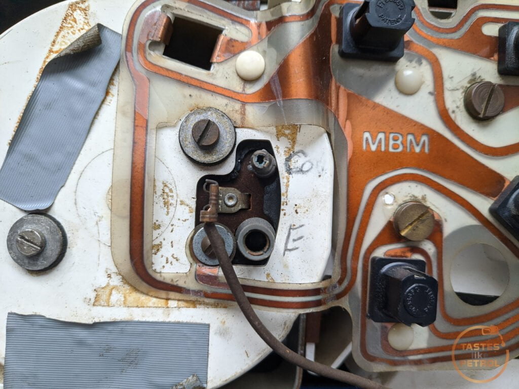
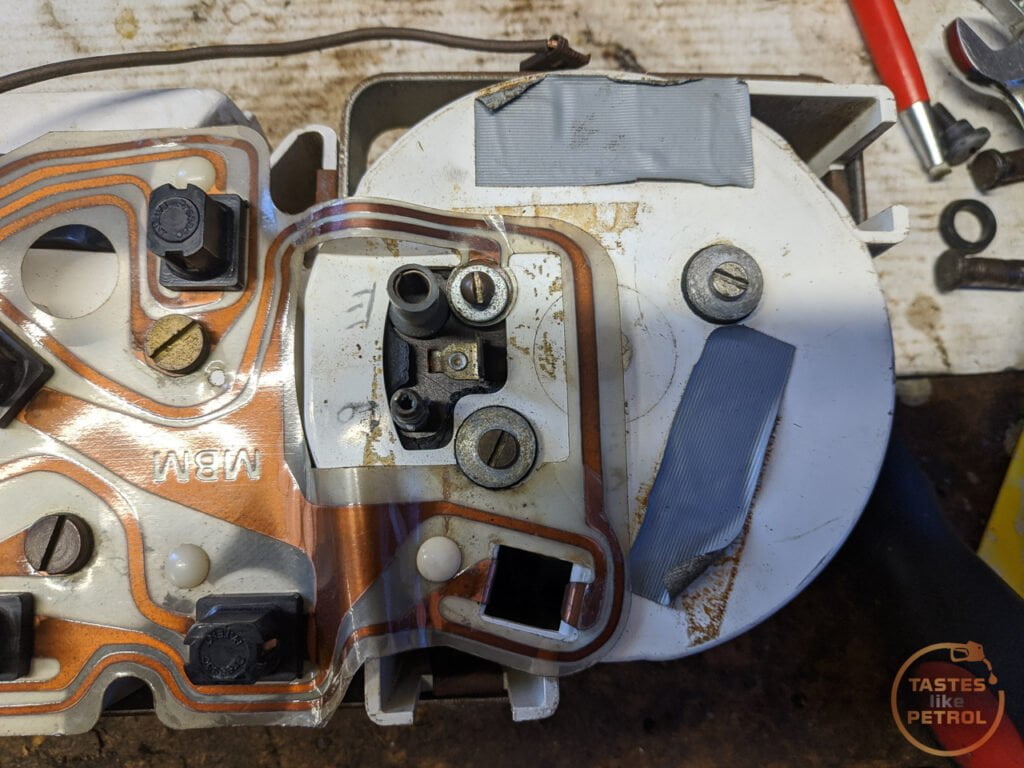
And finally, the brake light switch was tested


Which revealed that it didn't work. The switch is easy enough to strip, these tabs on the side need to be pressed to remove the bottom of the unit and pull the guts out

How this switch works confused me for a bit. When you remove the top from the bottom, it actually moves where the internal contact is, and if you don't spot it during disassembly it can be confusing. It got to the point I purchased a cheap replacement so I could work out how it's assembled.
This is whats inside the switch, and how it came apart

As it turns out, as seen on this replacement switch, the U shaped contact goes under the two legs.

It's a Normally Closed switch, so it makes a circuit when the switch is released. When the brake pedal is pressed it's releasing the switch, which makes the circuit, otherwise normally it's pressed in, which moves the U shaped contact away from the two legs. The spring sits under the U shaped contact which pushes it up.
The replacement switch was a bit cheap, so instead I cleaned up the contacts of the old one and reassembled it. It takes some fiddling to keep the contact under the two legs whilst you slip the base in to the top housing, but it can be done.
A test shows that when pressed, the circuit is broken

And released, it makes the circuit

The original Lucas Australia switch lives to fight another day.
The pad fitting kit finally arrived today, so I fitted the NOS pads, new shims and new pins. It's a bit of a pain with new pads and new thickness rotors, its all very tight, but it's there.

I then drew fluid through with a vacuum bleeder, until all three bleed nipples had clean fluid coming through. Then it was back to the old one-man bleeder to finish the job. The brake pedal is now firm, with good travel. The rear adjusters have adjusted up (can hear the shoes slightly dragging the drum), and the hand brake is working. Everything needs a good bedding in, but for now, everything is doing what it should, and there seems to be no leaks. I don't know when it last had brakes, but it may not have been in this millennium.
Now all I'm waiting on is a clutch master cylinder, which is en route from the UK, and a drive shaft that will be on its way to me tomorrow from down south. Once they arrive, we should be good for a trip up the driveway. Excite.
In the previous post, I refurbed and reassembled the rear brakes, but in the meantime I had also been working on the rest of the system. Unfortunately, things like this take time and money, both of which are a sticking point for me at the moment (mainly time, I'm waiting over a month for parts from the UK).
Even further back I started to strip the front calipers, which after some creative work with my compressor, I managed to do. First, I reinstalled the old pads, with a pry bar between them and used that to restrict the movement of the pistons, whilst pressurising the caliper and tapping the caliper body with a hammer. Eventually the pistons moved a little, but what made the biggest movement was using a punch and hammer to drive the piston out of the bore. Obviously, this is super destructive, so don't do this to pistons you want to keep (but pistons you want to keep shouldn't be stuck like these)
Out came one piston, along with a lot of sludge
This allowed me to slip the old piston back in after greasing it up, and using it to block the bore, and drive just the other piston out. I tried clamps, but there wasn't enough space with what I had, so ended up using a hose clamp to keep the piston from moving.
It worked a treat, and I ended up getting all four pistons out of the calipers in this way.
Now, before I go further, heed my warnings. Playing with hydraulics, compressed air, and brake fluid, is a dangerous game. Make sure you wear all your PPE. If it's not the crushing force of a piston flying out, it could be pressured brake fluid spraying into your face.
I should know, at one point when forcing 100+psi into the caliper I ended up with a fine mist of brake fluid spraying into my face. Thankfully I had safety glasses on, which stopped me from taking an eyeful of brake fluid and being blind, but it still wasn't pleasant. I have now upgraded to a full face shield for work like this.
As well as spraying my face, I didn't realise the fluid had travelled a meter or so behind me and ended up on the front of the Honda. Unfortunately, this sat on the paint and headlight overnight. The paint seems to have survived with only some minor marking, but the headlight has stained badly and will need replacing.
So yes, take care of yourself and your surroundings. ALWAYS wear the correct PPE. Also remember that plain old water neutralises brake fluid, so that should be the go-to for cleaning it off. Hydraulics are dangerous, if you aren't confident in what you are doing, seek professional support for the job.
Anyway, moving on, this is why the pistons were stuck. Deep corrosion.
After scrubbing the calipers in the parts washer, they spent a couple of days in the Evaporust bath to remove the rust.
They aren't perfect, and I probably should have painted them, but at the end of the day they are clean, internally rust-free and won't be seen behind the wheels.
I purchased a seal kit to suit the Girling Type 14 calipers as used on the Spitfire, PN GRK5005, which worked a treat. These Girlock calipers are almost an exact copy of the Girlings.
In went the piston seals, with lots of rubber grease. Make sure these sit flat, and arent twisted or pinched.
Next it's piston time. The pistons I used are once again from a Girling Type 14, PN 516212. These are slightly different where the dust boot sits. The Girlock pistons don't have a retaining groove, just a lip. The Girlings have a recessed groove. I figure since the seals I'm using are for the Girling, the Girlings pistons will be just fine (and to note, the old Girlock seals are visually the same). The overall dimensions of the piston are the same. Girling on the left, Girlock on the right.
The Girling piston had a much bigger lead in chamfer, which helps during assembly.
Pressing the pistons in was easy enough by hand. Lots of rubber grease, place it square and press it in with fingertips. Once it seats a bit, I used a long spanner over the face of the piston to push down evenly with both hands (one hand on each side of the caliper). It should go in with minimal force.
The dust boot is a prick. The inner lip sits in the piston recess, the outer lip just rests on the lip around the piston bore. A retaining ring holds it in place by friction. Getting this ring in place, without it pulling the boot off, took a few tries.
I found the easiest way to do it was to line the ends of the ring up so they are touching (spreading the ring open), and working from the back (opposite the open end of the ring) work it around the boot, holding it in place whilst you stretch the open ends of the ring into place. It's hard to describe, and do, but will make sense after a few tries.
Two calipers with new seals, pistons and boots.
I cleaned up the bleed nipples, making sure they were clear (they weren't), and refit the hard pipes. That's the calipers done.
Next in the firing line was the front rotors. I measured them a while ago and they came out as more or less new thickness, and have no lips. I feel like they were replaced not long before the car was laid up. Because of this, I don't want to replace them, that would be a damn waste. I was going to just send it, and use the pads to scrape the rust off them when it drives, but thought better of that when I had a good look. Crusty.
The best thing in this case was to remove the hub and rotor, and send the rotors off to be skimmed.
Before removing the hubs, I measured the runout in them. There should be 0.0245 - 0.1270mm play. This is to allow the bearings to expand when they warm up in use. Too tight and they will bind and fail. Too loose and they will wobble about and fail.
Well, the Lh side had this much play
0.185mm play. Quite a bit above the maximum allowable. I'm getting an awful lot of use out of my dial indicator with these old cars!
The RH side had zero play, not a thing. So both sides were set wrong. Glad I looked.
The LH side split pin was.... split. It's missing a whole leg, and was only sitting in place. It also pays to loosen the rotor bolts whilst the hub is on the car, just in case you need to stop it spinning. The rattle gun did this with no effort.
With the hub nut removed, the whole lot comes off pretty easily. The stub axle looks in good shape if a bit dirty.
One hub with rotor.
As a matter of course I bought a wheel bearing kit, as the old grease looked horrible, and there were signs of wear on the outer bearing races. The outer bearing was an LM11949 and the inner was L44649.
The back of the rotor looks worse than the front
Unlike the TVR, the rotors on the Marina came off easily with only minimal tapping with a hammer. I drove the old outer races out with a hammer and punch and gave the hub a good clean in the parts washer.
The rotors were sent away to be machined and came back looking good. They could've skimmed a little more off, but I'm sure the pads will scrub them clean in no time.
Before the rotor goes back on, the new bearings were pressed into the hub. The new bearings.
The new race was pressed in with the old race, and a deep socket
The rotor was loosely attached. Note the markings on the hub reminding me the rotor bolts aren't torqued. This can only be done on the car, using a long pry bar to lock the hub from spinning.
The bearings were packed and fitted, along with a new seal.
Before fitting the hub, I quickly swapped the old blocked front hoses for the new ones. These are Land Rover hoses, PN BR0764
And on goes the hub.
Set to the correct runout
With the caps and calipers fitted
Both hubs had the rotor bolts torqued down, so the markings were removed
The last few pieces of the puzzle were the master cylinder (which I sent off to be resleeved and rekitted), a new brake pipe from the master cylinder (since I damaged the old one removing it. A friend helped make a new one), and new pad fitting kit (in transit from the UK).
The brake master and clutch slave I sent away to be resleeved came back looking lovely. Nice new stainless bores, as well as a good cleanup. Won't have to worry about these rusting up again.
Of course, I couldn't just fit the nice clean cylinder to the rubbish looking firewall plate, so that got a wire brush and a coat of paint.
It's hard to believe it's the same master cylinder, and the same cap. I cleaned and used Araldite to fix the crack in the cap.
The pedals got new clevis pins, since the old ones had seen their share of work!
And finally, the brake light switch was tested
Which revealed that it didn't work. The switch is easy enough to strip, these tabs on the side need to be pressed to remove the bottom of the unit and pull the guts out
How this switch works confused me for a bit. When you remove the top from the bottom, it actually moves where the internal contact is, and if you don't spot it during disassembly it can be confusing. It got to the point I purchased a cheap replacement so I could work out how it's assembled.
This is whats inside the switch, and how it came apart
As it turns out, as seen on this replacement switch, the U shaped contact goes under the two legs.
It's a Normally Closed switch, so it makes a circuit when the switch is released. When the brake pedal is pressed it's releasing the switch, which makes the circuit, otherwise normally it's pressed in, which moves the U shaped contact away from the two legs. The spring sits under the U shaped contact which pushes it up.
The replacement switch was a bit cheap, so instead I cleaned up the contacts of the old one and reassembled it. It takes some fiddling to keep the contact under the two legs whilst you slip the base in to the top housing, but it can be done.
A test shows that when pressed, the circuit is broken
And released, it makes the circuit
The original Lucas Australia switch lives to fight another day.
The pad fitting kit finally arrived today, so I fitted the NOS pads, new shims and new pins. It's a bit of a pain with new pads and new thickness rotors, its all very tight, but it's there.
I then drew fluid through with a vacuum bleeder, until all three bleed nipples had clean fluid coming through. Then it was back to the old one-man bleeder to finish the job. The brake pedal is now firm, with good travel. The rear adjusters have adjusted up (can hear the shoes slightly dragging the drum), and the hand brake is working. Everything needs a good bedding in, but for now, everything is doing what it should, and there seems to be no leaks. I don't know when it last had brakes, but it may not have been in this millennium.
Now all I'm waiting on is a clutch master cylinder, which is en route from the UK, and a drive shaft that will be on its way to me tomorrow from down south. Once they arrive, we should be good for a trip up the driveway. Excite.
Bingo. Girling Lockheed. AUS made to meet the "local content" requirements. So far all Girlock stuff has been direct ripoffs of Girling (except the clutch slave, which Girlock altered the design for the better, but still used a Girling seal kit).
I would've painted the calipers if they were going to be seen, but I'm currently doing this work on almost no budget (no job, no income for hobbies) and it was either use an old can of red paint, or don't paint. I chose not to paint them, and you won't see them behind the steelies.
I would've painted the calipers if they were going to be seen, but I'm currently doing this work on almost no budget (no job, no income for hobbies) and it was either use an old can of red paint, or don't paint. I chose not to paint them, and you won't see them behind the steelies.
It feels like it's been a huge uphill battle getting a working tacho in this car, but I think I have finally mastered it.
Over the past few months, I have somehow ended up with a few different clusters, including two with the elusive tachometer module, and the one with the non-functioning clock I previously made a post about.
The first three dial with tacho I bought from Trademe.
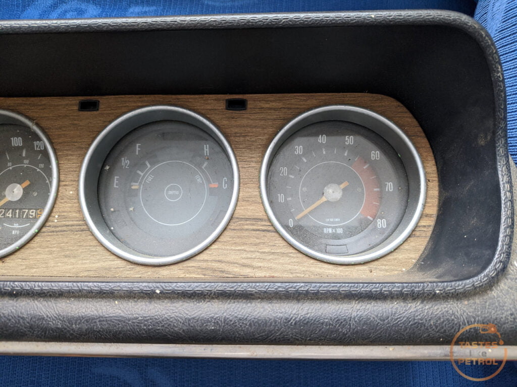
It was the correct Aus cluster, with the lower 5500RPM redline, and a couple of other small differences as I would later find out.
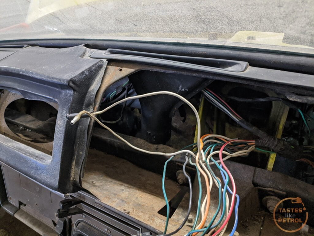
Eager to get the tacho in and working I started to dig around the wiring diagrams to work out what I needed to do. I had heard rumours that the wiring was already in the dash, behind the cluster, and sure enough, after some poking around, I noticed a white wire tucked away with a joiner in the middle of it. This tracked with what I was expecting to find based on the wiring diagrams.
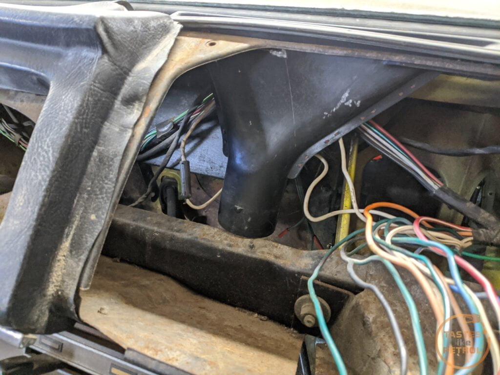
It was a big loop in the harness. I fished it out from behind the duct and unplugged it. A couple of quick checks and I was sure it was the coil trigger for the tacho. On the cars without tachos, this is just looped in the dash but needs to be connected or it cuts power to the coil. I guess it made it cheaper and easier, to just use the one harness.
The back of the tacho unit has corresponding bullet terminals
So I plugged it into the dash, and bam, nothing happened. Well, the alt/oil lights worked as they should, but the tacho was dead. I was a bit miffed
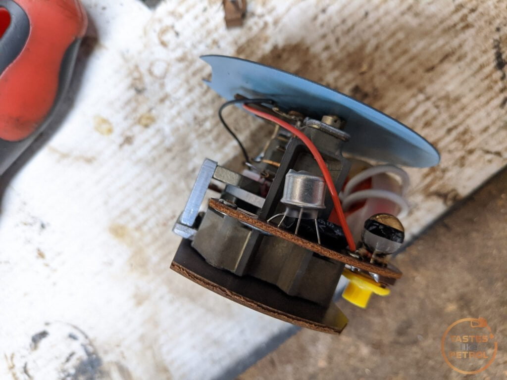
Nothing more to do then but to get to disassembly and find out what's wrong. The tacho unit is held into its housing by a couple of screws through the back, and the fascia/glass in the front.
This is what the module looks like removed.

Having already googled "why does my Smiths RVI tacho not work" I could already see something was wrong.
Those four holes in the foreground, under that red wire? Yeah, according to google there should be a transistor there, and it's crucial to the operation of the unit.
The solder pads had clearly been messed with too. It looked like someone had desoldered the component with a blowtorch.
I hit the seller up and asked if he knew why it's been molested, and he just pleaded ignorance and fobbed me off with a "oh well, it's an old part".
I suspect the capacitor or transistor had failed at some point (which is common) and someone tried to fix it. Failing to have the right parts on hand or something, they just chucked it back together and set it aside.
As fate would have it, a fellow classic car sufferer on a forum I'm on knew I'm suffering the Marina affliction and mentioned that he had come across some Marina bits as part of a garage clearout, and would I be interested in a cluster he found? Heck yeah I would! The legend donated this to the cause, so a huge Thank You.
So, this was the second tacho cluster I have. It came in a tidy surround, but it was brown, not black. No issue, They are easy to swap, and I only really needed the guts.

Differences to observe. The silver rings around the dials, instead of the black the Aus cars have, the 6000RPM redline on the tacho face (ignore the askew tacho, I had already started to disassemble it), and the different markings on the fuel and temp scales (0 instead of E, and adding the N to temp). One final difference I didn't notice initially, is the warning lights are different, with some either doing different functions, or in the case of the indicator telltale lamps, not there at all. The UK cars seem to use one single green light to show the indicator is on, whilst the Aus cars use the two spaces above the center dial as left and right signals.

But it barely exceeded 1000rpm when revving the engine. I think this one may have been suffering from the known issues Smiths RVI tachos suffer from (bad capacitors), but instead of messing around with the old inductive RVI style guts, I spent a hefty whack of cash on the Spiyda RVI-RVC conversion board.
The original RVI tacho is current sensing, so it intercepts the power feed to the ignition coil, and by some wizardry senses the pulses and creates a signal for the tacho to output. The issue with this is apparently the tacho only works with points, and in the future I want the option of upgrading to electronic ignition without having to replace the tacho again, so it had to go.
The Spiyda board removes all the existing guts from the tacho, and replaces it with a new board that reads the signal from the negative terminal on the coil (like 90% of tachometers). Heck, it can even be fed a signal from an ECU. It's pretty swish stuff.
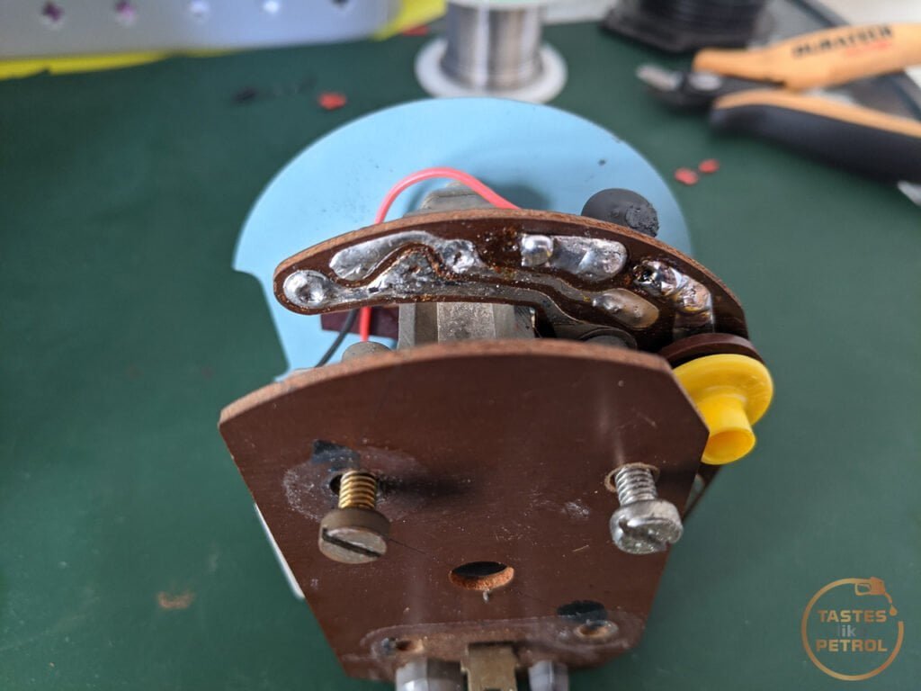
I stripped the second tacho out of the housing, and you can see the missing component of tacho one here; the silver can is a special transistor.
I started with the guts of the first tacho since that one was dead in the water anyway. Spiyda has extensive instructions on its site, here, so follow those, but this is how I went about it.
The first step is to remove the needle. You don't need to mark where the needle sits, just make sure the mechanism is against its stop when you refit the needle. To remove it I used an old business card with a notch cut in it, and a sturdy fork. The business card is to reduce the risk of damage to the face.
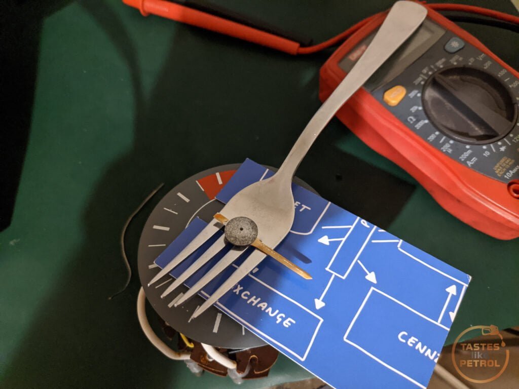
A swift lever upwards popped the needle off.

Two little screws secure the face. The kit comes with a tiny screwdriver to remove these.
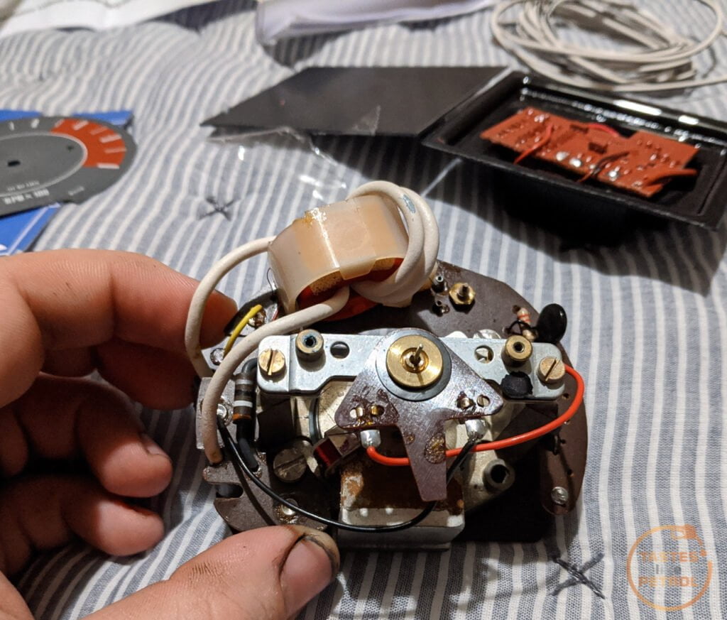
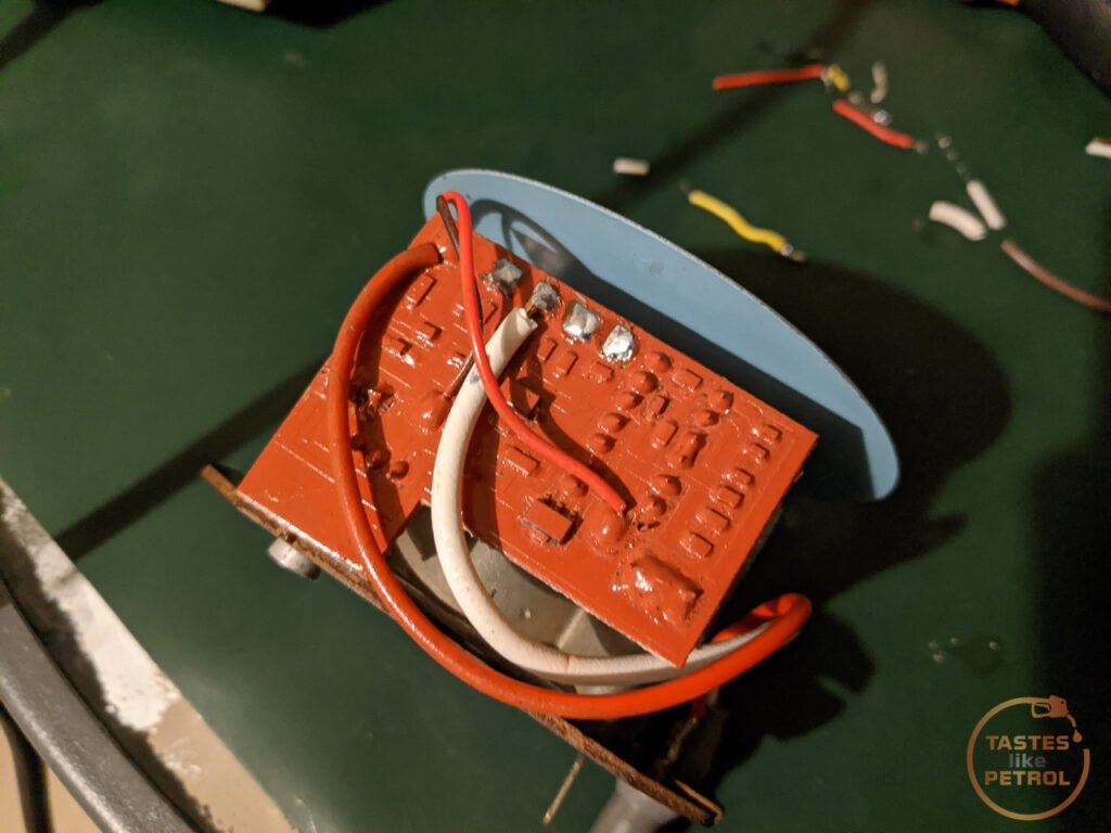
Now cut the power feed wire, and the two thin wires to the mechanism and remove the two screws holding the circuit to the frame. It should pull off the front.

The new board then gets screwed in place

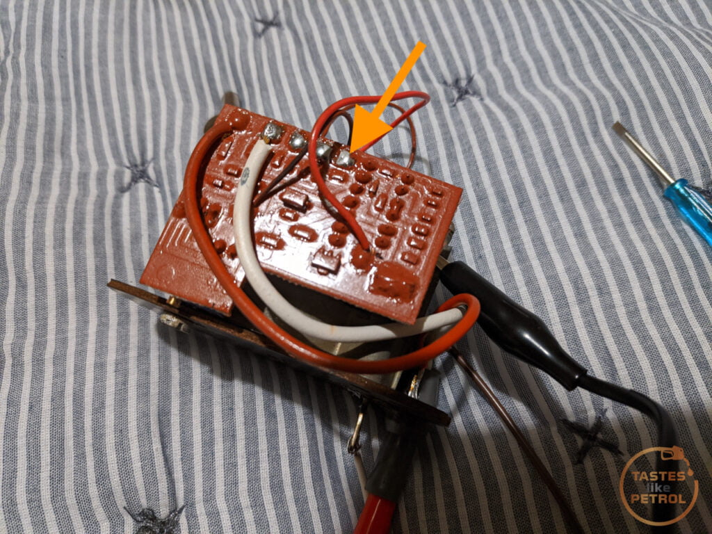
Now solder the wires in their respective places (in my case the black and red wires had to be swapped). and you're ready for testing and calibrating.

Now, I did make a mistake in the above photo. It turns out that the video I was following, made by Spiyda, was out of date, so you no longer calibrate the unit by putting the red clip onto the tacho feed (which I made from the old RVI tacho feed, by cutting a section off and soldering it to the board). Instead, you need to clip the red clip to the solder pad on the far right, closest to the big chip (on the other side of the board), or solder pad number 4.
With 12v connected to the spade terminal on the back, the red clip on the solder pad and the black clip on the metal frame, it's time to calibrate.
Now, this was a real ballache for me. In the end, I don't know why it suddenly started to work properly, or what I did differently, but it was chaos.
The instruction and files to download for calibration are on the Spiyda site, here.
Basically, you play a square wave audio file at a certain frequency through the cable at full volume. That frequency should correspond with a certain RPM reading on the tacho. Since I was using a low revving 4 cylinder engine, I used the 100 and 200hz files as this should read 3000rpm and 6000rpm on the tacho.
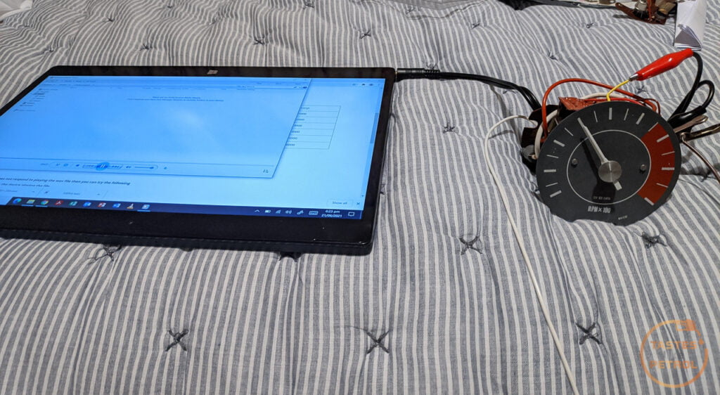
I had various levels of success depending on what device I was using. My Macbook, no good. My phone, initially average. My windows based Dell tablet, good but with some issues.
I could get it to read 3000rpm, but doubling the frequency would either make the needle drop or only increase by a small amount. There was also a big jump in the needle at the start and it kinda crept down. This Gif shows the issue I was having. This is the 100-200 sweep, where it starts at 100hz and then shifts to 200hz. You can see the 100hz once the needle settles down, but then when it changes to 200hz the needle drops to just under 2500RPM.
I had been in contact with Spiyda support for a while, since even before calibration issues I had issues getting the unit to respond in the first place, and they had been very helpful in getting to where I was, with prompt replies, but then the support suddenly went cold and I heard nothing further from them.
It even got to the point of stripping down the second tacho and seeing if the issues were limited to the first one; they weren't.

I persisted with various things, and eventually I had great success using my phone. I don't know what changed, or why it worked now but didn't earlier, but suddenly I had 3000RPM at 100hz and 6000RPM at 200hz. It needed a small tweak of the calibration pot on the back, but it was rock solid.
With much excitement, I rushed to the garage and reassembled it into its housing.

And with a temporary wire run outside the car from the coil negative to the cluster, I fired the engine up. Nothing. *Sigh*
And then I remembered there were options for the input. There was a high voltage and low voltage signal option. In hindsight, if I had paid attention initially I wouldn't have wired the input to the high voltage "sports coil" option, and should've used the "normal coil" option. Oops.

It was easy to fix once I removed the guts from the cluster and moved the white wire one pad to the right.
I reassembled the cluster and plugged it in.
https://youtu.be/YC74v52vYlk
Success! I've run the car a couple of times since, and the tacho seems to be fairly accurate. It doesn't need to be 100% accurate, just within the ballpark is good enough, and better than Leyland would've done. It responds quickly and is very stable.

I still need to run the tacho wire inside the car, but that's easy enough to do. I should probably fit the surround back on the gauges too since they are more or less done now.
Over the past few months, I have somehow ended up with a few different clusters, including two with the elusive tachometer module, and the one with the non-functioning clock I previously made a post about.
The first three dial with tacho I bought from Trademe.
It was the correct Aus cluster, with the lower 5500RPM redline, and a couple of other small differences as I would later find out.
Eager to get the tacho in and working I started to dig around the wiring diagrams to work out what I needed to do. I had heard rumours that the wiring was already in the dash, behind the cluster, and sure enough, after some poking around, I noticed a white wire tucked away with a joiner in the middle of it. This tracked with what I was expecting to find based on the wiring diagrams.
It was a big loop in the harness. I fished it out from behind the duct and unplugged it. A couple of quick checks and I was sure it was the coil trigger for the tacho. On the cars without tachos, this is just looped in the dash but needs to be connected or it cuts power to the coil. I guess it made it cheaper and easier, to just use the one harness.
The back of the tacho unit has corresponding bullet terminals
So I plugged it into the dash, and bam, nothing happened. Well, the alt/oil lights worked as they should, but the tacho was dead. I was a bit miffed
Nothing more to do then but to get to disassembly and find out what's wrong. The tacho unit is held into its housing by a couple of screws through the back, and the fascia/glass in the front.
This is what the module looks like removed.
Having already googled "why does my Smiths RVI tacho not work" I could already see something was wrong.
Those four holes in the foreground, under that red wire? Yeah, according to google there should be a transistor there, and it's crucial to the operation of the unit.
The solder pads had clearly been messed with too. It looked like someone had desoldered the component with a blowtorch.
I hit the seller up and asked if he knew why it's been molested, and he just pleaded ignorance and fobbed me off with a "oh well, it's an old part".
I suspect the capacitor or transistor had failed at some point (which is common) and someone tried to fix it. Failing to have the right parts on hand or something, they just chucked it back together and set it aside.
As fate would have it, a fellow classic car sufferer on a forum I'm on knew I'm suffering the Marina affliction and mentioned that he had come across some Marina bits as part of a garage clearout, and would I be interested in a cluster he found? Heck yeah I would! The legend donated this to the cause, so a huge Thank You.
So, this was the second tacho cluster I have. It came in a tidy surround, but it was brown, not black. No issue, They are easy to swap, and I only really needed the guts.
Differences to observe. The silver rings around the dials, instead of the black the Aus cars have, the 6000RPM redline on the tacho face (ignore the askew tacho, I had already started to disassemble it), and the different markings on the fuel and temp scales (0 instead of E, and adding the N to temp). One final difference I didn't notice initially, is the warning lights are different, with some either doing different functions, or in the case of the indicator telltale lamps, not there at all. The UK cars seem to use one single green light to show the indicator is on, whilst the Aus cars use the two spaces above the center dial as left and right signals.
- removes anorak* Right, so this cluster. Excitedly I plugged it into the car, and we had some success. The tacho moved!
But it barely exceeded 1000rpm when revving the engine. I think this one may have been suffering from the known issues Smiths RVI tachos suffer from (bad capacitors), but instead of messing around with the old inductive RVI style guts, I spent a hefty whack of cash on the Spiyda RVI-RVC conversion board.
The original RVI tacho is current sensing, so it intercepts the power feed to the ignition coil, and by some wizardry senses the pulses and creates a signal for the tacho to output. The issue with this is apparently the tacho only works with points, and in the future I want the option of upgrading to electronic ignition without having to replace the tacho again, so it had to go.
The Spiyda board removes all the existing guts from the tacho, and replaces it with a new board that reads the signal from the negative terminal on the coil (like 90% of tachometers). Heck, it can even be fed a signal from an ECU. It's pretty swish stuff.
I stripped the second tacho out of the housing, and you can see the missing component of tacho one here; the silver can is a special transistor.
I started with the guts of the first tacho since that one was dead in the water anyway. Spiyda has extensive instructions on its site, here, so follow those, but this is how I went about it.
The first step is to remove the needle. You don't need to mark where the needle sits, just make sure the mechanism is against its stop when you refit the needle. To remove it I used an old business card with a notch cut in it, and a sturdy fork. The business card is to reduce the risk of damage to the face.
A swift lever upwards popped the needle off.
Two little screws secure the face. The kit comes with a tiny screwdriver to remove these.
Now cut the power feed wire, and the two thin wires to the mechanism and remove the two screws holding the circuit to the frame. It should pull off the front.
The new board then gets screwed in place
Now solder the wires in their respective places (in my case the black and red wires had to be swapped). and you're ready for testing and calibrating.
Now, I did make a mistake in the above photo. It turns out that the video I was following, made by Spiyda, was out of date, so you no longer calibrate the unit by putting the red clip onto the tacho feed (which I made from the old RVI tacho feed, by cutting a section off and soldering it to the board). Instead, you need to clip the red clip to the solder pad on the far right, closest to the big chip (on the other side of the board), or solder pad number 4.
With 12v connected to the spade terminal on the back, the red clip on the solder pad and the black clip on the metal frame, it's time to calibrate.
Now, this was a real ballache for me. In the end, I don't know why it suddenly started to work properly, or what I did differently, but it was chaos.
The instruction and files to download for calibration are on the Spiyda site, here.
Basically, you play a square wave audio file at a certain frequency through the cable at full volume. That frequency should correspond with a certain RPM reading on the tacho. Since I was using a low revving 4 cylinder engine, I used the 100 and 200hz files as this should read 3000rpm and 6000rpm on the tacho.
I had various levels of success depending on what device I was using. My Macbook, no good. My phone, initially average. My windows based Dell tablet, good but with some issues.
I could get it to read 3000rpm, but doubling the frequency would either make the needle drop or only increase by a small amount. There was also a big jump in the needle at the start and it kinda crept down. This Gif shows the issue I was having. This is the 100-200 sweep, where it starts at 100hz and then shifts to 200hz. You can see the 100hz once the needle settles down, but then when it changes to 200hz the needle drops to just under 2500RPM.
I had been in contact with Spiyda support for a while, since even before calibration issues I had issues getting the unit to respond in the first place, and they had been very helpful in getting to where I was, with prompt replies, but then the support suddenly went cold and I heard nothing further from them.
It even got to the point of stripping down the second tacho and seeing if the issues were limited to the first one; they weren't.
I persisted with various things, and eventually I had great success using my phone. I don't know what changed, or why it worked now but didn't earlier, but suddenly I had 3000RPM at 100hz and 6000RPM at 200hz. It needed a small tweak of the calibration pot on the back, but it was rock solid.
With much excitement, I rushed to the garage and reassembled it into its housing.
And with a temporary wire run outside the car from the coil negative to the cluster, I fired the engine up. Nothing. *Sigh*
And then I remembered there were options for the input. There was a high voltage and low voltage signal option. In hindsight, if I had paid attention initially I wouldn't have wired the input to the high voltage "sports coil" option, and should've used the "normal coil" option. Oops.
It was easy to fix once I removed the guts from the cluster and moved the white wire one pad to the right.
I reassembled the cluster and plugged it in.
https://youtu.be/YC74v52vYlk
Success! I've run the car a couple of times since, and the tacho seems to be fairly accurate. It doesn't need to be 100% accurate, just within the ballpark is good enough, and better than Leyland would've done. It responds quickly and is very stable.
I still need to run the tacho wire inside the car, but that's easy enough to do. I should probably fit the surround back on the gauges too since they are more or less done now.
It's been a while since I had done any work on the Marina. The Tacho kinda progressed in the background, but most of the focus had been on getting the Carib going.
But with the Carib on the road, I turned my attention to the Marina again.
One of the things that had to be done before I could attempt to move the car under its own power was to rebuild the driveshaft/propshaft.
I knew from when I first went under the car that the center hanger bearing was completely shot, and had collapsed, so at the very least that needed to be replaced.

Ages ago (about two months ago) I slid under the car and removed the driveshaft.

Hanger bearing was looking a bit sad
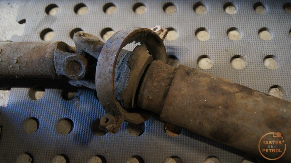
I'm glad I took it out and checked, it turns out the bolt that secures the two halves together was... missing.
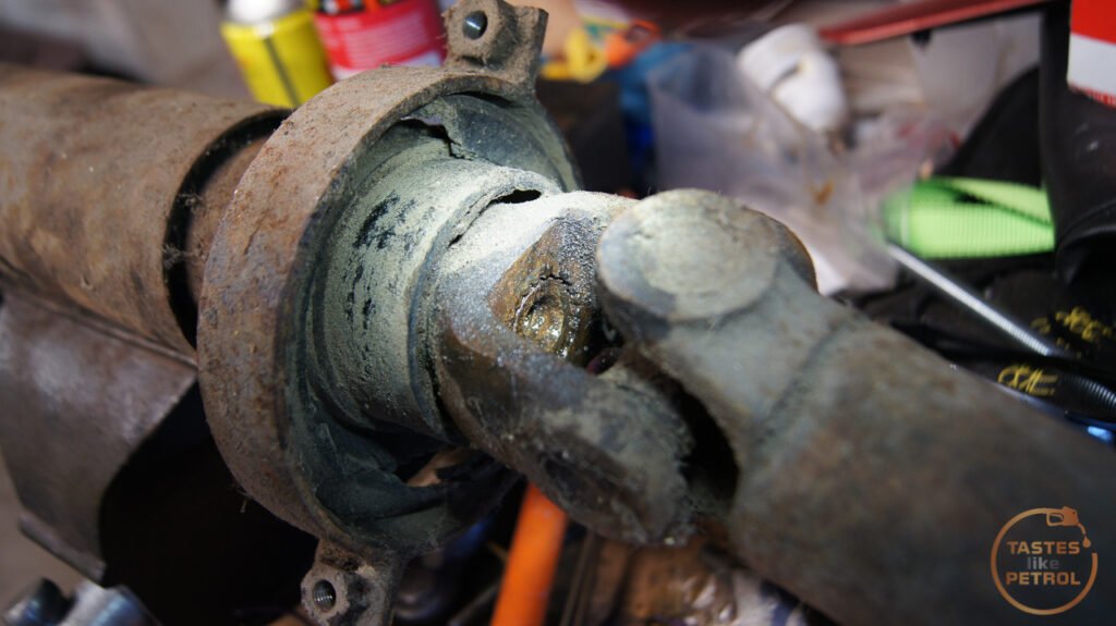
There was also play in at least one of the universal joints, and it wasn't the one secured by clips. Two of the three UJs are secured by a process called Staking, where they physically deform the metal around the edge of the cap to hold it in place. This is a real pain because it needs some skill and usually a bigger press than I have to replace them.

You can see better detail in this example image
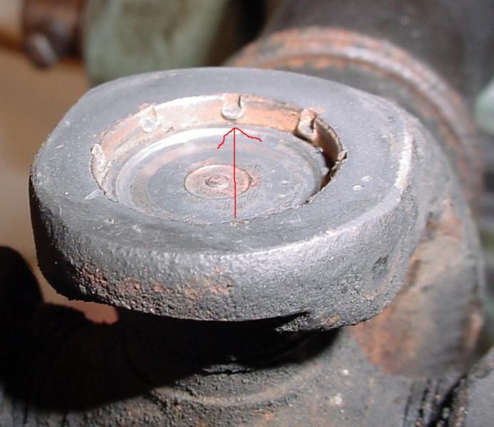
A normal universal joint is secured by a big circlip in a groove, which is far easier to work with.
This prompted me to reach out to a fellow Marina owner and purchase a spare driveshaft off him, which although had a failed center bearing too, used Circlip style UJs and had the securing bolt for the two halves.
I finally got around to attacking the replacement driveshaft the other day. I wanted to refurbish the whole thing since it was old and I didn't want to have to pull it out later to replace the UJs.
There is a great video by Chris Fix on how to replace UJs. He makes it look easy, but I hated this job.
https://youtu.be/5gOeBE-ylQw
First I cleaned it up a bit, marked the alignment and removed the clips with a pair of circlip pliers
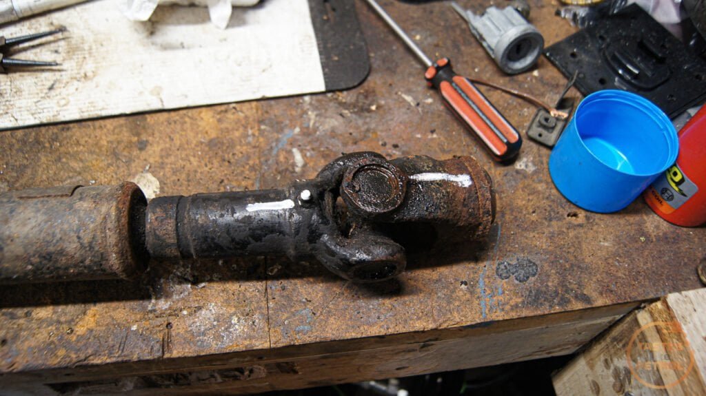
This end was pretty straightforward. Big socket (24mm impact) underneath, and a smaller one that fits into the recess (14mm impact, 16mm normal) on top and using a big hammer, smash the 14mm socket down, pushing the UJ cap out the bottom.
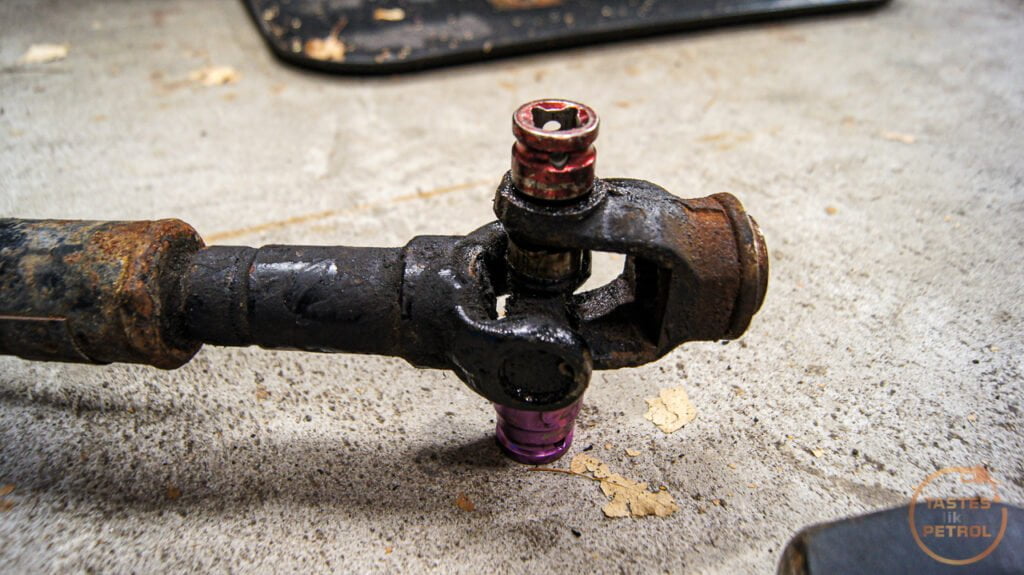
It came apart more or less with no trouble. Push the joint down, pull the cap out. push the joint back up, pull the cap out. Done.
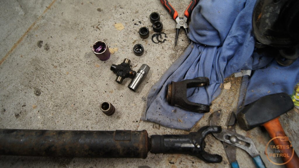
To fit the new joint, I found it best to lubricate the recess you are pressing the caps into with clean ATF, and then press them both in together using a bench vice. This helps to press them in square. I didn't do this for the first couple, I used the method of hammering the new caps into place.
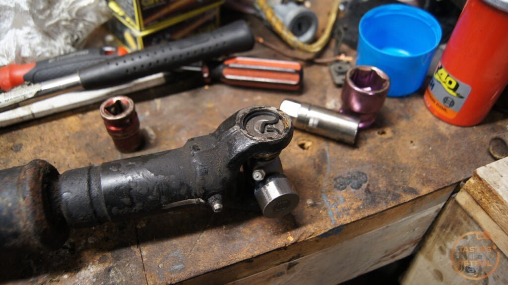
I did unfortunately find out why they recommend sealed joints without grease fittings... There is not enough room in the joint for the long grease fitting, and you would risk breaking the fitting off when the joint moves.
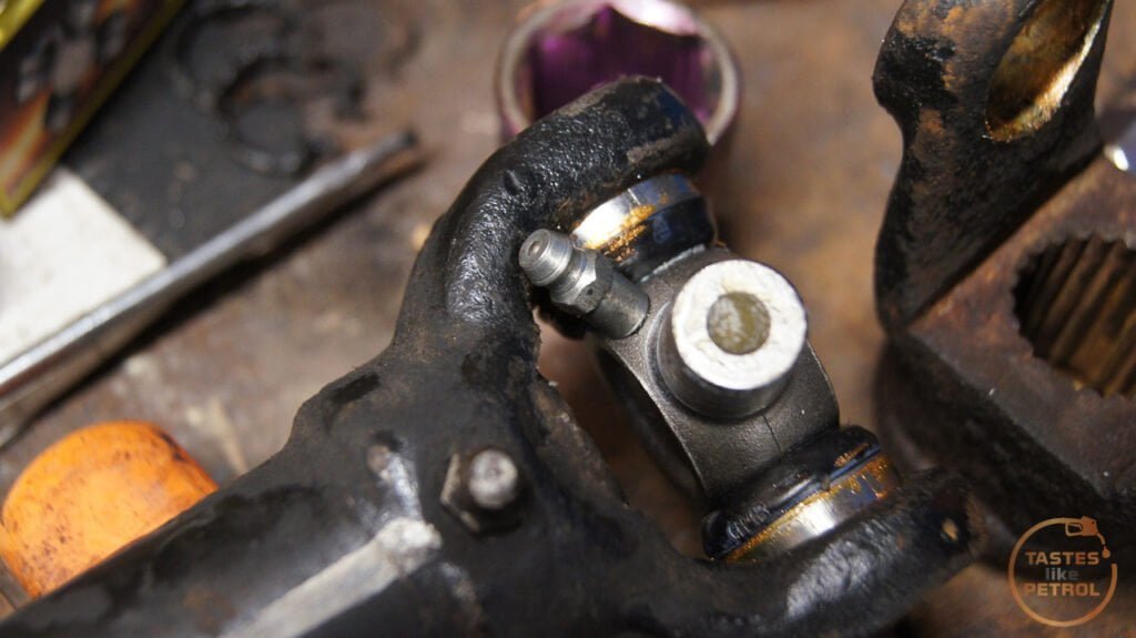
These joints were very cheap on clearance though, so I persisted anyway and dealt with that later.
One end of the driveshaft done. The new joint is smooth and feels great. A few pumps of the grease gun and it was ready for action. Kinda.

The next joint was well jammed in place, to the point it blew the end out of the cap before dislodging it
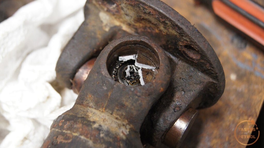
You can tell from the state of it when it did come out that had some issues. Being a sealed unit, you can't grease it, so once the grease hardened it was all bad.
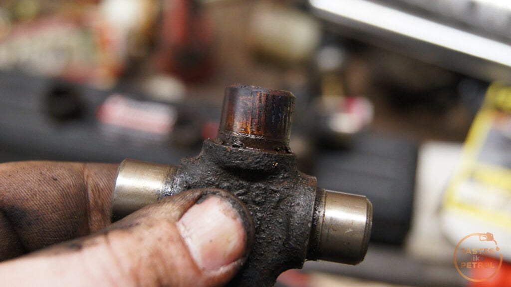
Fitting the replacement wasn't much better. This was when I was still using hammers to fit the caps and I came really stuck on this second UJ. I can only presume the caps weren't going in quite square, which meant they were binding. After a few tries I moved to the press, which only did one thing, it blew the new cap to bits.

But it also scored the cross piece
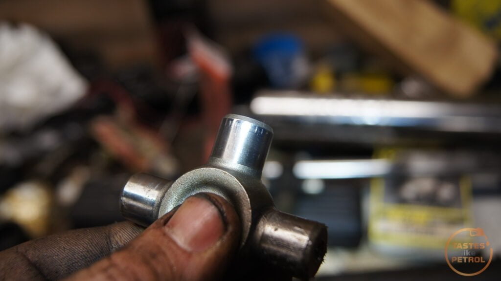
So no, I'm not perfect, I do sometimes make stupid mistakes too.
I took a little break from that UJ here as I needed another new one to continue and moved to the hanger bearing. I tore the rest of the outer part off and used a hammer and pry bar to carefully drive the old bearing off.

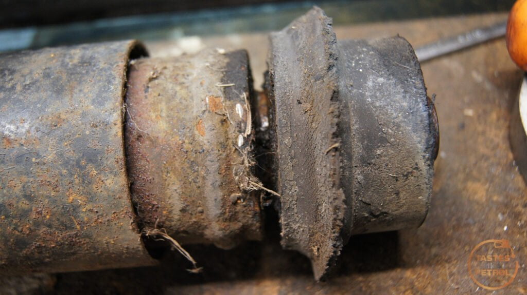
After a little bit it popped off

With the bearing off it was easier to handle, so had a go at replacing this UJ. This was the only one that is greasable, and as I later found out this is because there is a small recess in the flange to allow space for the grease nipple. You can just make the recess out here.

This was another one that I was having a battle with, but instead of trying to use more force to press it out, I just grabbed the grinder and used a cutoff wheel to make quick work of it.

Take that!
The new caps pressed in fine, using my newly honed method of starting with the flange, and pressing the caps in with my vice until they are flush, and then tapping them in the rest of the way with a socket and hammer until the clips fit in the recess. A couple of taps on the flange frees the joint up. Another rookie failure here, I didn't notice there was a recess for the grease nipple at the time, so fitted the joint in the wrong orientation. Argh.
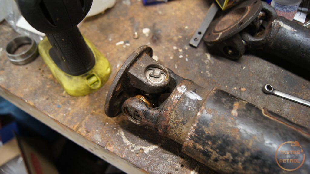
Without another new joint to replace the damaged one, the only thing I could do was fit the new center bearing. This was as easy as popping it into place, with the longer side facing the splines and then tapping it down until it bottoms out. I used a big socket and an old bearing race as a spacer.


I had a new joint arrive a couple of days later, so in that went. I initially tried fitting it to the existing flange, but it didn't feel right, so went with my gut feeling and pulled the flange off my original driveshaft, and used that instead (thankfully it was the one joint that wasn't staked). It's not ideal, but I feel like the flange may be damaged on the other one which is why I was having so much trouble.
The joints pressed in with no issue. Ignore the placeholder bolt, that was just testing it was a 6mm grease fitting thread. The other two joints were 1/4" UNF thread.
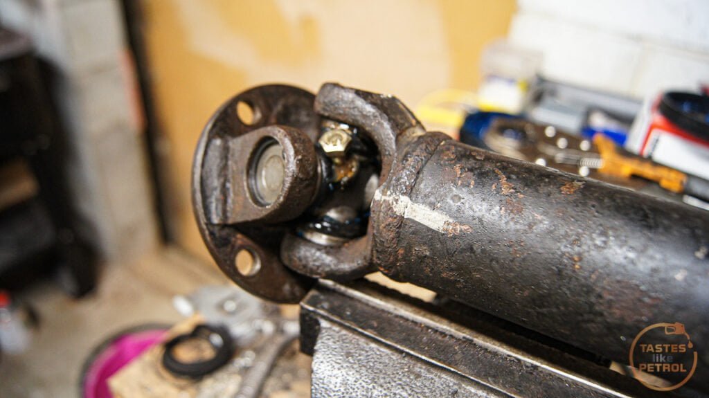
Speaking of, to sort my issue of all the grease nipple being too long and fouling the joints, I went out and bought some short grease nipples.
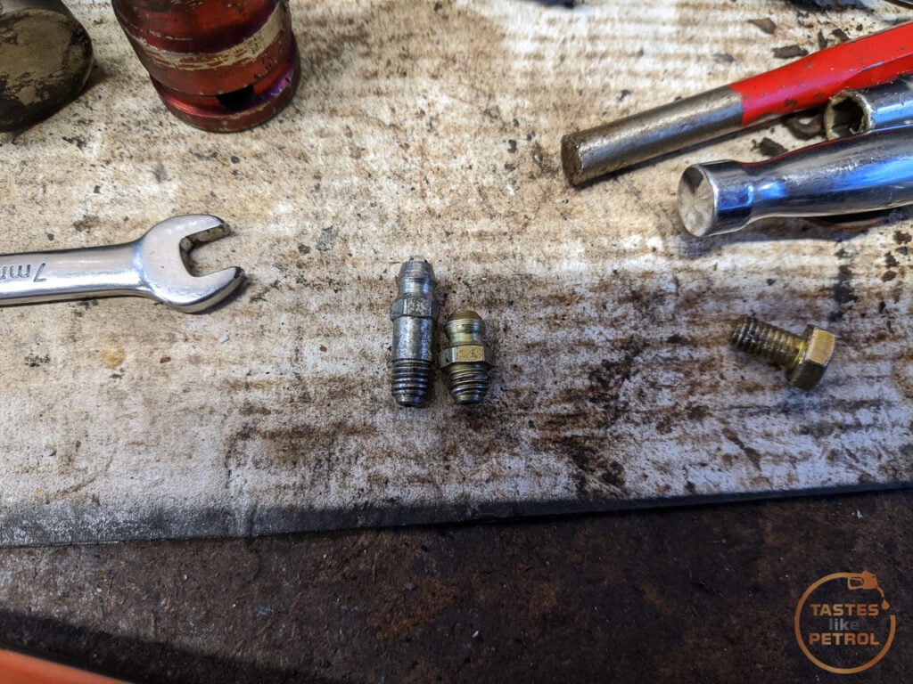
These clear with ample space, but were an utter b d to fit. They have a bigger hex than the longer ones, and there is no room to actually get anything on the hex when you screw it into the joint. I ended up tightening them up one flat at a time with the spanner sticking straight up in line with the fitting.
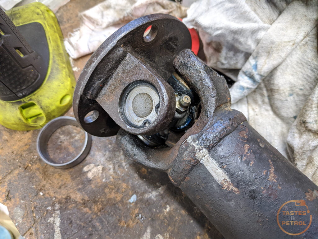
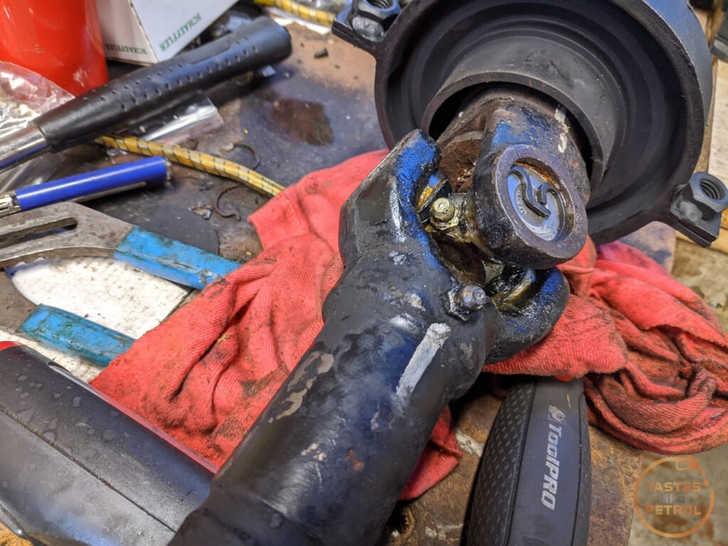
In hindsight, I would get the sealed joints, but if I couldn't, I would get some grub screws with the correct threads and use them to plug the holes after greasing. Either way, the joints are all greased, and the holes plugged.
With all the joints replaced and the new center bearing in place all I had to do now was refit the two halves of the shaft. The spline is keyed with a double width tooth, so it can only fit in one orientation. Take note before sliding the spline completely down that it's easier to start fitting the bolt in the center when the shaft is slightly apart as there is limited space with the joint in place.
I did the bolt up as tight as possible, and then bent the locking tab over.
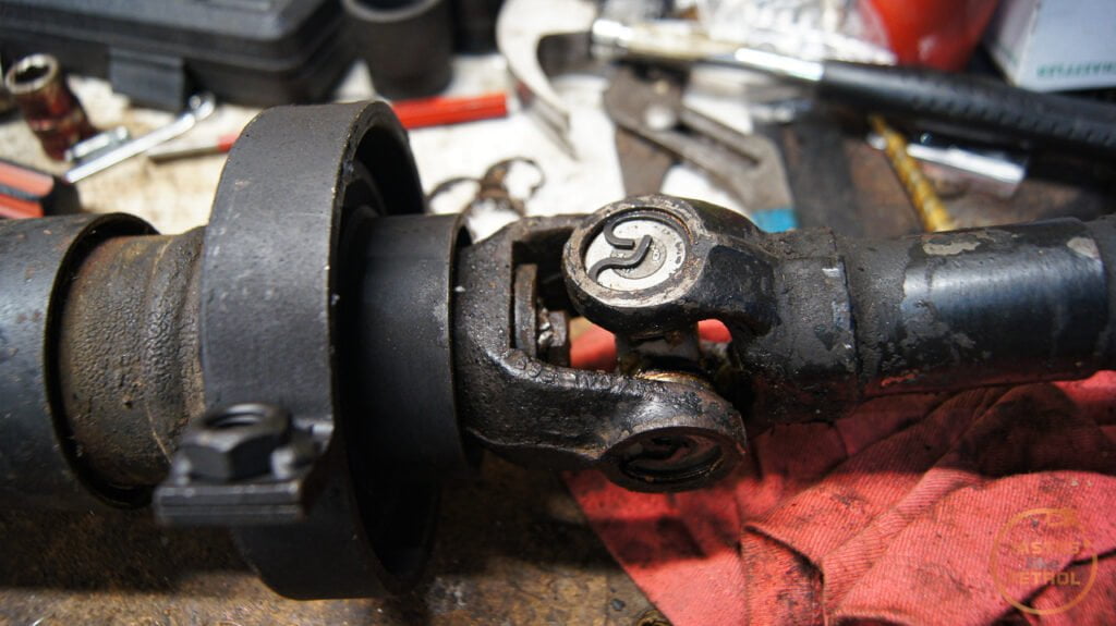
Now all I need to do is fit it back to the car, but that can happen another day since I can't be bothered rolling around on the ground right now. Once that's in, since the clutch is bled and working, all that's left is new tyres, which are currently in a stack next to the car waiting for me to strip the old tyres off and paint the wheels.

Getting real close to moving under its own power for the first time in about 25 years.
But with the Carib on the road, I turned my attention to the Marina again.
One of the things that had to be done before I could attempt to move the car under its own power was to rebuild the driveshaft/propshaft.
I knew from when I first went under the car that the center hanger bearing was completely shot, and had collapsed, so at the very least that needed to be replaced.
Ages ago (about two months ago) I slid under the car and removed the driveshaft.
Hanger bearing was looking a bit sad
I'm glad I took it out and checked, it turns out the bolt that secures the two halves together was... missing.
There was also play in at least one of the universal joints, and it wasn't the one secured by clips. Two of the three UJs are secured by a process called Staking, where they physically deform the metal around the edge of the cap to hold it in place. This is a real pain because it needs some skill and usually a bigger press than I have to replace them.
You can see better detail in this example image
A normal universal joint is secured by a big circlip in a groove, which is far easier to work with.
This prompted me to reach out to a fellow Marina owner and purchase a spare driveshaft off him, which although had a failed center bearing too, used Circlip style UJs and had the securing bolt for the two halves.
I finally got around to attacking the replacement driveshaft the other day. I wanted to refurbish the whole thing since it was old and I didn't want to have to pull it out later to replace the UJs.
There is a great video by Chris Fix on how to replace UJs. He makes it look easy, but I hated this job.
https://youtu.be/5gOeBE-ylQw
First I cleaned it up a bit, marked the alignment and removed the clips with a pair of circlip pliers
This end was pretty straightforward. Big socket (24mm impact) underneath, and a smaller one that fits into the recess (14mm impact, 16mm normal) on top and using a big hammer, smash the 14mm socket down, pushing the UJ cap out the bottom.
It came apart more or less with no trouble. Push the joint down, pull the cap out. push the joint back up, pull the cap out. Done.
To fit the new joint, I found it best to lubricate the recess you are pressing the caps into with clean ATF, and then press them both in together using a bench vice. This helps to press them in square. I didn't do this for the first couple, I used the method of hammering the new caps into place.
I did unfortunately find out why they recommend sealed joints without grease fittings... There is not enough room in the joint for the long grease fitting, and you would risk breaking the fitting off when the joint moves.
These joints were very cheap on clearance though, so I persisted anyway and dealt with that later.
One end of the driveshaft done. The new joint is smooth and feels great. A few pumps of the grease gun and it was ready for action. Kinda.
The next joint was well jammed in place, to the point it blew the end out of the cap before dislodging it
You can tell from the state of it when it did come out that had some issues. Being a sealed unit, you can't grease it, so once the grease hardened it was all bad.
Fitting the replacement wasn't much better. This was when I was still using hammers to fit the caps and I came really stuck on this second UJ. I can only presume the caps weren't going in quite square, which meant they were binding. After a few tries I moved to the press, which only did one thing, it blew the new cap to bits.
But it also scored the cross piece
So no, I'm not perfect, I do sometimes make stupid mistakes too.
I took a little break from that UJ here as I needed another new one to continue and moved to the hanger bearing. I tore the rest of the outer part off and used a hammer and pry bar to carefully drive the old bearing off.
After a little bit it popped off
With the bearing off it was easier to handle, so had a go at replacing this UJ. This was the only one that is greasable, and as I later found out this is because there is a small recess in the flange to allow space for the grease nipple. You can just make the recess out here.
This was another one that I was having a battle with, but instead of trying to use more force to press it out, I just grabbed the grinder and used a cutoff wheel to make quick work of it.
Take that!
The new caps pressed in fine, using my newly honed method of starting with the flange, and pressing the caps in with my vice until they are flush, and then tapping them in the rest of the way with a socket and hammer until the clips fit in the recess. A couple of taps on the flange frees the joint up. Another rookie failure here, I didn't notice there was a recess for the grease nipple at the time, so fitted the joint in the wrong orientation. Argh.
Without another new joint to replace the damaged one, the only thing I could do was fit the new center bearing. This was as easy as popping it into place, with the longer side facing the splines and then tapping it down until it bottoms out. I used a big socket and an old bearing race as a spacer.
I had a new joint arrive a couple of days later, so in that went. I initially tried fitting it to the existing flange, but it didn't feel right, so went with my gut feeling and pulled the flange off my original driveshaft, and used that instead (thankfully it was the one joint that wasn't staked). It's not ideal, but I feel like the flange may be damaged on the other one which is why I was having so much trouble.
The joints pressed in with no issue. Ignore the placeholder bolt, that was just testing it was a 6mm grease fitting thread. The other two joints were 1/4" UNF thread.
Speaking of, to sort my issue of all the grease nipple being too long and fouling the joints, I went out and bought some short grease nipples.
These clear with ample space, but were an utter b
d to fit. They have a bigger hex than the longer ones, and there is no room to actually get anything on the hex when you screw it into the joint. I ended up tightening them up one flat at a time with the spanner sticking straight up in line with the fitting.In hindsight, I would get the sealed joints, but if I couldn't, I would get some grub screws with the correct threads and use them to plug the holes after greasing. Either way, the joints are all greased, and the holes plugged.
With all the joints replaced and the new center bearing in place all I had to do now was refit the two halves of the shaft. The spline is keyed with a double width tooth, so it can only fit in one orientation. Take note before sliding the spline completely down that it's easier to start fitting the bolt in the center when the shaft is slightly apart as there is limited space with the joint in place.
I did the bolt up as tight as possible, and then bent the locking tab over.
Now all I need to do is fit it back to the car, but that can happen another day since I can't be bothered rolling around on the ground right now. Once that's in, since the clutch is bled and working, all that's left is new tyres, which are currently in a stack next to the car waiting for me to strip the old tyres off and paint the wheels.
Getting real close to moving under its own power for the first time in about 25 years.
One part I neglected to address in my previous post about the driveshaft was the sliding yoke. It was seized, and no amount of pretending it wasn't was freeing it up.
The sliding yoke sits at either end of the diff half of the drive shaft. Sometimes it's on the diff end of the shaft, or in my case, it's in the middle near the center bearing, depending on where BL felt like assembling it. Either way, it's a crucial part of the driveshaft.
As the rear axle travels up and down in normal driving, the rear section of the driveshaft has to raise and lower with it. The problem is that the axle travels in an arc, which means the distance from the axle to the center hanger bearing increases and decreases slightly as it moves through its travel.
To account for this change in distance, the driveshaft needs to be able to change length. This is done with the sliding yoke. Inside the yoke is a series of strong splines, which mate with another set of splines attached to the end of the driveshaft. This allows the shaft to transfer power through it via the splines, but also slide in and out to account for the movement. A cap, spring and seal stop the spline from coming all the way out.
My yoke didn't slide at all. It was completely compressed at its shortest length and would not budge. I tried many things to free it up, including filling it with penetrating oil and hitting it with various hammers. Nothing. I even tried hanging it and seeing if gravity would free it up (it didn't).

I tried a few other things with no luck, but the one thing I was lacking was tension on the spline. Hitting it to shock it was fine, but if there was no tension pulling the two halves apart then I was only going to get so far.
So I had a brainwave (it hurt).
Two ratchet straps and a very sturdy workbench later, I had this contraption

I ratchet strapped each end of the shaft to a leg of the bench and put tension on the shaft. With one hand I grabbed the yoke and leaned back, putting even more tension on the shaft. With my other hand, I hit the flat of the driveshaft with a hammer. Sure enough, after a few hits, I saw movement and then with a POP it fully extended.
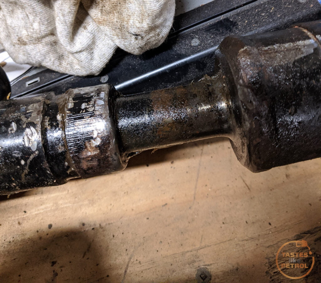
I unscrewed the cap at this point, which reveals the cork seal and washer. The cork seal is known for being pretty chewed up and is unobtainable new now. Thankfully mine was in mint condition.
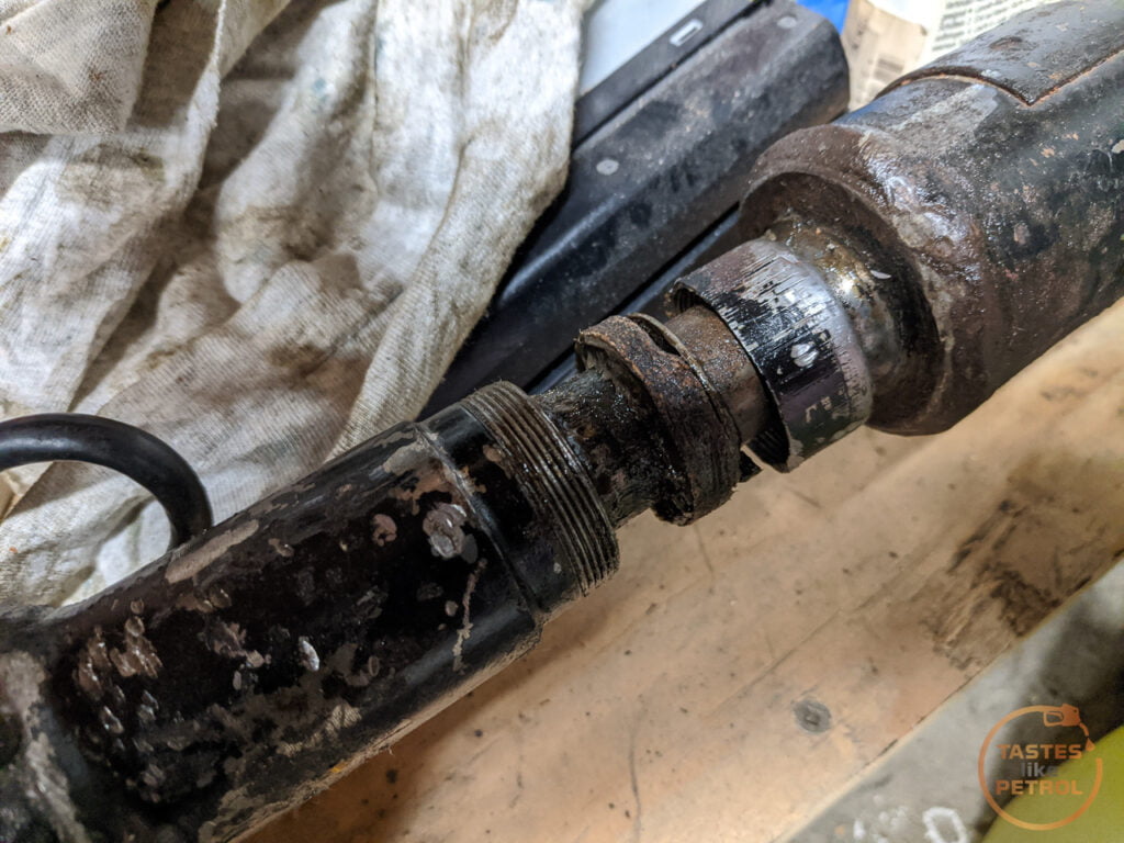
And for the first time I could see the splines. The old grease was black and disgusting, and the splines had obvious signs of surface corrosion.

One thing to make sure of is that both halves are clearly marked so it is reassembled in the same location. I scribed lines into the yoke and driveshaft and then marked it with a white paint pen.

The spline isn't keyed, so can fit many different ways. The main thing to take care of is that the UJs are in phase, which means they both have to be in line with each other.
With the spline removed it was time to get cleaning. All the old grease was cleaned off with brake cleaner and a toothbrush.
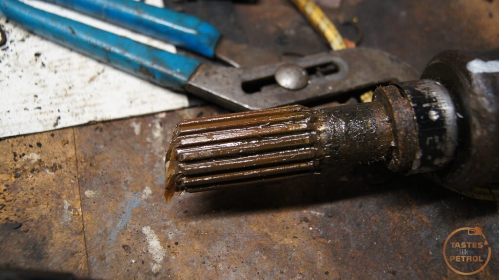
Which revealed why it was seized together. All the teeth had surface rust to some degree. This was binding with the internal splines in the yoke.

A good wiring brushing quickly got rid of most of it, showing the splines to be in good shape otherwise.
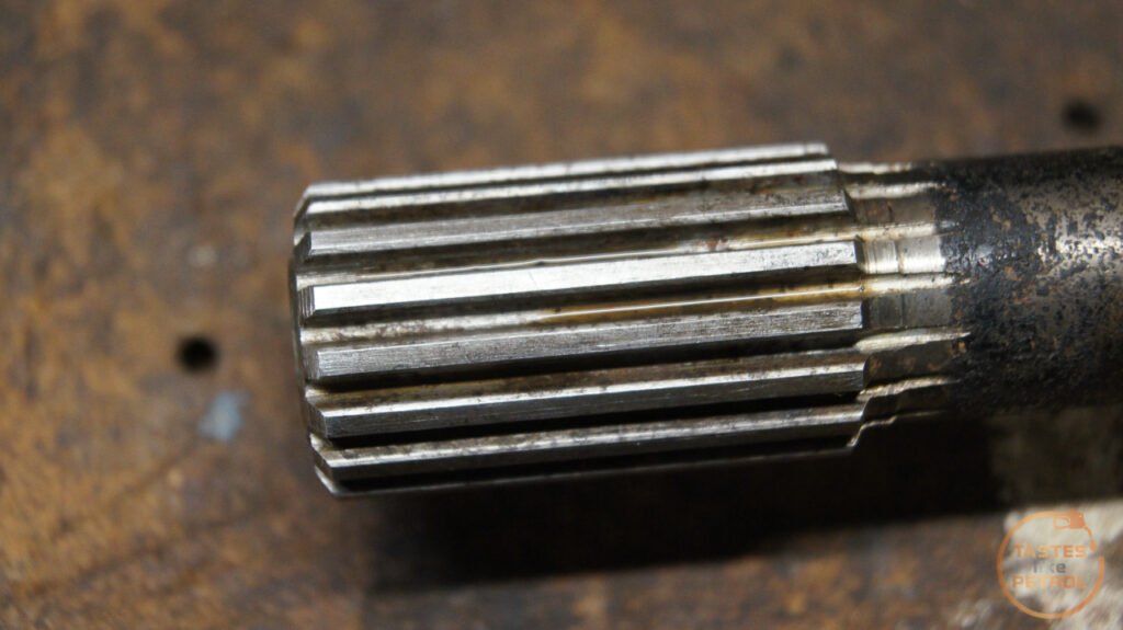
The splines were then slathered in grease ready for reassembly.

The internal splines in the yoke also got a good clean
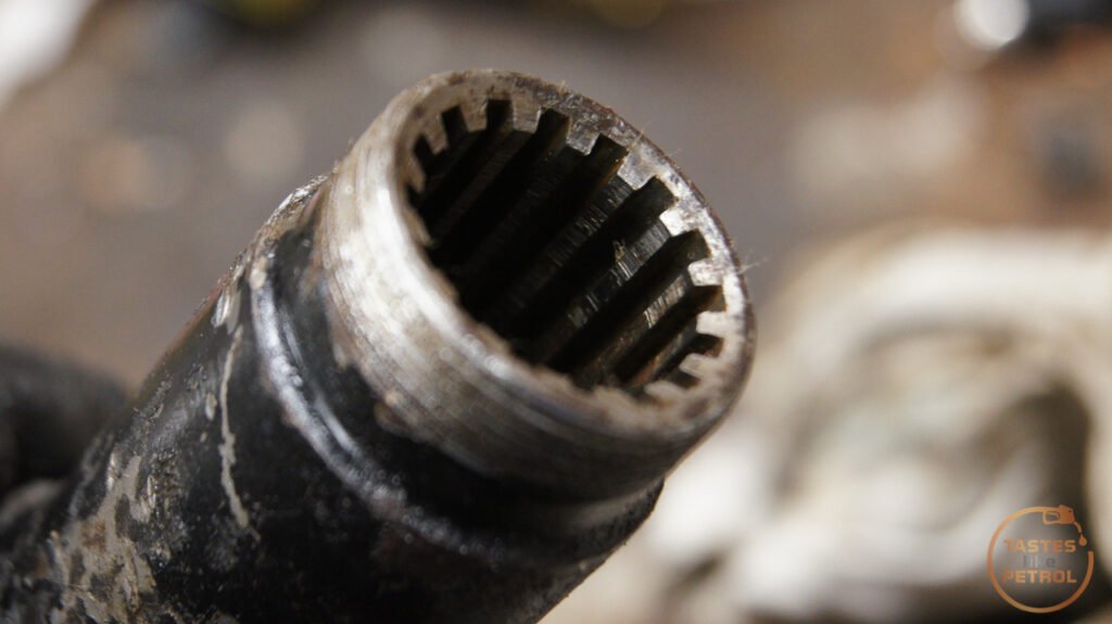
Once I was satisfied with the condition of the splines I packed the yoke with grease and slid the driveshaft back in.
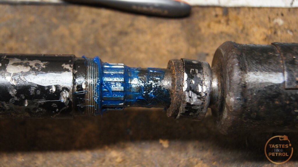
And wound the cap back down over the seal. A quick wipe to remove the grease ejected out the breather, and we're done. The joint slides freely so should do the job nicely.

With that done, the driveshaft had been completely overhauled now and is finally 100% ready to go back in the car.
The sliding yoke sits at either end of the diff half of the drive shaft. Sometimes it's on the diff end of the shaft, or in my case, it's in the middle near the center bearing, depending on where BL felt like assembling it. Either way, it's a crucial part of the driveshaft.
As the rear axle travels up and down in normal driving, the rear section of the driveshaft has to raise and lower with it. The problem is that the axle travels in an arc, which means the distance from the axle to the center hanger bearing increases and decreases slightly as it moves through its travel.
To account for this change in distance, the driveshaft needs to be able to change length. This is done with the sliding yoke. Inside the yoke is a series of strong splines, which mate with another set of splines attached to the end of the driveshaft. This allows the shaft to transfer power through it via the splines, but also slide in and out to account for the movement. A cap, spring and seal stop the spline from coming all the way out.
My yoke didn't slide at all. It was completely compressed at its shortest length and would not budge. I tried many things to free it up, including filling it with penetrating oil and hitting it with various hammers. Nothing. I even tried hanging it and seeing if gravity would free it up (it didn't).
I tried a few other things with no luck, but the one thing I was lacking was tension on the spline. Hitting it to shock it was fine, but if there was no tension pulling the two halves apart then I was only going to get so far.
So I had a brainwave (it hurt).
Two ratchet straps and a very sturdy workbench later, I had this contraption
I ratchet strapped each end of the shaft to a leg of the bench and put tension on the shaft. With one hand I grabbed the yoke and leaned back, putting even more tension on the shaft. With my other hand, I hit the flat of the driveshaft with a hammer. Sure enough, after a few hits, I saw movement and then with a POP it fully extended.
I unscrewed the cap at this point, which reveals the cork seal and washer. The cork seal is known for being pretty chewed up and is unobtainable new now. Thankfully mine was in mint condition.
And for the first time I could see the splines. The old grease was black and disgusting, and the splines had obvious signs of surface corrosion.
One thing to make sure of is that both halves are clearly marked so it is reassembled in the same location. I scribed lines into the yoke and driveshaft and then marked it with a white paint pen.
The spline isn't keyed, so can fit many different ways. The main thing to take care of is that the UJs are in phase, which means they both have to be in line with each other.
With the spline removed it was time to get cleaning. All the old grease was cleaned off with brake cleaner and a toothbrush.
Which revealed why it was seized together. All the teeth had surface rust to some degree. This was binding with the internal splines in the yoke.
A good wiring brushing quickly got rid of most of it, showing the splines to be in good shape otherwise.
The splines were then slathered in grease ready for reassembly.
The internal splines in the yoke also got a good clean
Once I was satisfied with the condition of the splines I packed the yoke with grease and slid the driveshaft back in.
And wound the cap back down over the seal. A quick wipe to remove the grease ejected out the breather, and we're done. The joint slides freely so should do the job nicely.
With that done, the driveshaft had been completely overhauled now and is finally 100% ready to go back in the car.
carinaman said:
I think I learnt on PH, possibly related to Garlick so I'll repeat it here, but the Coupe doors are the same as the saloon doors. They didn't make a longer door for the Coupe.
You are, of course, correct. Its what gives the side profile a slightly dorky unbalanced look with the long quarter window.
carinaman said:
I wonder if they considered making a hatchback Marina coupe when they did the Ital?
As the profile shot seems SAAB 900 like to me, imagine if they had done a hatchbacked Ital 3 door coupe running the Turboed A Series. Did then resident BL 5 Speed box fit the A Series bell housing?
https://farm8.static.flickr.com/7156/6738517259_30...
Interesting you mention hatchback. One Frankenstein liftback was home built at one point. Its been passed around a few owners recently, but sounds like It might be in for a restoration now. Not sure if I like it or not, but its 1 of 1, so needs to be saved.As the profile shot seems SAAB 900 like to me, imagine if they had done a hatchbacked Ital 3 door coupe running the Turboed A Series. Did then resident BL 5 Speed box fit the A Series bell housing?
https://farm8.static.flickr.com/7156/6738517259_30...
Edited by carinaman on Monday 5th July 17:32


With the driveshaft all fresh and clean, all I needed to do was crawl under the car and refit it. While under there though, I thought it prudent to replace the last remaining fluids.
Refitting the driveshaft was easy enough. I reused the old bolts but invested in some new locknuts to secure them.
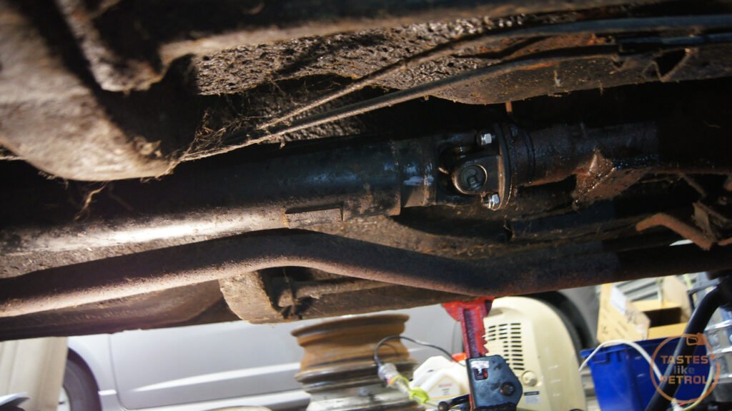
It turned out that the new center bearing has different sized captive nuts, so the old bolts wouldn't work. I got fed up with having to guess and buy bolts one by one, as all my stocks of spare bolts are of course Metric, and the Marina is Imperial, so ended up buying a kit of various sized Imperial nuts, bolts and washers from Trademe.

With the driveshaft completely refitted I moved on to changing the driveline fluids. Both the gearbox and diff call for a GL5 EP90, which as it turns out, is a bit harder to find locally. I chose to go with a Castrol Axle EPX 80W90 instead, which is a GL5 spec EP oil.

The gearbox was easy to drain and fill. The fill plug, which you should remove first, is on the RH side. Just a normal imperial square, as is the drain plug on the bottom.
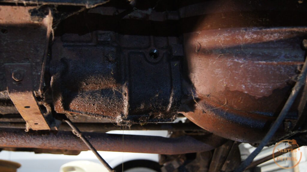
The old fluid, which has been in there for at least 25 years, wasn't as bad as it could be. It had a few years to settle at the bottom and was thick with a dark grey hue, that later changed to a dark brown. No chunks though, so that's a win.
I pumped some fresh fluid through to help shift anything sitting on the bottom, and refit the drain plug. Just a smidgen over 1L was pumped into the box, and when it started to dribble out I refit the fill plug. A quick clean and that part of the job was done.

Next was the rear diff. This was a bit of a pain as there is no drain plug, only a large fill plug.
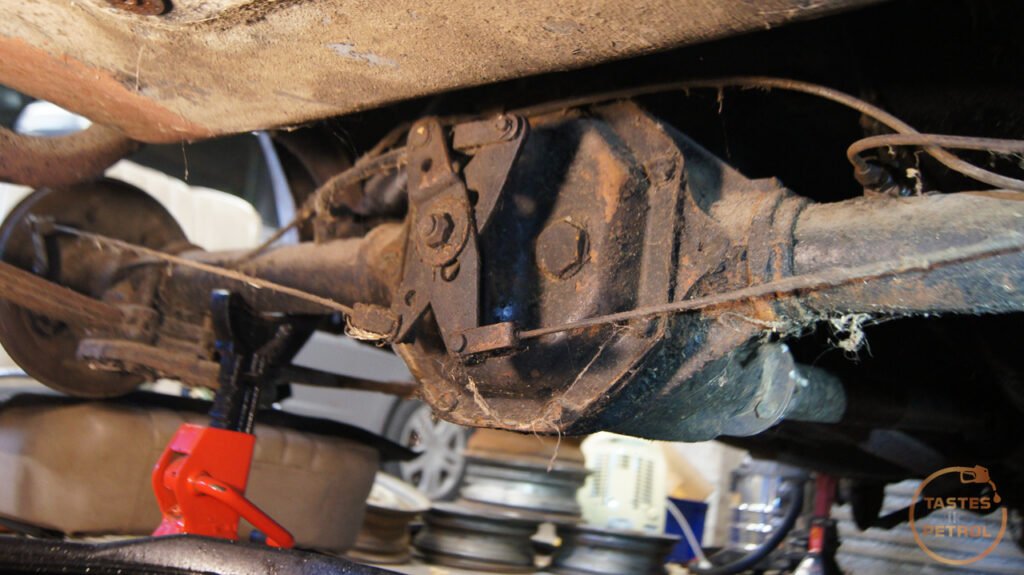
I tried a large syringe but it was taking way too long, so not wanting to be defeated, I grabbed the handheld vacuum bleeder.
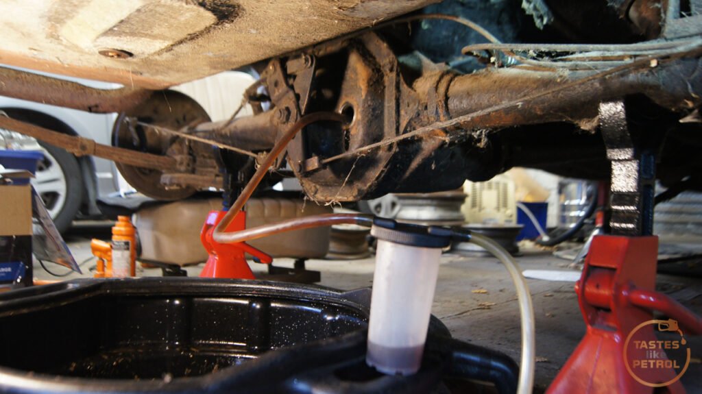
And I'll be, it worked a treat. Still slow because the waste fluid bottle is only about 100mls, but it flowed easily after a few pumps of the handle.
After getting as much as I could out, which was about 10 bottles of gross, almost black, stinky fluid that had likely been in there since it was built almost 50 years ago, I filled it with about 1L of fresh new fluid.

Once again, refit the fill plug, clean it off and done.
Now that I had the driveshaft in, I could do something that hadn't happened in a VERY long time.... see if the driveline works.
The first step was to install the pedal rubbers

Mmm fresh. I did that now, because it's way easier to do without the seat installed, which was next on the list.

What does having a seat installed mean? Sitting making vroom vroom noises of course!
Then I fired the engine up, put it into gear, and eased the clutch out.
https://youtu.be/ehoxfeG6PWo
It works! For the first time in 10-25 years, the hubs spun under their own power. Ignore the angry tractor idle, I really need to warm it up and give it a decent run, but I can't do that until we are out of the garage.
So, when is that I hear you ask. Well, the wheels need to go off and be blasted and powder coated, and then the new tyres can be fitted. Once that's done, on the car they go, and the car can FINALLY come down off the stands it's been on since I got it.
For now, I'll just be here reading my original Leyland Australia parts catalogue from 1975
Which is pretty handy really, since it shows me how things like the heater/vent ducting go together since currently it's all in a box and I had no idea.

It's completely different to the Uk cars, and the heater box is actually the same as the Aus built Mini Clubman of the time.
Soon.
Refitting the driveshaft was easy enough. I reused the old bolts but invested in some new locknuts to secure them.
It turned out that the new center bearing has different sized captive nuts, so the old bolts wouldn't work. I got fed up with having to guess and buy bolts one by one, as all my stocks of spare bolts are of course Metric, and the Marina is Imperial, so ended up buying a kit of various sized Imperial nuts, bolts and washers from Trademe.
With the driveshaft completely refitted I moved on to changing the driveline fluids. Both the gearbox and diff call for a GL5 EP90, which as it turns out, is a bit harder to find locally. I chose to go with a Castrol Axle EPX 80W90 instead, which is a GL5 spec EP oil.
The gearbox was easy to drain and fill. The fill plug, which you should remove first, is on the RH side. Just a normal imperial square, as is the drain plug on the bottom.
The old fluid, which has been in there for at least 25 years, wasn't as bad as it could be. It had a few years to settle at the bottom and was thick with a dark grey hue, that later changed to a dark brown. No chunks though, so that's a win.
I pumped some fresh fluid through to help shift anything sitting on the bottom, and refit the drain plug. Just a smidgen over 1L was pumped into the box, and when it started to dribble out I refit the fill plug. A quick clean and that part of the job was done.
Next was the rear diff. This was a bit of a pain as there is no drain plug, only a large fill plug.
I tried a large syringe but it was taking way too long, so not wanting to be defeated, I grabbed the handheld vacuum bleeder.
And I'll be, it worked a treat. Still slow because the waste fluid bottle is only about 100mls, but it flowed easily after a few pumps of the handle.
After getting as much as I could out, which was about 10 bottles of gross, almost black, stinky fluid that had likely been in there since it was built almost 50 years ago, I filled it with about 1L of fresh new fluid.
Once again, refit the fill plug, clean it off and done.
Now that I had the driveshaft in, I could do something that hadn't happened in a VERY long time.... see if the driveline works.
The first step was to install the pedal rubbers
Mmm fresh. I did that now, because it's way easier to do without the seat installed, which was next on the list.
What does having a seat installed mean? Sitting making vroom vroom noises of course!
Then I fired the engine up, put it into gear, and eased the clutch out.
https://youtu.be/ehoxfeG6PWo
It works! For the first time in 10-25 years, the hubs spun under their own power. Ignore the angry tractor idle, I really need to warm it up and give it a decent run, but I can't do that until we are out of the garage.
So, when is that I hear you ask. Well, the wheels need to go off and be blasted and powder coated, and then the new tyres can be fitted. Once that's done, on the car they go, and the car can FINALLY come down off the stands it's been on since I got it.
For now, I'll just be here reading my original Leyland Australia parts catalogue from 1975
Which is pretty handy really, since it shows me how things like the heater/vent ducting go together since currently it's all in a box and I had no idea.
It's completely different to the Uk cars, and the heater box is actually the same as the Aus built Mini Clubman of the time.
Soon.
Gassing Station | Readers' Cars | Top of Page | What's New | My Stuff