1979 Mk1 Golf 'Restomod'
Discussion


Hi everyone, I thought I'd start a thread to share and track the progress of my 1979 Mk1 Golf project.
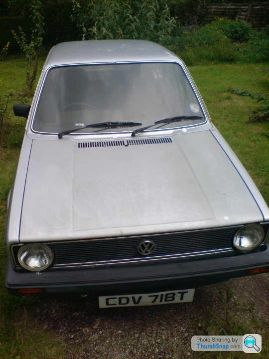
I've owned the car since 2008, bought from the local mechanic in the village I lived in with my parents in Devon. If I remember correctly I paid £350, with a fresh MOT and 36500 miles on the clock... Those were the days.... Here it is the day I brought it the 300 yard journey home

I used it daily for quite a while, and started to get involved in the local VW scene, meeting some really great people along the way, along with plenty of people who wanted to buy the car. Here it is beached on a bank following a run in with a tractor.

I did the whole ebay coilovers and wide wheels thing, ultimately resulting in this:


Good times. Late summer 2009 I decided that I was going to restore the car, so with help from a friend we built a shed for the car

I pretty quickly achieved the easy bit of taking everything apart:

And started chopping bits out, and to be perfectly honest I was pretty out of my depth at this stage:


Bought my first welder and had a go at putting some bits back in...

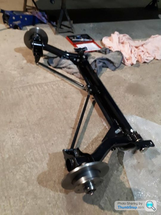
In the meantime I was also refurbishing the engine and running gear, which turned out a bit better:


I was also getting distracted with other cars, including another Mk1 Golf that was a bit of a s tter, and an E36 318is that met an untimely end about 100m from where the Golf got beached on the bank a few years earlier:


The long and short of it being that the last time the '79 was touched was Dec 2010:

Skip forward to 2012 and I decided to go back into education and started a Foundation degree in Motorsport Engineering, followed by a top up to a full degree in Automotive Engineering. This meant moving away from home, followed by getting my current job based in the Midlands. This meant that the Golf was largely forgotten about, at least until recently when my parents have moved house, meaning that I've had to bring the Golf up here.
That pretty much covers the history, the next post will go over my plans for the car and begin tracking the current work.
Thanks for reading if you made it this far!
I've owned the car since 2008, bought from the local mechanic in the village I lived in with my parents in Devon. If I remember correctly I paid £350, with a fresh MOT and 36500 miles on the clock...
Those were the days.... Here it is the day I brought it the 300 yard journey homeI used it daily for quite a while, and started to get involved in the local VW scene, meeting some really great people along the way, along with plenty of people who wanted to buy the car. Here it is beached on a bank following a run in with a tractor.
I did the whole ebay coilovers and wide wheels thing, ultimately resulting in this:
Good times. Late summer 2009 I decided that I was going to restore the car, so with help from a friend we built a shed for the car
I pretty quickly achieved the easy bit of taking everything apart:
And started chopping bits out, and to be perfectly honest I was pretty out of my depth at this stage:
Bought my first welder and had a go at putting some bits back in...
In the meantime I was also refurbishing the engine and running gear, which turned out a bit better:
I was also getting distracted with other cars, including another Mk1 Golf that was a bit of a s
tter, and an E36 318is that met an untimely end about 100m from where the Golf got beached on the bank a few years earlier:The long and short of it being that the last time the '79 was touched was Dec 2010:
Skip forward to 2012 and I decided to go back into education and started a Foundation degree in Motorsport Engineering, followed by a top up to a full degree in Automotive Engineering. This meant moving away from home, followed by getting my current job based in the Midlands. This meant that the Golf was largely forgotten about, at least until recently when my parents have moved house, meaning that I've had to bring the Golf up here.
That pretty much covers the history, the next post will go over my plans for the car and begin tracking the current work.
Thanks for reading if you made it this far!
A few weeks ago I took the trip down to Devon to drag the Golf out of the shed, and it doesn't make for a pretty sight unfortunately. The roof of the shed had failed quite a while ago, and the car was only half heartedly covered, so quite a lot of surface rust has taken hold. But there you go, can't turn the clock back, so will just have to deal with it.


Moved to it's new home, slightly better conditions than previously!

I've got some big ideas for what I want to do with the car ("Where have we heard that before?" I hear people who know me cry...! )
)
Originally I was obsessed with restoring the car to factory standard (in all of it's 1.1 engined, 4 speed gearbox glory) but to be honest I'm a different person now, with different skills and knowledge. I've never liked silver cars anyway.
So the plan is to build the car into a GTI style restomod, with a major priority being increasing chassis stiffness. Working in Chassis/Suspension design, I can see many areas in which the stiffness can be improved, so this will be the first focus whilst I'm tackling the bodywork repairs. I'm also making life harder for myself because I don't want to fit a roll cage, and want my improvements to mostly be invisible. As I go along, I'll try my best to explain why I'm making the changes I am.
I'm also contemplating making changes to the suspension and steering geometry, but I first need to analyse the existing hardpoints to get a baseline, hopefully that will be quite interesting when I get to it.
As for the rest of the car, I have a vision for how I want it to look, and I've nearly decided on an engine, but I'm not fully sure on that yet. It will certainly be naturally aspirated though, and it won't be silver!
On to the work so far.
Began by removing the remnants of the front panel so that I could clean up the inside of the crossmember, and mock up the front end to start on the alignment

Driver's side end of the crossmember needed repair, need to get better at taking before pics!


Cleaned up the inside of the crossmember with a variety of power tools and a few applications of Bilt Hamber Doex-Gel, followed by their Electrox Zinc primer, and then Epoxy primer


Lower windscreen surround was removed in preparation for repairing the inner wing tops, revealing heavy surface rust inside the pillars. This also got multiple treatments of Deox-Gel, and will get zinc and epoxy before the windscreen surround goes back on (again no before pics!)


I then turned my attention to the driver's side inner wing. No current before pictures, so here's one from 10 years ago:

There are only aftermarket repair panels available for this side and they're a disgrace, with massive wrinkles all over (thankfully a genuine one for the other side is still available; got it on backorder from Germany)

Fortunately I found a body cut from a Caddy locally on eBay, so began mocking it up

Trimmed:

Tacked in:

Bit of grinding back in between to let the next welds sit flat

More welding, taking time to allow for cooling:

Some primer on temporarily:

I haven't finished grinding everything back yet, but I hope you'll agree it's certainly a better quality repair than my previous attempt on the other side 10 years ago
That's pretty much where I'm up to now, I can't promise super speedy progress, but certainly shouldn't take another 10 years...."
Moved to it's new home, slightly better conditions than previously!
I've got some big ideas for what I want to do with the car ("Where have we heard that before?" I hear people who know me cry...!
)Originally I was obsessed with restoring the car to factory standard (in all of it's 1.1 engined, 4 speed gearbox glory) but to be honest I'm a different person now, with different skills and knowledge. I've never liked silver cars anyway.
So the plan is to build the car into a GTI style restomod, with a major priority being increasing chassis stiffness. Working in Chassis/Suspension design, I can see many areas in which the stiffness can be improved, so this will be the first focus whilst I'm tackling the bodywork repairs. I'm also making life harder for myself because I don't want to fit a roll cage, and want my improvements to mostly be invisible. As I go along, I'll try my best to explain why I'm making the changes I am.
I'm also contemplating making changes to the suspension and steering geometry, but I first need to analyse the existing hardpoints to get a baseline, hopefully that will be quite interesting when I get to it.
As for the rest of the car, I have a vision for how I want it to look, and I've nearly decided on an engine, but I'm not fully sure on that yet. It will certainly be naturally aspirated though, and it won't be silver!
On to the work so far.
Began by removing the remnants of the front panel so that I could clean up the inside of the crossmember, and mock up the front end to start on the alignment
Driver's side end of the crossmember needed repair, need to get better at taking before pics!
Cleaned up the inside of the crossmember with a variety of power tools and a few applications of Bilt Hamber Doex-Gel, followed by their Electrox Zinc primer, and then Epoxy primer
Lower windscreen surround was removed in preparation for repairing the inner wing tops, revealing heavy surface rust inside the pillars. This also got multiple treatments of Deox-Gel, and will get zinc and epoxy before the windscreen surround goes back on (again no before pics!)
I then turned my attention to the driver's side inner wing. No current before pictures, so here's one from 10 years ago:
There are only aftermarket repair panels available for this side and they're a disgrace, with massive wrinkles all over (thankfully a genuine one for the other side is still available; got it on backorder from Germany)
Fortunately I found a body cut from a Caddy locally on eBay, so began mocking it up
Trimmed:
Tacked in:
Bit of grinding back in between to let the next welds sit flat
More welding, taking time to allow for cooling:
Some primer on temporarily:
I haven't finished grinding everything back yet, but I hope you'll agree it's certainly a better quality repair than my previous attempt on the other side 10 years ago
That's pretty much where I'm up to now, I can't promise super speedy progress, but certainly shouldn't take another 10 years...."
Thanks everyone, hopefully doing this thread will encourage me to keep up a good work ethic, something I've always struggled with!
Jhonno said:
The promise is definitely there.. As long as the eBay coilovers are thrown in the bin..
Oh definitely, I have plans for the suspension, and it won't be off the shelf Mk1 Golf stuff
Love these early MK1's its the small bumpers and lights the later ones seem a bit heavy handed in comparison, early dash is great also. Look forward to following the build.
Graham Vanstone's MK1 was always a favourite, the attention to detail was like nothing else, ahead of its time really. IIRC it had a high spec NA 20v on ITB's seemed the perfect MK1 engine swap to me.
Graham Vanstone's MK1 was always a favourite, the attention to detail was like nothing else, ahead of its time really. IIRC it had a high spec NA 20v on ITB's seemed the perfect MK1 engine swap to me.


pistolpedro said:
Love these early MK1's its the small bumpers and lights the later ones seem a bit heavy handed in comparison, early dash is great also. Look forward to following the build.
Graham Vanstone's MK1 was always a favourite, the attention to detail was like nothing else, ahead of its time really. IIRC it had a high spec NA 20v on ITB's seemed the perfect MK1 engine swap to me.
Thanks, I also much prefer the early look, although a small light, small bumper GTI is a very rare thing indeed, hence deciding to make my own!Graham Vanstone's MK1 was always a favourite, the attention to detail was like nothing else, ahead of its time really. IIRC it had a high spec NA 20v on ITB's seemed the perfect MK1 engine swap to me.
tvrfan007 said:
My kind of thread.
Well done for not letting go, and I look forward to the end product featuring an rs3 engine
Thanks, funnily enough I was looking at RS3 engines on ebay the other day.... but not the right engine for this car I don't think!Well done for not letting go, and I look forward to the end product featuring an rs3 engine
smiffy77 said:
Great work so far, these can hide their rot quite well. Looking forward to seeing your suspension ideas, improvements to the mk1 chassis are well documented so will be refreshing to see a different approach. Good luck!
Cheers! Aside from the surface rust from storage, this car is acutally very good from a rot point of view, certainly better than some I've seen!Hol said:
What paint are you using to seal the cleaned up surface rusty panels?
I had a few hours on the engine bay this morning that shows quite nicely how I plan to deal with the surface rustTo start with I'm stripping the paint and bulk of the rust with various tools; poly strip discs, power file, die grinder, flap wheels, wire bushes etc.
I'm then applying Bilt Hamber Deox-Gel to clean any remaining rust out of the pits and awkward areas, leaving bright clean steel.
On the more vulnerable areas such as the engine bay, wheel arches and underside I'm then applying Bilt Hamber Electrox Zinc Primer.
This will then be overcoated with Epoxy primer (Electrox is compatible as a base for Epoxy primer and Bilt Hamber recommend to apply it first when the highest level of corrosion resistance is required) I've started with UPOL Raptor epoxy primer on the bits I've done so far but I don't really like it for two reasons. Firstly it comes out pretty much gloss which I don't suppose is really a problem, but I just don't like it. And secondly it only comes in grey, which makes it hard to see when you've got full coverage over the Electrox which is also grey. So I've ordered some HMG Epoxy primer in black to use from now on.
I seriously considered getting the shell blasted, but it's just too much of an expense for me, and would just eat into the budget for the paintwork. I've got all of the tools required to do it manually, and even if I end up spending a few hundred on Deox-Gel, it's still a lot less than it would cost at a reputable blaster. I guess the way I'm doing it is kind of like having the car dipped bit by bit (but without the negatives of dipping)
Today's work:
I've decided to work on stripping the engine bay and getting it in Epoxy first because I know it's going to be the most miserable part of the project. All that surface rust and awkward nooks and crannies to get into. Plus the fact that the original primer I used 10 years ago (Zinc 182) seems to just want to smear, even after all this time.

Deox Gel after a few day working

Cleaned off with scuff pads and the pressure washer, then rinsed down with HoldTight 102 flash rust preventative

You can see how the rust pits have been cleaned out by the gel here:

Some hard to access areas where the original seam sealer will have to stay in place. The majority of what I've removed so far has been still doing it's job well, so not too concerned about that

Back at it with the power tools to get as much as possible back to bare metal (got a 3M surface conditioning belt to try on the power file, mega! Will definitely be getting a lot more of those)

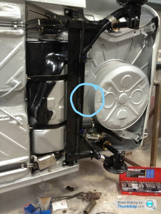
(You might notice that I've clumsily removed the engine mount and chassis leg gusset, for access and the fact the engine mount needs to be moved for the new engine. Washer bottle bracket on the inner wing will also be removed to clean behind)
Thoroughly degreased and sprayed with Electrox using a small touch up gun to get in the tight areas


A reminder of the condition I was starting with (and a mystery steering rack that some Japanese car fans might recognise)

Now just need to do the same on the other half of the engine bay!
Not the most exciting update, but it's got to be done!
I thought I'd give an update on what I've been doing on the Golf in the last week or so. Be warned, it's a long one and pretty technical.
Firstly, the actual physical work on the car.
Tried the new HMG Epoxy primer on the engine bay. Struggled a bit with getting it to spray nicely, so it ended up a bit patchy, user error.
Much happier with it than the UPol Raptor epoxy, nicer finish and cured rock hard after a few days whereas I could still mark the UPol with my finger nail after a week


Other than that I was waiting for repair panels to arrive before I could get on with the rust repair. Fortunately the passenger inner wing repair that was on backorder from Germany came in a few days ago.

The rest of the time I've been modelling the suspension to give a baseline to work from.
I'll preface this by saying that there is no 'right' answer to all of this stuff, I'm looking to make the car drive to my own tastes, which other people may not share.
There are certain characteristics that I find spoil my enjoyment of a car, which I will be trying to avoid:
Excessive impact harshness
Steering 'error states' such as kickback and tramlining
Excessively non linear yaw response
Yaw & lateral disturbance from road inputs (for example hitting a ridge/drain cover while cornering)
The causes of these things are generally separate from things like spring rate and damper settings, and are more influenced by the kinematics and compliance behaviour of the axles.
The challenge is to avoid these error states while maintaining (or ideally improving) the car's agility and engagement (what would be the point otherwise?)
With all that being said, I first worked on constructing the kinematic of the front axle, built up from a combination of my own measurements and a body repair dimension diagram.

The steering rack location is just a placeholder for now as I don't have the measurements yet, but I could start to analyse some of the geometry anyway.
Happily, once it was all built up, the track width came out within 1mm of the book figure, so hopefully that means the geometry is fairly accurate!
Without boring everyone to death with all of the detail, it's much as expected. Low caster angle (common with no power steering), with conservative geometry that will minimise error states such as torque steer and tramlining (no bad thing)
A lot of the metrics I'm looking at are influenced by ride height, which I'm yet to decide on. So as far as making any changes, that will have to wait until the ride height is set.
Moving onto the rear axle, I took a lot of measurements and modelled it in Solidworks.

The reason for making such an accurate model compared to the front is that in a twist beam suspension, the flex of the beam itself is highly influential in the control of the wheel under load (angular and linear displacements)
I also needed to know the stiffness of the body mount bushes, so waited until the girlfriend was out and rigged up a Heath Robinson rating rig on the kitchen table.


(This is obviously not how bushes are rated in real life, in particular the load I'm applying is very small, and static. Rubber has some interesting characteristics where the stiffness varies greatly with the amount of load that you apply to it, and at what frequency. But nonetheless it gives a ballpark figure to work with)
A quick calculation later and we get a value of about 1500N/mm, this is pretty stiff for such a light car. The reasons for this will become clear when we analyse the behaviour of the axle under load.
Let's see what VW themselves have to say about this axle:


Let's test it with some opposing wheel travel (to simulate roll)

The Roll steer is not actually that low in absolute terms, but it is in the wrong direction! About 6.5 deg/m of toe out, so we're off to a bad start already.
Fortunately the camber gain is in the right direction, at about -14deg/m (gaining negative camber on the outside wheel)
Next, I looked at the behaviour when when applying lateral and longitudinal loads to the wheel (deflections are magnified greatly in this image)

Unfortunately this is where things take a turn for the worse. Again, without going into detail about the exact measurements I'm making, the headlines are:
Significant toe out with lateral force (On top of the toe out roll steer. Bad for stability, and ultimately also bad for agility as the front axle will need to be 'toned down' to compensate)
Low lateral stiffness of the contact patch (bad for agility/steering response)
Very low camber stiffness (positive camber change that outweighs the negative camber gained in roll)
Toe out under braking and when hitting at impact, e.g potholes, ridges etc. (See comment about lateral toe out)
Even more toe out when applying longitudinal force to one wheel (bad for stability when braking on surfaces with different grip levels left to right)
Very high longitudinal stiffness, especially for such a light car (bad for impact harshness & noise transfer to the body)
Now none of this is surprising, in fact they're the expected characteristics of a twist beam axle (especially with the lateral section being right at the front & therefore not really contributing much to lateral stiffness)
The body mount bushes need to be stiff to keep the toe out under control, with the knock on effect to impact harshness.
More modern twist beam designs incorporate all sorts of improvements such as moving the twist beam section rearwards to make an H shape in top view, and using funky bushes that are normally soft but get stiffer with lateral load to control the toe.
Completely changing the axle & mounting points is a bit beyond what I'm comfortable with doing, so I'll need to modify the existing axle.
So what can we do to improve the situation?
The go-to solution for the Mk1 golf rear axle is to triangulate the trailing arms to the centre of the beam, like this:
However, this is only really a halfway house solution. It increases the toe and camber stiffness of the beam itself, but it is still susceptible to toe out due to the deflection of the mount bushes. Many people will counteract this by fitting stiffer mount bushes, but this will degrade the impact harshness which is not what I want.
One solution to the problem is to take inspiration from our live axle friends and triangulate the axle to the body. Vauxhall achieved this with a Watt's Linkage on the previous 2 generations of Astra:

This provides lateral stiffness very near the wheel, whilst still giving the freedom for the axle to move up and down, backwards, and roll. (The Mercedes B class also implements a similar solution)
This allows the mount bushes to be softened off considerably as the toe compliance and lateral stiffness is take care of by the Watt's Linkage.
A downside to the Watt's linkage is that in order it to stay (more or less) central to the axle with wheel travel, the pick up points on the axle need to be offset. This can be seen on the Astra here: (one side is lower that the other)

Due to the fact that the linkage will be influencing the toe and camber compliance, this could results in a slightly different response when turning left or right.
We can do a bit better than that by implementing what's know as a Mumford link, this is slightly more complex, but allows the lateral links to be symmetrical

The next difficulty with applying either of these linkages to the golf is that there is a spare wheel well slap bang in the ideal spot for the linkage (perfectly cross car, like the Astra)

Now I could just cut out or modify the spare wheel well, but that would be too easy, and where would my spare wheel go?
The next best place appears to be a handily located cross member just ahead of the spare wheel well.
The downsides of locating the pivot ahead of the wheel centre are that the lateral links will be less stiff due to the angle on them, and the kinematics of the linkage become a bit more difficult.
To begin to understand exactly how it works, I roughly drew it up and added it to the rear axle model. I havent measured the car yet, so it's all just placed roughly in the right area.

I had to split the axle in half to allow the kinematic to move, the pivot between the two halves is located on the neutral axis of the beam (location confirmed with some FEA)

I quickly found that the linkage was generating a lot of roll steer (toe in at least, but way too much)
A lot of head scratching and fiddling later and I started to understand the mechanisms behind it and could begin to tune it.
In reality, the behaviour will not be quite the same as in the kinematic, as the pivot of the mount bushes is not in the same place as the neutral axis of the beam. I'll therefore need to build in some adjustability to the linkage for fine tuning on the vehicle.
There is also scope to tune the position of where the links joint the axle to influence the toe and camber compliance values, I'll do most of this in the Solidworks simulation.
So having done all that, I compared the performance with the Mumford link (with softer mount bushes included) to the baseline.

The results showed that it works well:
Toe out with lateral force reduced to almost zero (tuning of the link location could even turn this to toe in)
Contact patch stiffness increased 3 fold
Camber stiffness increased by 20% (can be increased further by lowering the pickup point towards the contact patch, although this will be a trade off with Roll steer)
Toe out with longitudinal force also reduced near to zero
Longitudinal stiffness halved (good for impact harshness, but will need care not do introduce longitudinal dynamic shake)
So there we go, sorry for the long and (very) dry post. As someone who does this kind of work every day it's hard to know what level of detail is interesting and what's just plain boring, so please give me feedback! It at least gives an insight into the work that goes into designing suspension!
I'll try and do some welding this week!
Firstly, the actual physical work on the car.
Tried the new HMG Epoxy primer on the engine bay. Struggled a bit with getting it to spray nicely, so it ended up a bit patchy, user error.
Much happier with it than the UPol Raptor epoxy, nicer finish and cured rock hard after a few days whereas I could still mark the UPol with my finger nail after a week
Other than that I was waiting for repair panels to arrive before I could get on with the rust repair. Fortunately the passenger inner wing repair that was on backorder from Germany came in a few days ago.
The rest of the time I've been modelling the suspension to give a baseline to work from.
I'll preface this by saying that there is no 'right' answer to all of this stuff, I'm looking to make the car drive to my own tastes, which other people may not share.
There are certain characteristics that I find spoil my enjoyment of a car, which I will be trying to avoid:
Excessive impact harshness
Steering 'error states' such as kickback and tramlining
Excessively non linear yaw response
Yaw & lateral disturbance from road inputs (for example hitting a ridge/drain cover while cornering)
The causes of these things are generally separate from things like spring rate and damper settings, and are more influenced by the kinematics and compliance behaviour of the axles.
The challenge is to avoid these error states while maintaining (or ideally improving) the car's agility and engagement (what would be the point otherwise?)
With all that being said, I first worked on constructing the kinematic of the front axle, built up from a combination of my own measurements and a body repair dimension diagram.
The steering rack location is just a placeholder for now as I don't have the measurements yet, but I could start to analyse some of the geometry anyway.
Happily, once it was all built up, the track width came out within 1mm of the book figure, so hopefully that means the geometry is fairly accurate!
Without boring everyone to death with all of the detail, it's much as expected. Low caster angle (common with no power steering), with conservative geometry that will minimise error states such as torque steer and tramlining (no bad thing)
A lot of the metrics I'm looking at are influenced by ride height, which I'm yet to decide on. So as far as making any changes, that will have to wait until the ride height is set.
Moving onto the rear axle, I took a lot of measurements and modelled it in Solidworks.
The reason for making such an accurate model compared to the front is that in a twist beam suspension, the flex of the beam itself is highly influential in the control of the wheel under load (angular and linear displacements)
I also needed to know the stiffness of the body mount bushes, so waited until the girlfriend was out and rigged up a Heath Robinson rating rig on the kitchen table.
(This is obviously not how bushes are rated in real life, in particular the load I'm applying is very small, and static. Rubber has some interesting characteristics where the stiffness varies greatly with the amount of load that you apply to it, and at what frequency. But nonetheless it gives a ballpark figure to work with)
A quick calculation later and we get a value of about 1500N/mm, this is pretty stiff for such a light car. The reasons for this will become clear when we analyse the behaviour of the axle under load.
Let's see what VW themselves have to say about this axle:
Let's test it with some opposing wheel travel (to simulate roll)
The Roll steer is not actually that low in absolute terms, but it is in the wrong direction! About 6.5 deg/m of toe out, so we're off to a bad start already.
Fortunately the camber gain is in the right direction, at about -14deg/m (gaining negative camber on the outside wheel)
Next, I looked at the behaviour when when applying lateral and longitudinal loads to the wheel (deflections are magnified greatly in this image)
Unfortunately this is where things take a turn for the worse. Again, without going into detail about the exact measurements I'm making, the headlines are:
Significant toe out with lateral force (On top of the toe out roll steer. Bad for stability, and ultimately also bad for agility as the front axle will need to be 'toned down' to compensate)
Low lateral stiffness of the contact patch (bad for agility/steering response)
Very low camber stiffness (positive camber change that outweighs the negative camber gained in roll)
Toe out under braking and when hitting at impact, e.g potholes, ridges etc. (See comment about lateral toe out)
Even more toe out when applying longitudinal force to one wheel (bad for stability when braking on surfaces with different grip levels left to right)
Very high longitudinal stiffness, especially for such a light car (bad for impact harshness & noise transfer to the body)
Now none of this is surprising, in fact they're the expected characteristics of a twist beam axle (especially with the lateral section being right at the front & therefore not really contributing much to lateral stiffness)
The body mount bushes need to be stiff to keep the toe out under control, with the knock on effect to impact harshness.
More modern twist beam designs incorporate all sorts of improvements such as moving the twist beam section rearwards to make an H shape in top view, and using funky bushes that are normally soft but get stiffer with lateral load to control the toe.
Completely changing the axle & mounting points is a bit beyond what I'm comfortable with doing, so I'll need to modify the existing axle.
So what can we do to improve the situation?
The go-to solution for the Mk1 golf rear axle is to triangulate the trailing arms to the centre of the beam, like this:
However, this is only really a halfway house solution. It increases the toe and camber stiffness of the beam itself, but it is still susceptible to toe out due to the deflection of the mount bushes. Many people will counteract this by fitting stiffer mount bushes, but this will degrade the impact harshness which is not what I want.
One solution to the problem is to take inspiration from our live axle friends and triangulate the axle to the body. Vauxhall achieved this with a Watt's Linkage on the previous 2 generations of Astra:
This provides lateral stiffness very near the wheel, whilst still giving the freedom for the axle to move up and down, backwards, and roll. (The Mercedes B class also implements a similar solution)
This allows the mount bushes to be softened off considerably as the toe compliance and lateral stiffness is take care of by the Watt's Linkage.
A downside to the Watt's linkage is that in order it to stay (more or less) central to the axle with wheel travel, the pick up points on the axle need to be offset. This can be seen on the Astra here: (one side is lower that the other)
Due to the fact that the linkage will be influencing the toe and camber compliance, this could results in a slightly different response when turning left or right.
We can do a bit better than that by implementing what's know as a Mumford link, this is slightly more complex, but allows the lateral links to be symmetrical
The next difficulty with applying either of these linkages to the golf is that there is a spare wheel well slap bang in the ideal spot for the linkage (perfectly cross car, like the Astra)
Now I could just cut out or modify the spare wheel well, but that would be too easy, and where would my spare wheel go?
The next best place appears to be a handily located cross member just ahead of the spare wheel well.
The downsides of locating the pivot ahead of the wheel centre are that the lateral links will be less stiff due to the angle on them, and the kinematics of the linkage become a bit more difficult.
To begin to understand exactly how it works, I roughly drew it up and added it to the rear axle model. I havent measured the car yet, so it's all just placed roughly in the right area.
I had to split the axle in half to allow the kinematic to move, the pivot between the two halves is located on the neutral axis of the beam (location confirmed with some FEA)
I quickly found that the linkage was generating a lot of roll steer (toe in at least, but way too much)
A lot of head scratching and fiddling later and I started to understand the mechanisms behind it and could begin to tune it.
In reality, the behaviour will not be quite the same as in the kinematic, as the pivot of the mount bushes is not in the same place as the neutral axis of the beam. I'll therefore need to build in some adjustability to the linkage for fine tuning on the vehicle.
There is also scope to tune the position of where the links joint the axle to influence the toe and camber compliance values, I'll do most of this in the Solidworks simulation.
So having done all that, I compared the performance with the Mumford link (with softer mount bushes included) to the baseline.
The results showed that it works well:
Toe out with lateral force reduced to almost zero (tuning of the link location could even turn this to toe in)
Contact patch stiffness increased 3 fold
Camber stiffness increased by 20% (can be increased further by lowering the pickup point towards the contact patch, although this will be a trade off with Roll steer)
Toe out with longitudinal force also reduced near to zero
Longitudinal stiffness halved (good for impact harshness, but will need care not do introduce longitudinal dynamic shake)
So there we go, sorry for the long and (very) dry post. As someone who does this kind of work every day it's hard to know what level of detail is interesting and what's just plain boring, so please give me feedback! It at least gives an insight into the work that goes into designing suspension!
I'll try and do some welding this week!
Thank you for the positive comments!
I just found your Fiesta thread, amazing work. We seem to share a similar philosophy when it comes to modifying bland hatchbacks!
A multilink rear axle would of course bring some further benefits, but for me the body modifications needed outweighs the benefits. There would also be quite a large weight penalty by using the Mk5 axle, and I've got a weight target for the car that will be a stretch anyway.
mwstewart said:
Excellent shell preparation work! Really not tempted with the Mk5 Golf IRS then?
Thanks, it's a bit laborious but will hopefully mean that the end product lasts!I just found your Fiesta thread, amazing work. We seem to share a similar philosophy when it comes to modifying bland hatchbacks!
A multilink rear axle would of course bring some further benefits, but for me the body modifications needed outweighs the benefits. There would also be quite a large weight penalty by using the Mk5 axle, and I've got a weight target for the car that will be a stretch anyway.
I can't claim to understand everything but it's interesting and informative nontheless.
In the last Solidworks grab you appear to have moved the links forward, is the spare wheel well going to have to go after all or will they still fit round it (I like the philosphy you're taking BTW)?
In the last Solidworks grab you appear to have moved the links forward, is the spare wheel well going to have to go after all or will they still fit round it (I like the philosphy you're taking BTW)?
Gassing Station | Readers' Cars | Top of Page | What's New | My Stuff