Discussion


Yes, I have always welded a sacrificial 3x3 angle plate3 to the top and bottom of the central chassis section, cropped of each side (enough to drop a 10mm drill through), made the new central section with chamfered/gapped and 10mm drill holes, and extensions to the outriggers then created two inner tubes, and puddle TIG'd the 10mm holes and all the through to the inners (through chamfer/gap). I TIG copper/bronze my work and dress everything back to invisible ( I know when I get to steel as it sparks). A@
Adrian@ said:
Yes, I have always welded a sacrificial 3x3 angle plate3 to the top and bottom of the . A@
Okay, so that’s if your replacing the centre section too, assume you’ve chopped the outriggers off at this point and position your new centre piece and knock the insert splice in from the chopped off outrigger side, leaving a length protruding to weld the new outrigger onto as well, then weld up. So this leaves a portion of the original outrigger, let’s say 50mm for example sticking out each side of the main chassis (probably 100mm on the outrigger side). If you are just doing the outriggers then similar operation, with the splices but just to the outside and no need for the 3x3 angle.
Pretty much...adding 15mm press plated folds to the shell mounts and plasma cutting off 13mm (to give them a lip) then infilling the undercut with bronze where the flat plates meet a round tube, blanking off the voids in seat belt mounts, (I have made them in S/S in the dim distant past). A@
Adrian@ said:
Pretty much...adding 15mm press plated folds to the shell mounts and plasma cutting off 13mm (to give them a lip) then infilling the undercut with bronze where the flat plates meet a round tube, blanking off the voids in seat belt mounts, (I have made them in S/S in the dim distant past). A@
Some good tips there. Thanks. The method that Shaun has used is the very best engineered solution I have seen. Note the three bolt fastening which deals with the stress issue I referred to. If I was to cut out this member on my car this is the only way I have seen that I would consider. Proper understanding of the issues. Proper job!
greymrj said:
The method that Shaun has used is the very best engineered solution I have seen. Note the three bolt fastening which deals with the stress issue I referred to. If I was to cut out this member on my car this is the only way I have seen that I would consider. Proper understanding of the issues. Proper job!
Well done ..back on topic..agreed. A@
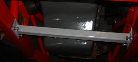

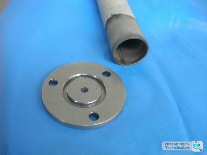
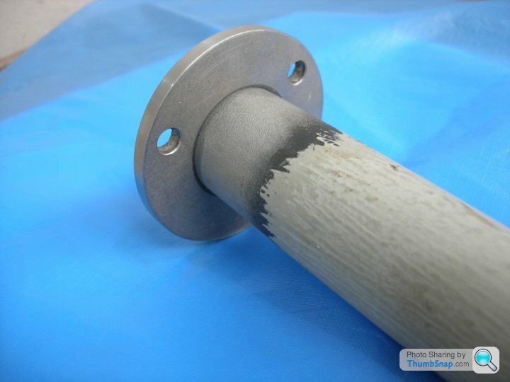
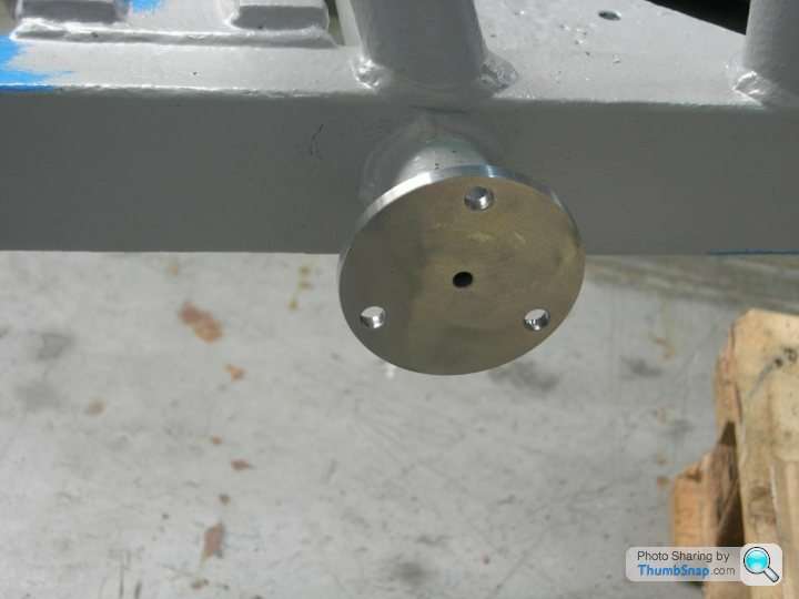
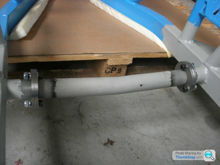
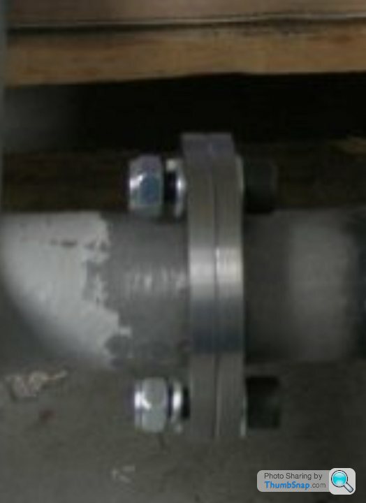
This is what I did on the S1:
Was simple to do in-situ, and no issues to date. I know it's not moving, because I paint-marked it. Its primary function is to resist tension, due to the weight of the engine bobbing up and down as you drive along. You could cut it out completely, and likely notice no difference. The V8S has a totally different X-brace arrangement, mounted further forward.
Have done others (under my Southways banner) which were different designs, like a threaded plate welded to the rails.
Did this to my S3c ages ago when the big ends nipped up. Went on 3 tours, Italy and back, 3 track days and it didn't fall off or bend once..!! 
https://www.pistonheads.com/gassing/topic.asp?h=0&...
https://www.pistonheads.com/gassing/topic.asp?h=0&...
GreenV8S said:
Looks like a perfectly good solution for that problem. It occurs to me that turning the flanges through 90 degrees would enable it to also resist axial twisting in the chassis rails i.e. the outriggers trying to move up and down.
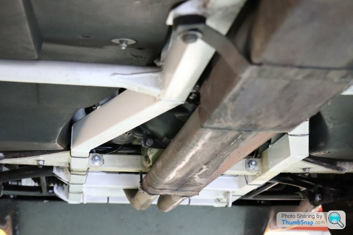
It would, but it wouldn't be possible to get to the top of the bracket to weld it properly, what with everything else in-situ. With the bracket this way round, I was able to weld the top in between the eyelets.Originally I had ideas to have two bolts in each eyelet, mounted at 45degrees to each other, which would have stopped any torsional movement, but I really don't think it's as big an issue as people are making out. These chassis' aren't exactly precision engineered! I've had chassis' through the doors here where the outrigger on one side is 20mm higher than the other, because the holes in the lower rails were drilled at different heights, and the kink in the tube was in the wrong place!
The fact that subsequent chassis' ditched this design is probably telling.
I think it's only there because its was easier to get things (somewhere near) straight and level when building the chassis to push one length of tube straight through?
But I guess there is some logic in that it helps prevent the main chassis rails splaying out under the not inconsiderable weight of the engine


Gassing Station | S Series | Top of Page | What's New | My Stuff