Discussion


Its been slow progress over winter as I am working outside in a very wet part of Lancashire but better weather and a bit of cover has spurred me on
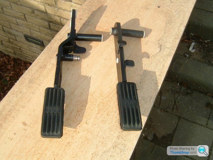
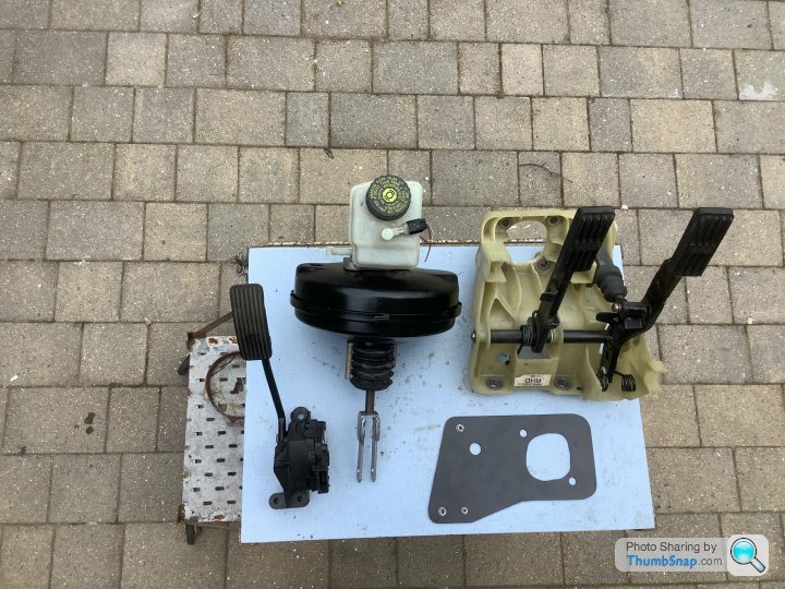
I didn't like the clutch slave cylinder on the S and mine was shot any way, also I am going fly by wire on the throttle so be losing the accelerator pedal so looked at the donor Jag pedal box which wasn't so different ?
I decided to go for it and modify both the Jag Pedals and the S bulkhead and fit the Jag pedal box
Finally got around to doing more work on my car.
Next job was installing an alternator into the small gap on the left of the engine.
First I tried the Jag alternator but due to its mounting lugs couldn’t even pass it thru the hole between the chassis’s and engine so no good.
I had a Mondeo alternator off the sump donor engine and this did fit and was very close to lining up but the gaps around alternator were just too small, but least I knew the size of body I needed.
After lots of internet research I decided on Ford Transit Connect alternator which has a small body but has a good output (130 A). Unfortunately this is a “smart” alternator which is controlled by the cars ECU so I am going to have to get it converted to become a standard “dumb” device.
I found it quite difficult to position the unit correctly to make measurements but made some cardboard templates for suitable brackets and after a few revisions made these brackets to bolt on the engine block which provide mounts for alternator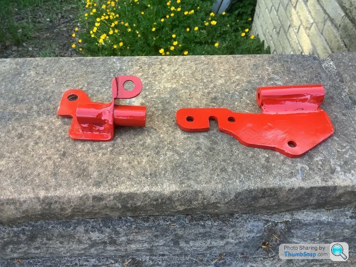
Welding again is not so neat but quite secure !
After fitting and removing the engine numerous times without the alternator fitted I was able to finalise and confirm it would fit then started working out the belt.
I stole an idea of someone else’s engine conversion and used a Range Rover P38 adjustable air con pulley as a tensioner which required a spacer machining to enable it to bolt thru a M8 hole on the front engine cover.
I measured the belt length using a flat tape measure at around 1080 mm then made a quessimate to the required belt length available which ended up as a 6PK1076 belt.
I fitted the engine again !
It’s a bit of a faff trying to fit the alternator, I had to fit the top bracket to the engine then fit the alternator then install the bottom bracket whilst lifting the engine slightly to get the bottom bolt over the chassis rail but it all went in.
Although it all fitted ok I wasn’t happy with the clearance between the pulley and the upright chassis rail, thinking that any engine movement might cause it to clash, so out with the engine again and I “scolloped” out the chassis rail slightly (about 10mm) which now give lots of clearance.[url]

Not posted for awhile but project still ongoing !
Thought i would have a look at the fuel tank as i want to use the S Type Jag intank fuel pump.
I cant remember if I drained tank or it was already empty when I got the car but dropped it out and had a peek inside !!!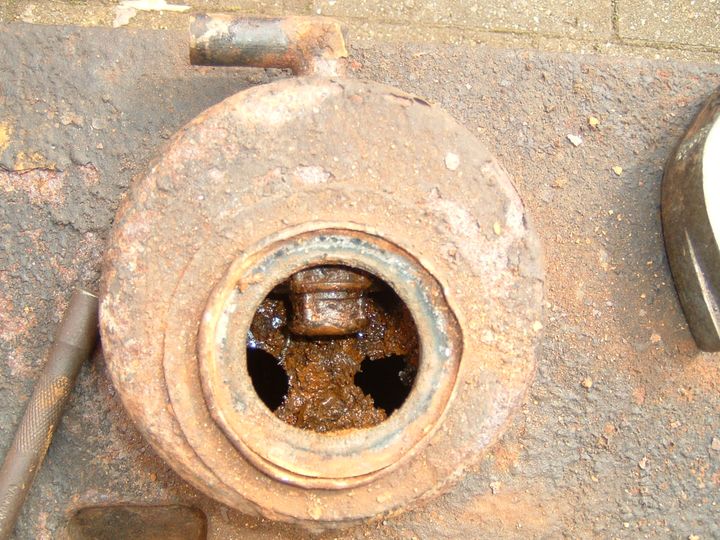
Time for a new tank I think
Thought i would have a look at the fuel tank as i want to use the S Type Jag intank fuel pump.
I cant remember if I drained tank or it was already empty when I got the car but dropped it out and had a peek inside !!!
Time for a new tank I think
After a lot of procrastination finally decided on method of mounting the inlet manifold.
First idea was to get an adapters machined out of billets of aluminium so I drew a sketch of the Jag lower inlet and the Ford Mondeo/Cougar 2.5 ltr manifold and was going to get it drawn in cad but that’s as far as I got !
Then it was suggested that it would be possible to get it 3D printed in high temp plastic and managed to get a base drawing off someone already doing the same conversion. My problem with this method was it was going to be printed by a friend of a friend remotely so I would have no control over the process .
Eventually decided to just do it.
I needed to adapt from Jag to Ford so what I did was cut 20mm slice from the bottom of the original Jag S type manifold and bought the cheapest Mondeo/Cougar ST200 V6 upper svt intake manifold and took a 30mm slice off the top.The Jag lower was bolted to a Mondeo lower intake manifold which is the same pattern as the Jag and the upper Ford intake was bolted to the air intake manifold.These were aligned as best I could the welded together( this took ages as I cannot Tig weld ! )
The final result is ok and I am happy enough with them and think it will work ok.
Hi, Looks like a great project. I'm doing something similar, but with the V8 version of this engine. I've noticed you've got the same problem as me in that the gearbox outlet is for a rubber Guibo. Just wondering what your plans are for that? I'm thinking of doing a two-piece prop. Will be fabricating that this weekend to see how it all looks.
Decided it was time to try to fit the bonnet.
My project car came with the bonnet already removed so didn’t know how well it fitted originally.
After numerous disappointing attempts to fit and align the bonnet correctly it turns out they don’t always fit that well!
Decided to bin the original hinges and started looking round at other people’s solutions of getting the bonnet to open a little bit wider.
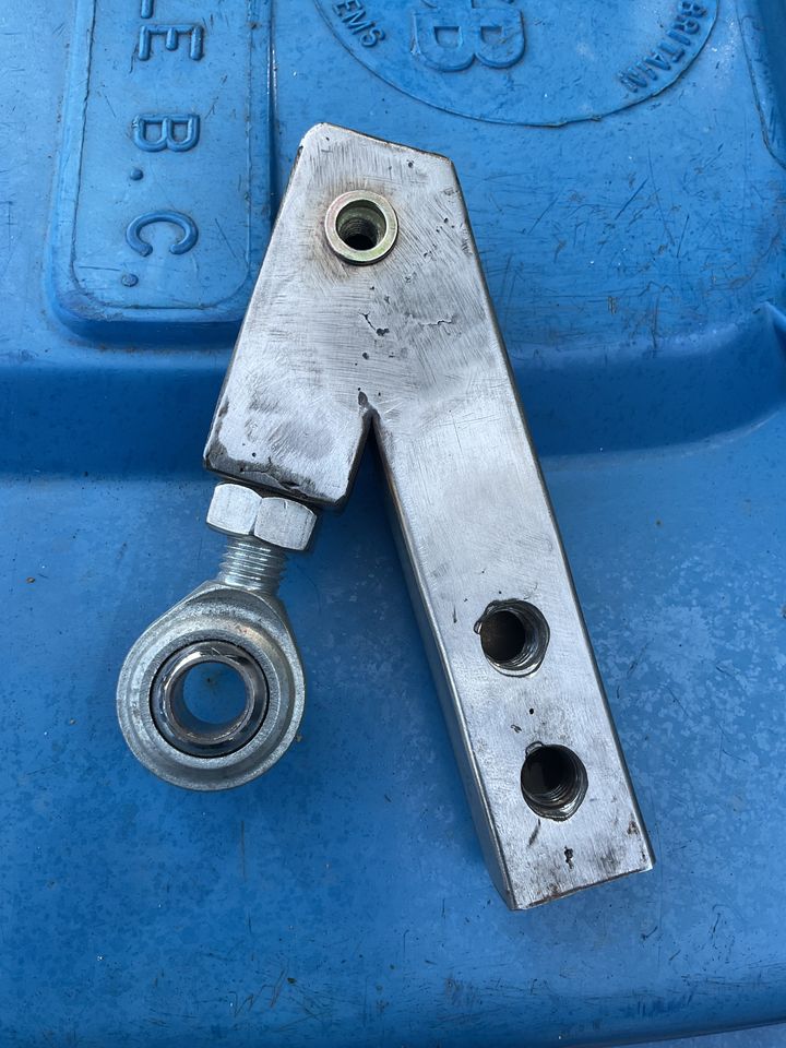
Bob Honnor was kind enough to send me all his amazing comprehensive drawings of his design which I decided to use but adapted to make it easier for me to make with my limited fabrication/welding skills.
I made the chassis part of the hinge out of stainless steel box section using dimensions gleaned from Bob’s drawing.
I had to replace the rotten plywood bonnet webs which gave me more material around the new pivot point.
The bonnet part of the hinge is BMW Mini top mounts with the studs punched out.
These fit together with 2 M14 bolts, I also added gas struts from my donor S type as I already had them.
I also decided to trim the inside lower edge of the bonnet to allow more opening angle, the whole bonnet needs a respray eventually.
My project car came with the bonnet already removed so didn’t know how well it fitted originally.
After numerous disappointing attempts to fit and align the bonnet correctly it turns out they don’t always fit that well!
Decided to bin the original hinges and started looking round at other people’s solutions of getting the bonnet to open a little bit wider.
Bob Honnor was kind enough to send me all his amazing comprehensive drawings of his design which I decided to use but adapted to make it easier for me to make with my limited fabrication/welding skills.
I made the chassis part of the hinge out of stainless steel box section using dimensions gleaned from Bob’s drawing.
I had to replace the rotten plywood bonnet webs which gave me more material around the new pivot point.
The bonnet part of the hinge is BMW Mini top mounts with the studs punched out.
These fit together with 2 M14 bolts, I also added gas struts from my donor S type as I already had them.
I also decided to trim the inside lower edge of the bonnet to allow more opening angle, the whole bonnet needs a respray eventually.


Gassing Station | S Series | Top of Page | What's New | My Stuff