Another mystery car
Discussion


Who would ever have thought when they built that car, or drive it in London that it would inspire so many superb and interesting posts so many years on.
Given the skill displayed on this thread over the years and wealth of knowledge, we really ought to set about crowdfunding a recreation of this car as the only way to finally deliver an answer to the original question.
Given the skill displayed on this thread over the years and wealth of knowledge, we really ought to set about crowdfunding a recreation of this car as the only way to finally deliver an answer to the original question.

Loose_Cannon said:
Every time I see our little blue car I'm reminded of the Bristol Fighter which was a "modern" car born of the same rather antiquated concept. Never a fan when it appeared, I'm beginning to feel a bit more charitable and nostalgic towards it now.
That's because as we age, we all lose a little brain matter.As interesting as it would be to recreate it, I'm not sure if it would get us any closer to answering the original question.
Borrani72's excellent detective work however must have edged us a little closer.
The Bristol Fighter always seems to me to be one of those cars designed by two people - a beautifully sculpted rear end mated to a 'can't really be bothered' front end.
Borrani72's excellent detective work however must have edged us a little closer.
The Bristol Fighter always seems to me to be one of those cars designed by two people - a beautifully sculpted rear end mated to a 'can't really be bothered' front end.
DaveGoddard, you make an excellent point. There are quite a few clubs for Austin Sevens, and in thedugmaster's earlier link to individual car records there are so many unfamiliar terms and abbreviations ('Austin Seven' is practically a language in its' own right), that I think the best place to start would be an e-mail to The Austin 7 Special Register, and to the 750 Motor Club, inviting them to join in with us here.
I'll get on to this as soon as time allows.
This all fits with what he recalls. Does anybody have any idea which street he may be describing? This part of London is filled with tourists – somebody would have taken photo's, intentionally or otherwise, if we knew which street(s) to look at.
Vere Street today is one-way. Was this the case as far back as 1962?
I'm also wondering about the side-lights and indicators. The indicators may be hidden between the overriders, but would the side-lights be legal that close together? Would it pass an MOT if they were?
If not, then maybe this was an early, daylight, test-run before all the details were completed.
When did side-lights become a legal requirement in the UK? Could the donor car be exempt side-lights and indicators because of its' age? (Having said that, hand signals wouldn't be easy with no opening windows and gullwing doors!)
I'll get on to this as soon as time allows.
piper said:
Wow this is spooky and it is now driving me mad to. I have always loved specialist cars but I do not know this one at all, however as a car mad teenager in the early – mid 1970s I used to catch a coach from Colchester to Victoria Coach station just to go car spotting, in those days going to London was the only chance of seeing anything special, walking down the various streets and Mews off Victoria I used to spot all kinds of rare and exotic cars, I still have the lists I made all those years ago.
Anyway on the way to Victoria the coach used to go down a very wide London road, probably approx 4-5 miles from Victoria; right in the centre of this wide road were parked cars in two rows of two deep, I am 99% sure I saw this car on a number of occasions parked there. I remember this little light blue coupe which I could not identify and the distinctive GT40 style door tops that went into the roofline, I remember the frustration of not knowing what it was and it being too far to walk to from Victoria, especially as I did not know the area. Even as a teenager I knew all the specialist cars like the Ashley Sportiva etc. That car has remained in my memory all this years and seeing that picture bought it all back. I hope someone identifies it soon.
To return to what piper said about seeing what he thinks was this car in the early 1970s, I took a look at the map, and the Oxford Street area seems to be a natural route to Victoria Station from the Colchester direction. According to Google Maps, the distance from Oxford Street/Vere Street is about 2.4 miles.Anyway on the way to Victoria the coach used to go down a very wide London road, probably approx 4-5 miles from Victoria; right in the centre of this wide road were parked cars in two rows of two deep, I am 99% sure I saw this car on a number of occasions parked there. I remember this little light blue coupe which I could not identify and the distinctive GT40 style door tops that went into the roofline, I remember the frustration of not knowing what it was and it being too far to walk to from Victoria, especially as I did not know the area. Even as a teenager I knew all the specialist cars like the Ashley Sportiva etc. That car has remained in my memory all this years and seeing that picture bought it all back. I hope someone identifies it soon.
This all fits with what he recalls. Does anybody have any idea which street he may be describing? This part of London is filled with tourists – somebody would have taken photo's, intentionally or otherwise, if we knew which street(s) to look at.
Vere Street today is one-way. Was this the case as far back as 1962?
I'm also wondering about the side-lights and indicators. The indicators may be hidden between the overriders, but would the side-lights be legal that close together? Would it pass an MOT if they were?
If not, then maybe this was an early, daylight, test-run before all the details were completed.
When did side-lights become a legal requirement in the UK? Could the donor car be exempt side-lights and indicators because of its' age? (Having said that, hand signals wouldn't be easy with no opening windows and gullwing doors!)
It's already dome the rounds on the Austin 7 friends forum and VSCC forum a few years ago and nothing turned up.
Thanks for your reply _Sorted_
I didn't know that you could search Carfolio by all those criteria!
This is ideal for this approach, as it should give a manageable short-list of cars that could potentially fit the photo' proportions.
I'm not certain why none of the Ford 8 and 10s (7Y, E04A, Prefect etc) showed-up in your results?
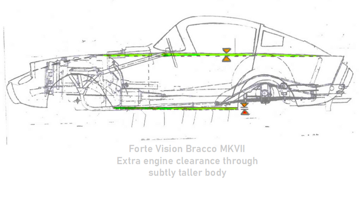
Comparing your adjusted 3D Model to my drawings….
WIDTH AND PLAN VIEW
Looking at the radius along the top of the wing line, from the tip of the headlamp cowling to the tip of the tail fin, the highlight (marked as a dark, purple dashed line, below) on the original photo' shows a transition from perhaps 4.25” - 4.5” radius (assuming a diameter of about 8.5 – 9 inches, based upon the 7” headlamp fitted to the Sevens), down to something closer to 1.5 - 2” radius from the bonnet shut-line and back to a point somewhere above the very end of the rear wheel-arch, after which the diameter again transitions to perhaps a 1” diameter at the tail light.
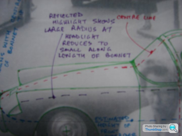

Assuming the windscreen is from an early Minx/Gazelle back window, and allowing for a fairly flat bridging curve down the body-sides adding perhaps another half inch each side, then the width of the body is somewhere around 54 inches, give or take a little.
On your model, also using the Minx windscreen and therefore having the same width out to the side-windows, the radius from the headlamp cowling is carried back along the top of the wing-line with a roughly unchanged radius, until a point somewhere above the rear wheel-arch, giving an overall width of about 59”. This doesn't seem to match the highlight in the original photo', giving the car a squatter, heavier and more modern appearance that what I am seeing in the photo'.
Below: My outline superimposed over _Sorted_s wider body (in grey tone). Note also the length of the roof extending beyond the rear wing tips on my outline view, and the longer, more rounded frontal treatment..
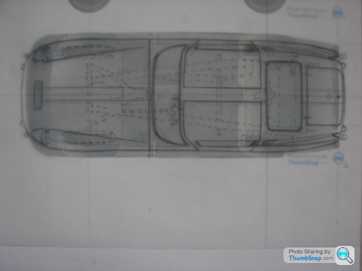

3-D model by _Sorted_
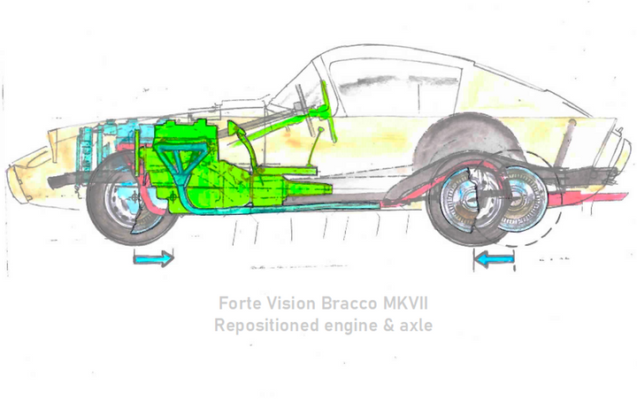
Drawing the red-dashed centreline onto the photo' (the white stripe is very helpful here) and extending to the nose, it is then fairly easy to draw a similar line, running parallel, up the bonnet from the outside-edge of the front overrider to see where is passes the headlamp cowling. I would estimate a gap of about 1.75 inches between the inside-edge of the cowling to the outside-edge of the overrider.
By drawing a line across the top of the overriders (below), it is clear that the very tip of the bonnet, on the centreline, is just fractionally behind this line (not clear on this image, as I'm using coloured pens for clarity, but they are a bit thick-nibbed).
[/url]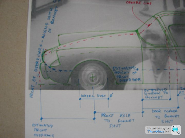
Another line, drawn by eye, running from front-centre of bonnet, under the headlamp indentation and back to the wheel-arch, gives a reasonably accurate idea of the height of the overrider relative to the wheel-arch, and the curve, in plan view, from the centre of the bonnet to the wheel-arch.
By then extending forward again, from this wheel-arch intersection, until it reaches the line already drawn across the top of the overriders, you get a reasonably accurate estimate of the front overhang.

By following these broad principles, combining an experienced eye, reading form from highlights and reflections, and by applying the principles of perspective and calculating ratios based on known (or at least, presumed in this case) dimensions, a good, reasonably accurate idea of size and form can be generated.
LENGTH & HEIGHT OF TAIL PANEL/ REAR WINGS

By extending lines across the tips of the rear fins, across the scuttle shut-line and across the top of the headlamp cowlings (the red lines above), exactly like the one across the front overriders already mentioned, and extending them upwards, they will meet at the perspective vanishing point. In this case, this falls at a point somewhere above the front edge of the front wheel. Extending the dashed-line downwards, toward us, the photographer/camera would be standing somewhere along this.
This results in a more direct, straight-on view of the front wing, with more perspective distortion toward the rear of the car. Where the rear wings appear to kink upwards behind the rear wheel-arch, I suspect they are, like _Sorted_ already said, in-fact tapered inwards in plan-view. It is even possible they may actually slope downward a little when viewed directly side-on.
Because the tip of the wing is further away (from the flat plane along the side of the car), and with the greater perspective effect at that side of the picture, it also appears slightly shorter on the image than it is in reality. The estimated rear overhang is therefore a little harder to assess than the front. Errors of this type can only really be assessed and corrected once a full 3-dimensional form (CAD model or real object) has been created and can be visually matched to photographs.

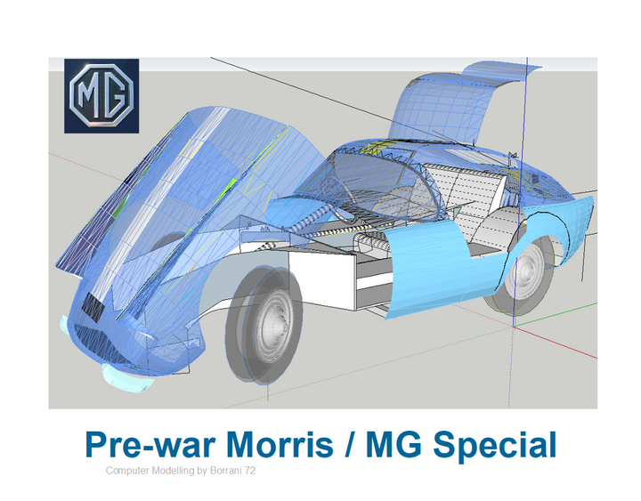
My outline compared to the Austin Big Seven

My outline compared with the 3-D model by _Sorted_
The main points of difference are the length of the nose, the length and height of the fastback roof/tail, the location of the boot handle (mine behind and below the level of the wing tips, _Sorted_s, sitting further forward and higher-up. Scuttle height; A-post also differ.
In plan view, my version is narrower based on the width of the Hillman sourced windscreen and the radius along the body-sides below the window-glass level. Corners have more tumblehome, and the overriders are closer together.

Model by _Sorted_ (adapted to fit Austin Big Seven)
Comparing the position of the boot handle (below) to the line across the rear wing tips, and again, drawing by eye the centre point of this line, an idea of the position of the handle can be ascertained.
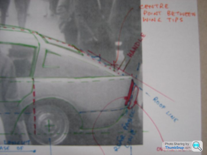
The clearance between the boot lid surface and the imaginary line looks to be something like 2”, which may be used to position the line of the sloping roof relative to the wing tips on the side-view of the scale drawing. It would also appear that the handle position is about 2” behind the imaginary line. This also ties-in with the position of the rear overriders (outlines in red, my note obscured in the corner), just visible in the shadows at the back of the car. The solid red area is, as far as I can make-out from the original image, the tail-light.
If this is the boot lid from an Austin Big Seven, then this ties in all the shut lines from that, and helps confirm the position of the rear window, which is what my scale drawings show, as I have assumed, in this case, that this is the base vehicle.

_Sorted_, you say that changing the body width throws-out the position of the fins, overriders, etc. I suspect this would be less of an issue if these points are repositioned as per my drawings, as you can now see more directly how the two models compare.
What would be most interesting, if you are willing, would be to put temporary markers, based upon my drawing, for these points into your model - for example, copy and paste the overriders into the new positions, put small spheres at the tips of the fins, etc.
This should allow the positions to be checked against the original image with minimal work.
I would be most keen to see the results.........
I didn't know that you could search Carfolio by all those criteria!
This is ideal for this approach, as it should give a manageable short-list of cars that could potentially fit the photo' proportions.
I'm not certain why none of the Ford 8 and 10s (7Y, E04A, Prefect etc) showed-up in your results?
Comparing your adjusted 3D Model to my drawings….
WIDTH AND PLAN VIEW
Looking at the radius along the top of the wing line, from the tip of the headlamp cowling to the tip of the tail fin, the highlight (marked as a dark, purple dashed line, below) on the original photo' shows a transition from perhaps 4.25” - 4.5” radius (assuming a diameter of about 8.5 – 9 inches, based upon the 7” headlamp fitted to the Sevens), down to something closer to 1.5 - 2” radius from the bonnet shut-line and back to a point somewhere above the very end of the rear wheel-arch, after which the diameter again transitions to perhaps a 1” diameter at the tail light.
Assuming the windscreen is from an early Minx/Gazelle back window, and allowing for a fairly flat bridging curve down the body-sides adding perhaps another half inch each side, then the width of the body is somewhere around 54 inches, give or take a little.
On your model, also using the Minx windscreen and therefore having the same width out to the side-windows, the radius from the headlamp cowling is carried back along the top of the wing-line with a roughly unchanged radius, until a point somewhere above the rear wheel-arch, giving an overall width of about 59”. This doesn't seem to match the highlight in the original photo', giving the car a squatter, heavier and more modern appearance that what I am seeing in the photo'.
Below: My outline superimposed over _Sorted_s wider body (in grey tone). Note also the length of the roof extending beyond the rear wing tips on my outline view, and the longer, more rounded frontal treatment..
3-D model by _Sorted_
Drawing the red-dashed centreline onto the photo' (the white stripe is very helpful here) and extending to the nose, it is then fairly easy to draw a similar line, running parallel, up the bonnet from the outside-edge of the front overrider to see where is passes the headlamp cowling. I would estimate a gap of about 1.75 inches between the inside-edge of the cowling to the outside-edge of the overrider.
By drawing a line across the top of the overriders (below), it is clear that the very tip of the bonnet, on the centreline, is just fractionally behind this line (not clear on this image, as I'm using coloured pens for clarity, but they are a bit thick-nibbed).
[/url]
Another line, drawn by eye, running from front-centre of bonnet, under the headlamp indentation and back to the wheel-arch, gives a reasonably accurate idea of the height of the overrider relative to the wheel-arch, and the curve, in plan view, from the centre of the bonnet to the wheel-arch.
By then extending forward again, from this wheel-arch intersection, until it reaches the line already drawn across the top of the overriders, you get a reasonably accurate estimate of the front overhang.
By following these broad principles, combining an experienced eye, reading form from highlights and reflections, and by applying the principles of perspective and calculating ratios based on known (or at least, presumed in this case) dimensions, a good, reasonably accurate idea of size and form can be generated.
LENGTH & HEIGHT OF TAIL PANEL/ REAR WINGS
By extending lines across the tips of the rear fins, across the scuttle shut-line and across the top of the headlamp cowlings (the red lines above), exactly like the one across the front overriders already mentioned, and extending them upwards, they will meet at the perspective vanishing point. In this case, this falls at a point somewhere above the front edge of the front wheel. Extending the dashed-line downwards, toward us, the photographer/camera would be standing somewhere along this.
This results in a more direct, straight-on view of the front wing, with more perspective distortion toward the rear of the car. Where the rear wings appear to kink upwards behind the rear wheel-arch, I suspect they are, like _Sorted_ already said, in-fact tapered inwards in plan-view. It is even possible they may actually slope downward a little when viewed directly side-on.
Because the tip of the wing is further away (from the flat plane along the side of the car), and with the greater perspective effect at that side of the picture, it also appears slightly shorter on the image than it is in reality. The estimated rear overhang is therefore a little harder to assess than the front. Errors of this type can only really be assessed and corrected once a full 3-dimensional form (CAD model or real object) has been created and can be visually matched to photographs.
My outline compared to the Austin Big Seven
My outline compared with the 3-D model by _Sorted_
The main points of difference are the length of the nose, the length and height of the fastback roof/tail, the location of the boot handle (mine behind and below the level of the wing tips, _Sorted_s, sitting further forward and higher-up. Scuttle height; A-post also differ.
In plan view, my version is narrower based on the width of the Hillman sourced windscreen and the radius along the body-sides below the window-glass level. Corners have more tumblehome, and the overriders are closer together.
Model by _Sorted_ (adapted to fit Austin Big Seven)
Comparing the position of the boot handle (below) to the line across the rear wing tips, and again, drawing by eye the centre point of this line, an idea of the position of the handle can be ascertained.
The clearance between the boot lid surface and the imaginary line looks to be something like 2”, which may be used to position the line of the sloping roof relative to the wing tips on the side-view of the scale drawing. It would also appear that the handle position is about 2” behind the imaginary line. This also ties-in with the position of the rear overriders (outlines in red, my note obscured in the corner), just visible in the shadows at the back of the car. The solid red area is, as far as I can make-out from the original image, the tail-light.
If this is the boot lid from an Austin Big Seven, then this ties in all the shut lines from that, and helps confirm the position of the rear window, which is what my scale drawings show, as I have assumed, in this case, that this is the base vehicle.
_Sorted_, you say that changing the body width throws-out the position of the fins, overriders, etc. I suspect this would be less of an issue if these points are repositioned as per my drawings, as you can now see more directly how the two models compare.
What would be most interesting, if you are willing, would be to put temporary markers, based upon my drawing, for these points into your model - for example, copy and paste the overriders into the new positions, put small spheres at the tips of the fins, etc.
This should allow the positions to be checked against the original image with minimal work.
I would be most keen to see the results.........

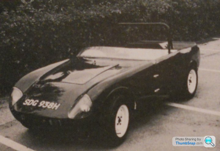
Hi Gareth1974, I looked at the Heron too. Pretty little cars.
Here are three, with an amazing variety of wheel diameters. The first two are almost certainly Austin Sevens (the Heron was designed for the 6'9" Seven chassis). Seven wheels got progressively smaller during their production run, so the black car is probably an early one.
The last one is anybodies guess (sadly, not registered with DVLA). 4-stud wheel hubs that look like they came from a spitfire maybe?

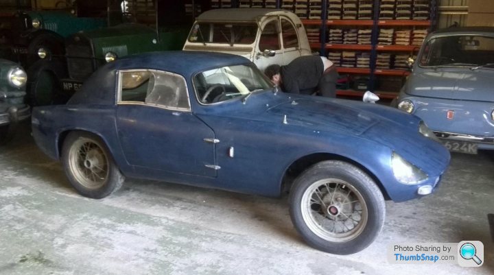
The drawing of the Heron was also a convenient basis for my own drawing - if Big Seven based, the mystery car is actually quite a lot larger than the tiny Heron.
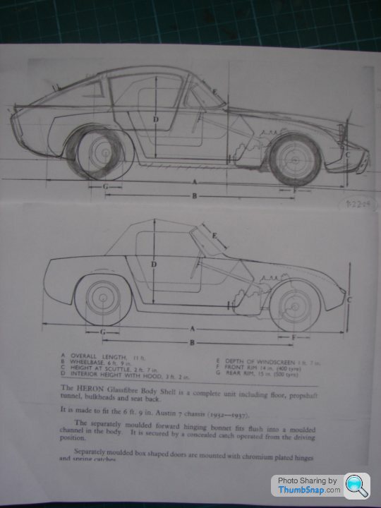
Please see page 127 for an explanation of these images:


Here are three, with an amazing variety of wheel diameters. The first two are almost certainly Austin Sevens (the Heron was designed for the 6'9" Seven chassis). Seven wheels got progressively smaller during their production run, so the black car is probably an early one.
The last one is anybodies guess (sadly, not registered with DVLA). 4-stud wheel hubs that look like they came from a spitfire maybe?
The drawing of the Heron was also a convenient basis for my own drawing - if Big Seven based, the mystery car is actually quite a lot larger than the tiny Heron.
Please see page 127 for an explanation of these images:
Edited by borrani72 on Monday 7th October 00:49
borrani72 said:
Your theory on the reducing wingtop roll is exactly what I was trying to suggest previously but could not articulate, and the whole car should be narrower and daintier, as you have pictured, than the CAD model. Looking forward to this developing further, I think this is the best stab yet.

Hi _Sorted_,
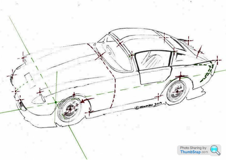
Below, data points as requested, plus some sketches to show visually their exact positions on the car. I have included the precise location of the wheel discs, which should make alignment to the image a little easier.
It will be interesting to see how accurately they will map onto the original photo'?
I think the estimated width is close to the real thing, although it could have been a fraction wider overall, I guess. I drew what felt right (on the scale drawings), interpreted from the radius visible in the photo', the apparent flatness of the body-sides and, to a lesser extent, the way the shape fitted the chassis. The windscreen width was created in the same way, effectively fitting these sides to the chassis, and agrees very closely with the one in your model, which I believe you 3-D scanned from the Minx rear window, so should be accurate.
I'm guessing the actual 'screen is close to 1260mm in overall width?
As to camera lens and position, other than the red, vertical line shown (in my previous post) in the perspective construction (where the camera would be located somewhere on that line), I have no way to calculate this graphically. It may be possible to reverse the “measured-plan” construction method, but I suspect distorting errors would creep in. In perspective constructions, and indeed, with my method for calculating relative sizes mathematically, the 'lens' is treated as a single point.
I suspect it could be done far more accurately using photogrammetric software. I'm not sure what sort of set-up you have, and whether you could attempt this by combining the original image with Austin Big Seven dimensions? I'm uncertain what more we could learn from this, rather than working from my 2-D views and matching them to the original image to assess accuracy and then tweaking the dimensions to improve the accuracy of the 2-D drawings. I would suggest that, should the model be a good match to the photo', it would then be possible to attempt placing the model within a 3-D-scanned Oxford Street to see the exact position.
I guess the main reason for this would be verification of the vehicle-size and proportions, as if all is correct, it should be possible to exactly fit the original image including the background?
SELECTED DATA POINTS
SCALE 1:1
DATUMS:
Centreline at ground level
Front Axle Line projected onto ground level
All dimensions in millimetres
Please refer to two attached perspective drawings for visual confirmation of point positions
(Sorry about the formatting - tabs don't work on the forums.........)
POINT - X- - Y - - Z -
Front wing tip -600 549 768
Nose tip -860 0 480
Overrider; Front - top centre – inside (body) edge -820 352 461
Overrider; Rear – top centre – inside (body) edge 3166 396 696
Body width (excluding wheel-arch flares):
Front arch TDC 0 689 634
Rear arch TDC 2210 689 634
Bonnet shut 758 ALL ALL
Windscreen base (outer edge of chrome trim) 775 0 895
Windscreen top (outer edge of chrome trim 1128 0 1229
Rear edge – roof panel 2179 0 1224
Point projected from side window top edge to A-post shut 1200 569 1174
Point projected from side window top to B-post shut 2083 559 1159
Boot handle mounting hole centre 3144 0 761
Extreme tip of rear fin 3120 528 864
Sill bottom corner – Front 367 648 247
Sill bottom corner – Rear 1848 648 247
Wheeldisc centrepoint – Front 0 607.5 307
Wheeldisc centrepoint – Rear 2210 631.5 307
Wheeldisc O/D 425

USING MEASURED PLAN PERSPECTIVE RENDERINGS....
To find the camera position with graphical methods would require doing all the below stages, but back-to-front, starting with the photo', projecting a perspective plan at ground level (where a lot of data would be missing), and finally reversing the perspective plan to an accurate 2-D plan view!
Working from a 2-D plan.....

....measurements are transferred graphically, building-up the perspective plan point-by-point.

Different 'viewpoint' heights may be selected to generate different views - low to high.........
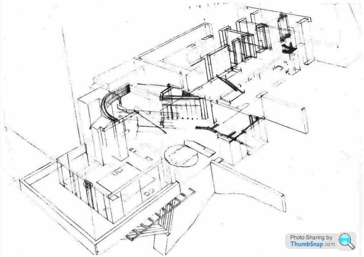
.......the above two views both derived from the same perspective plan.
This view is a cutaway, so the roof has been ignored. This roof information, and any hidden details, not being in the final image, could not then be used to reverse the process and reconstruct the original floor plan. For exactly this reason, applying the process to the mystery car picture would result in a large amount of 'missing' information. The position of the far wheels, the alignment of the steering column and much more.........
A new perspective plan (not shown in full) was used for a different viewpoint.

A partial perspective plan (added for construction of railings and other details), shows how each point on the finished view is directly above the equivalent point on the perspective plan.
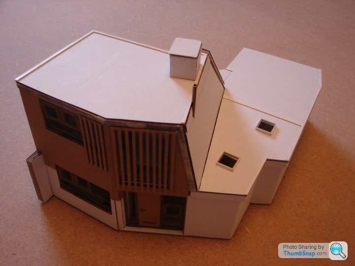
As for card buildings, here's own I designed earlier....


Below, data points as requested, plus some sketches to show visually their exact positions on the car. I have included the precise location of the wheel discs, which should make alignment to the image a little easier.
It will be interesting to see how accurately they will map onto the original photo'?
I think the estimated width is close to the real thing, although it could have been a fraction wider overall, I guess. I drew what felt right (on the scale drawings), interpreted from the radius visible in the photo', the apparent flatness of the body-sides and, to a lesser extent, the way the shape fitted the chassis. The windscreen width was created in the same way, effectively fitting these sides to the chassis, and agrees very closely with the one in your model, which I believe you 3-D scanned from the Minx rear window, so should be accurate.
I'm guessing the actual 'screen is close to 1260mm in overall width?
As to camera lens and position, other than the red, vertical line shown (in my previous post) in the perspective construction (where the camera would be located somewhere on that line), I have no way to calculate this graphically. It may be possible to reverse the “measured-plan” construction method, but I suspect distorting errors would creep in. In perspective constructions, and indeed, with my method for calculating relative sizes mathematically, the 'lens' is treated as a single point.
I suspect it could be done far more accurately using photogrammetric software. I'm not sure what sort of set-up you have, and whether you could attempt this by combining the original image with Austin Big Seven dimensions? I'm uncertain what more we could learn from this, rather than working from my 2-D views and matching them to the original image to assess accuracy and then tweaking the dimensions to improve the accuracy of the 2-D drawings. I would suggest that, should the model be a good match to the photo', it would then be possible to attempt placing the model within a 3-D-scanned Oxford Street to see the exact position.
I guess the main reason for this would be verification of the vehicle-size and proportions, as if all is correct, it should be possible to exactly fit the original image including the background?
SELECTED DATA POINTS
SCALE 1:1
DATUMS:
Centreline at ground level
Front Axle Line projected onto ground level
All dimensions in millimetres
Please refer to two attached perspective drawings for visual confirmation of point positions
(Sorry about the formatting - tabs don't work on the forums.........)
POINT - X- - Y - - Z -
Front wing tip -600 549 768
Nose tip -860 0 480
Overrider; Front - top centre – inside (body) edge -820 352 461
Overrider; Rear – top centre – inside (body) edge 3166 396 696
Body width (excluding wheel-arch flares):
Front arch TDC 0 689 634
Rear arch TDC 2210 689 634
Bonnet shut 758 ALL ALL
Windscreen base (outer edge of chrome trim) 775 0 895
Windscreen top (outer edge of chrome trim 1128 0 1229
Rear edge – roof panel 2179 0 1224
Point projected from side window top edge to A-post shut 1200 569 1174
Point projected from side window top to B-post shut 2083 559 1159
Boot handle mounting hole centre 3144 0 761
Extreme tip of rear fin 3120 528 864
Sill bottom corner – Front 367 648 247
Sill bottom corner – Rear 1848 648 247
Wheeldisc centrepoint – Front 0 607.5 307
Wheeldisc centrepoint – Rear 2210 631.5 307
Wheeldisc O/D 425
USING MEASURED PLAN PERSPECTIVE RENDERINGS....
To find the camera position with graphical methods would require doing all the below stages, but back-to-front, starting with the photo', projecting a perspective plan at ground level (where a lot of data would be missing), and finally reversing the perspective plan to an accurate 2-D plan view!
Working from a 2-D plan.....
....measurements are transferred graphically, building-up the perspective plan point-by-point.
Different 'viewpoint' heights may be selected to generate different views - low to high.........
.......the above two views both derived from the same perspective plan.
This view is a cutaway, so the roof has been ignored. This roof information, and any hidden details, not being in the final image, could not then be used to reverse the process and reconstruct the original floor plan. For exactly this reason, applying the process to the mystery car picture would result in a large amount of 'missing' information. The position of the far wheels, the alignment of the steering column and much more.........
A new perspective plan (not shown in full) was used for a different viewpoint.
A partial perspective plan (added for construction of railings and other details), shows how each point on the finished view is directly above the equivalent point on the perspective plan.
As for card buildings, here's own I designed earlier....
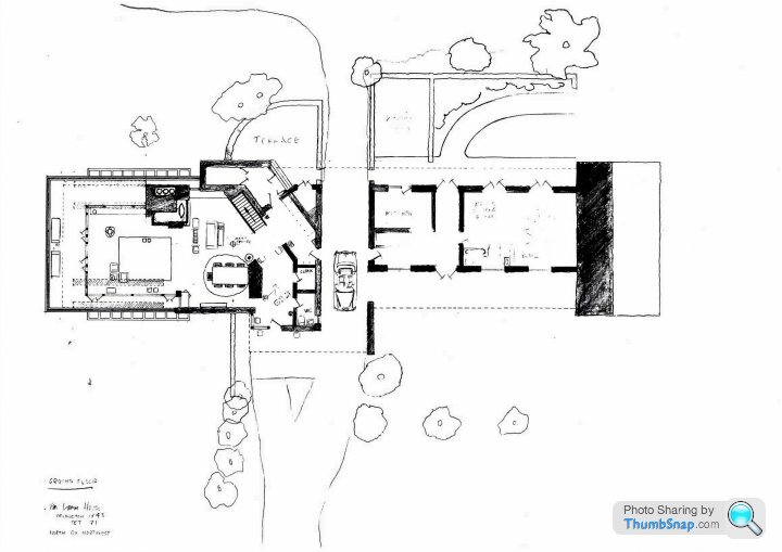
Well spotted swisstoni,
it's the Vandamm House from 'North by Northwest', 1959, directed by Alfred Hitchcock.
The house was designed, in the style of American architect Frank LLoyd Wright, by Hitchcocks' art department. Sadly only one end of it ever existed, and then only as a film set. The design was never fully completed and the set didn't entirely match the two matte shots (background paintings) of the exteriors.
Here's a brief introduction to anybody interested.....
https://www.productiondesignerscollective.org/sing...
Please see page 127 for an explanation of these images:
Edited by borrani72 on Monday 7th October 00:52
Gassing Station | Classic Cars and Yesterday's Heroes | Top of Page | What's New | My Stuff