Mac#1 Motorsport Worx Build
Discussion


Been buying a few winter upgrades, here we have one dry sump
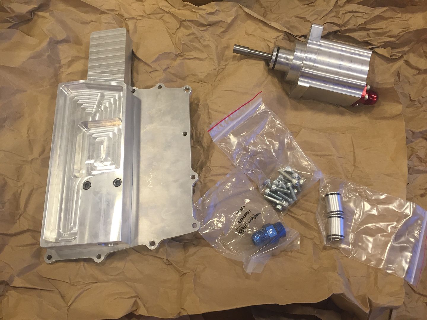
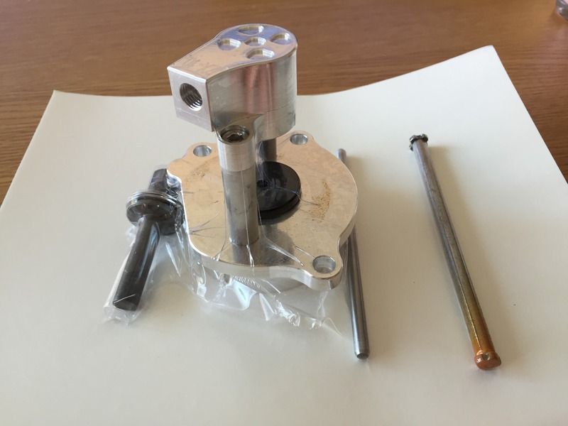
The twin stage scavenge pump
The scavenge pump fits in place of the standard water pump
The oil pump shaft has a slotted coupling to mate with the oil pump shaft, it is then driven in the same way the original water pump would be.
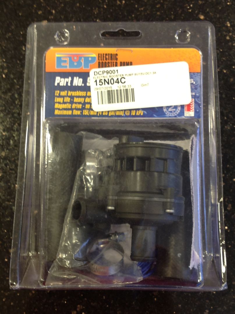
As the standard water pump will be removed, an electric water pump is required, so a Davies Craig unit was bought. The electric pump will be nice as it'll be able to run on via thermostat control after stopping the engine to allow the engine/coolant to be cooled down thoroughly.
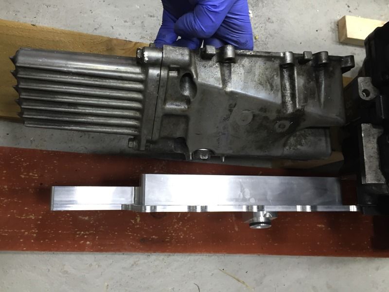
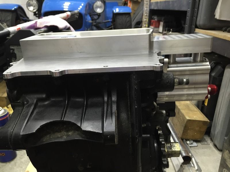
Standard sump removed from my spare engine and compared with the shallow dry sump pan
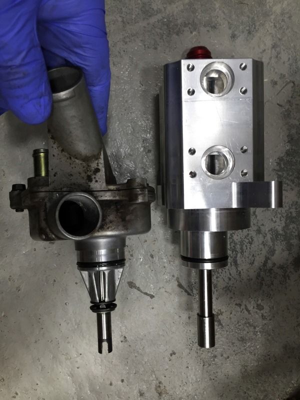
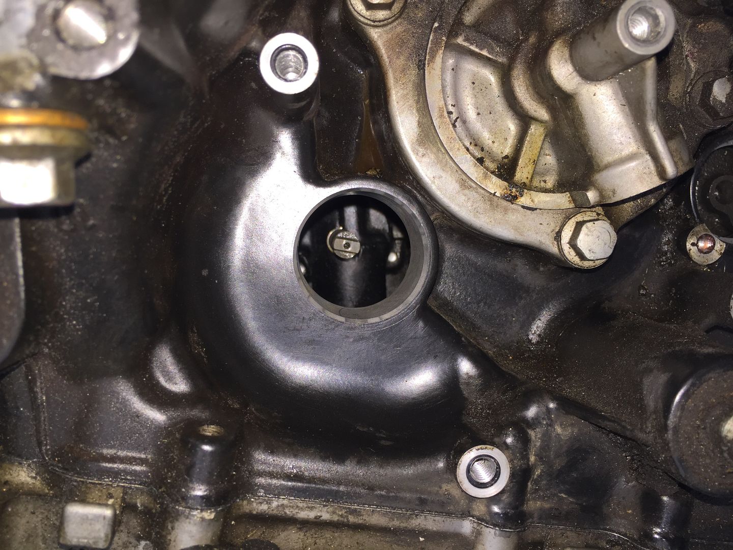
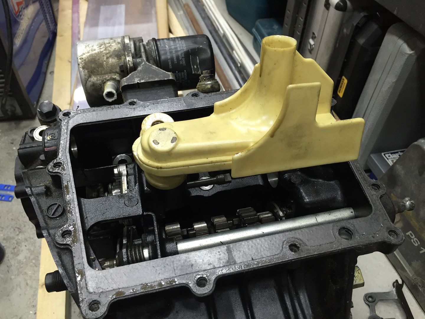
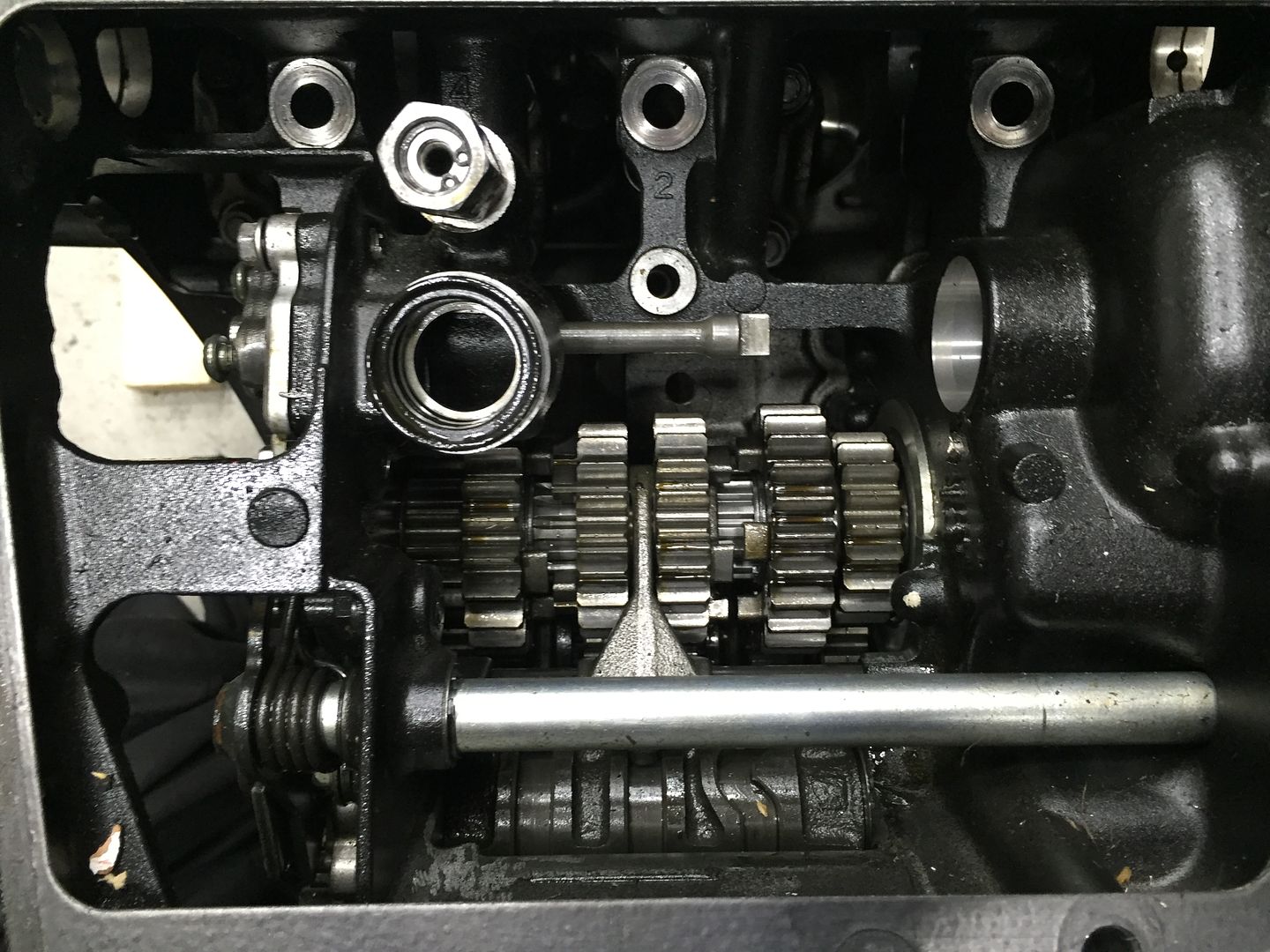
Standard Kawasaki oil pickup arrangement
Oil pickup removed, you can see the oil pump shaft with the flats on the right hand side of it which will drive the oil scavenge pump and just to the left of centre the oil port that supplies the standard oil pump with oil.
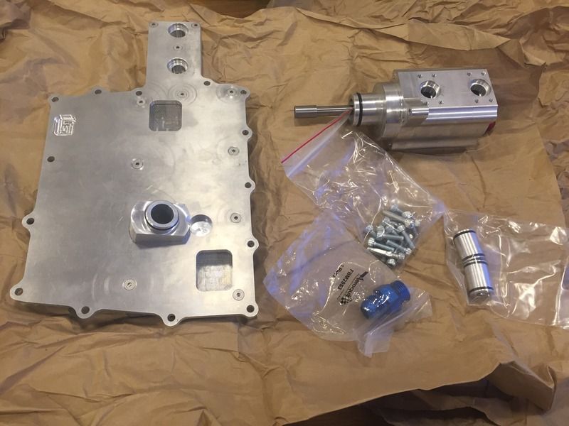
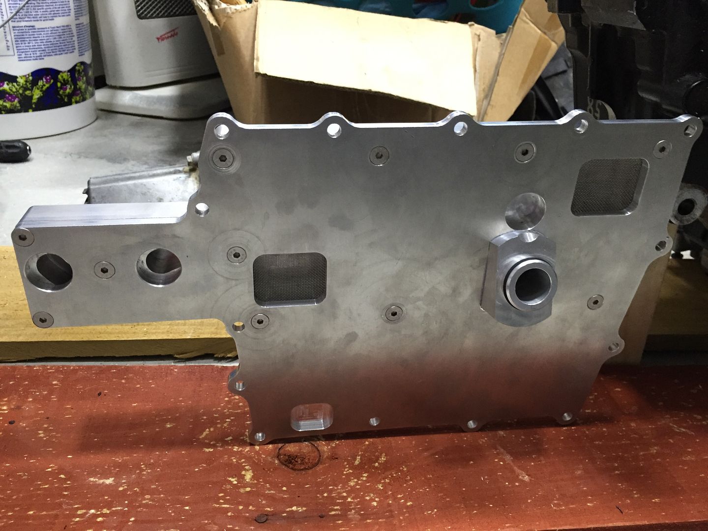
This is the inside of the dry sump pan.
The two meshed cutouts are connected to the two round ports at the left side, this is where the oil is pulled from the sump/crankcase by the oil scavenge pump.
The round port in the centre is where the oil is fed to the standard engine oil pump, it is connected to a threaded inlet which is not visible at the right side of this photo, this threaded inlet is connected via a hose to the baffled oil storage reservoir tank.
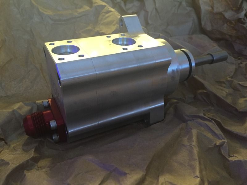
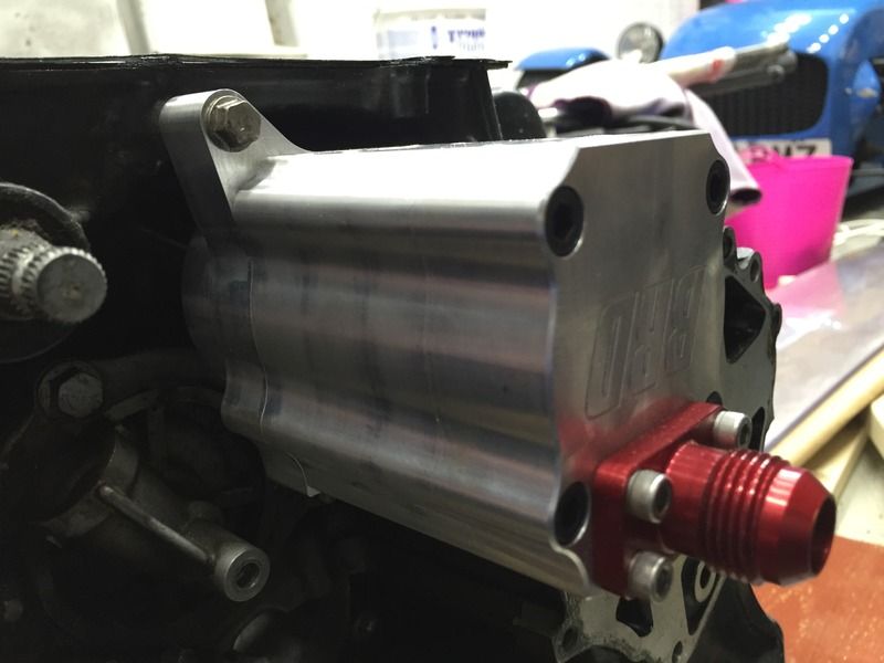
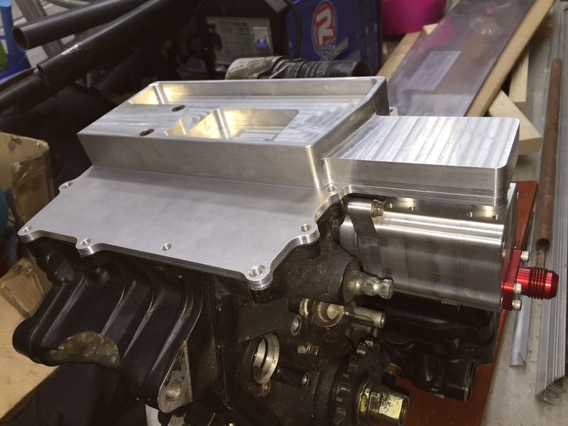
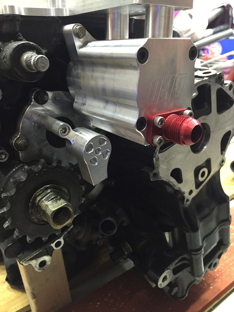
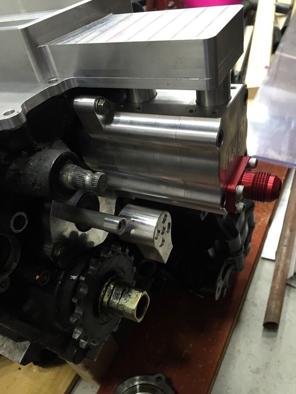
Here the scavenge pump is installed to the engine. The red fitting at the right side is the pump outlet, this will return the engine oil to the oil storage reservoir, possibly via thermostat/oil cooler to remove some load from the original engine oil pump.
Two o-ringed tubes are installed into the scavenge pump inlet ports
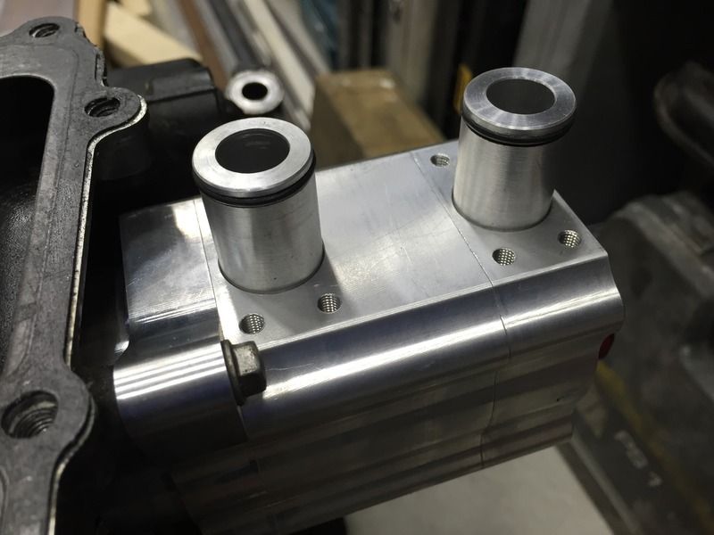
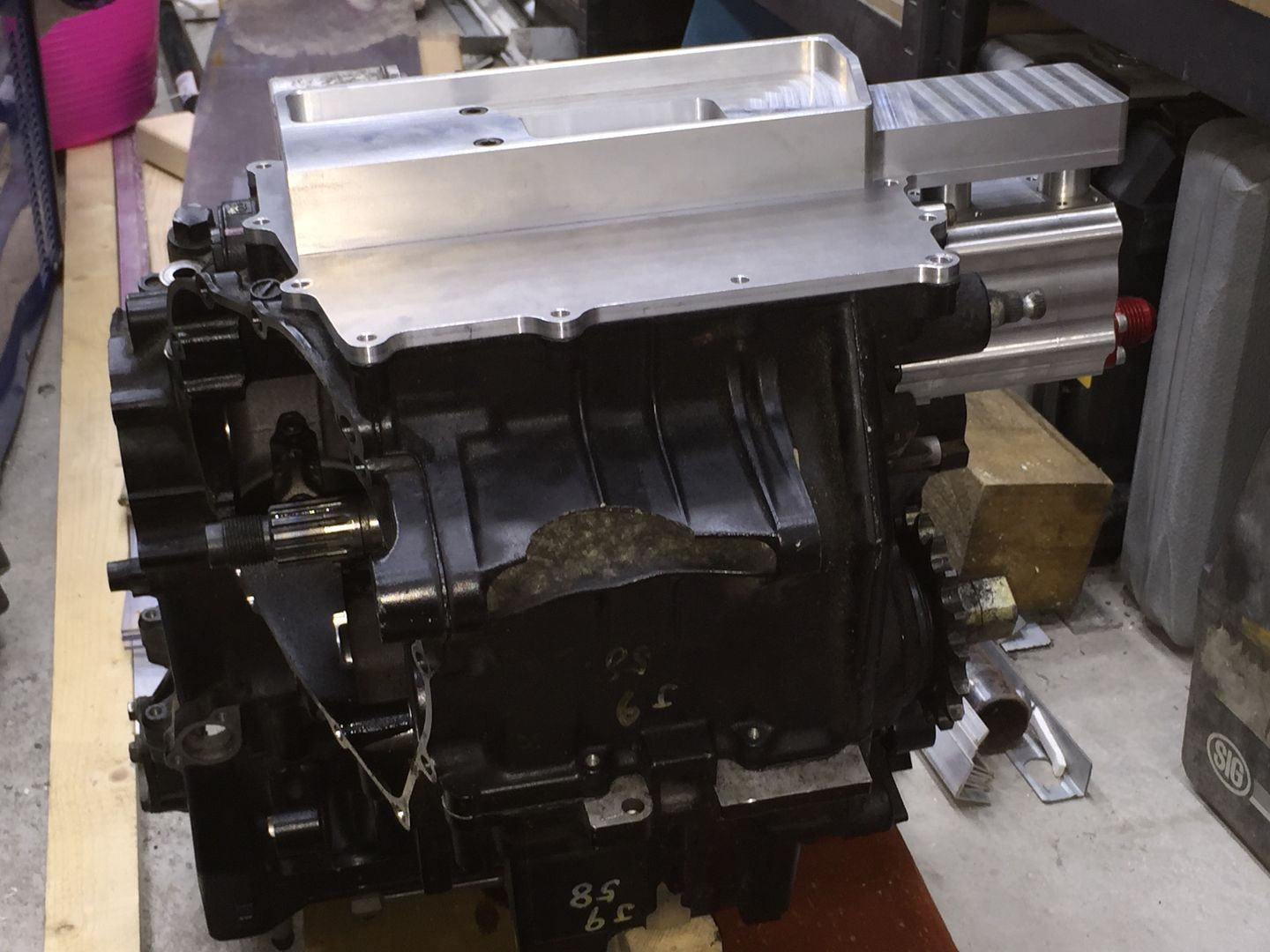
Sump installed to the engine, you can see how the two o-ringed tubes connect the sump to the oil pump very neatly.


The twin stage scavenge pump

The scavenge pump fits in place of the standard water pump

The oil pump shaft has a slotted coupling to mate with the oil pump shaft, it is then driven in the same way the original water pump would be.

As the standard water pump will be removed, an electric water pump is required, so a Davies Craig unit was bought. The electric pump will be nice as it'll be able to run on via thermostat control after stopping the engine to allow the engine/coolant to be cooled down thoroughly.

Standard sump removed from my spare engine and compared with the shallow dry sump pan

Standard Kawasaki oil pickup arrangement

Oil pickup removed, you can see the oil pump shaft with the flats on the right hand side of it which will drive the oil scavenge pump and just to the left of centre the oil port that supplies the standard oil pump with oil.

This is the inside of the dry sump pan.
The two meshed cutouts are connected to the two round ports at the left side, this is where the oil is pulled from the sump/crankcase by the oil scavenge pump.
The round port in the centre is where the oil is fed to the standard engine oil pump, it is connected to a threaded inlet which is not visible at the right side of this photo, this threaded inlet is connected via a hose to the baffled oil storage reservoir tank.

Here the scavenge pump is installed to the engine. The red fitting at the right side is the pump outlet, this will return the engine oil to the oil storage reservoir, possibly via thermostat/oil cooler to remove some load from the original engine oil pump.

Two o-ringed tubes are installed into the scavenge pump inlet ports

Sump installed to the engine, you can see how the two o-ringed tubes connect the sump to the oil pump very neatly.


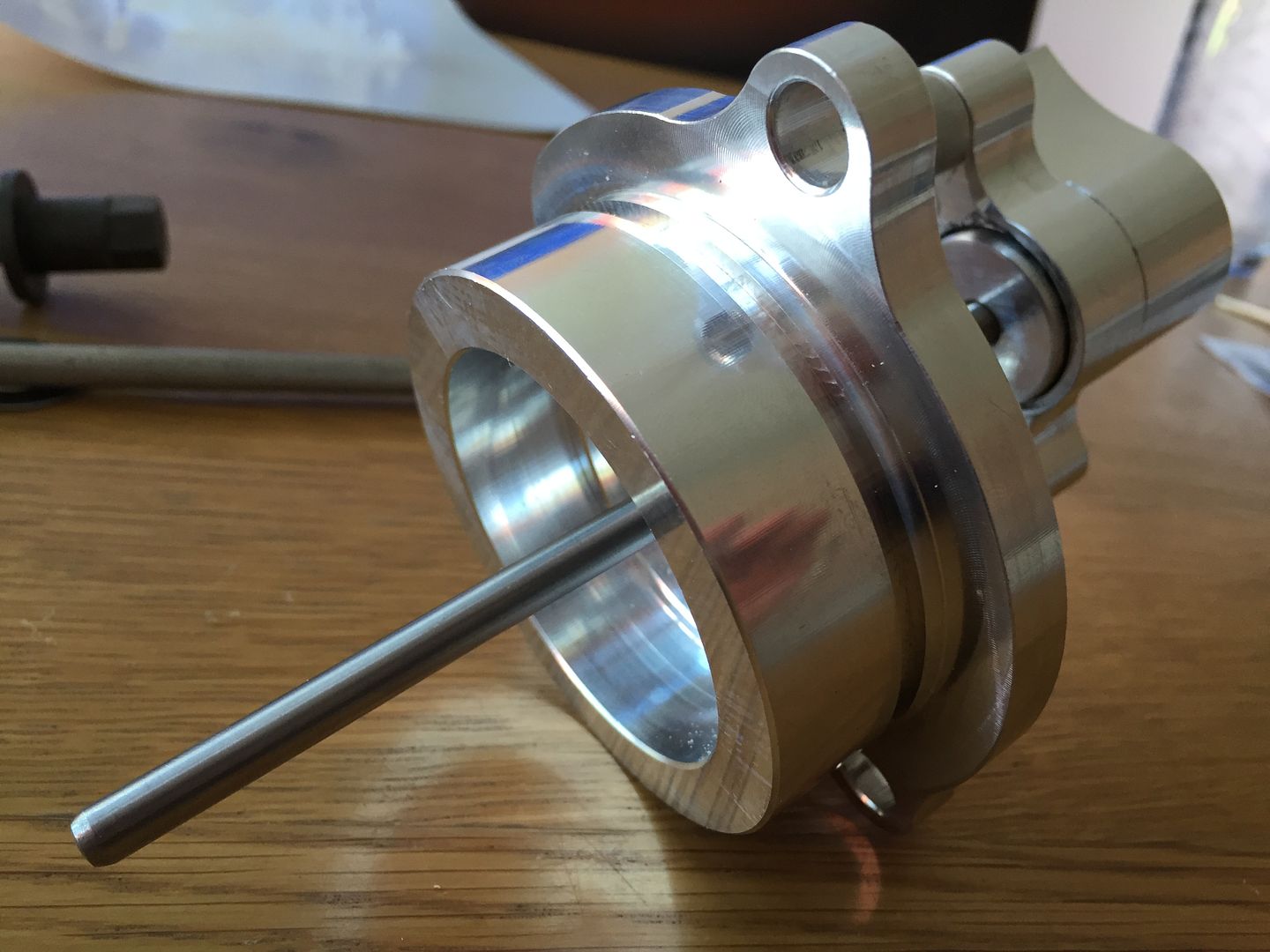
Hydraulic clutch slave cylinder assembly.
The original Kawasaki uses a cable which pulls on a lever, this lever pulls on a pin in the centre of the clutch which opens a gap between the clutch plates, thereby disengaging the clutch.
The hydraulic slave cylinder is mounted to the opposite side of the engine to the clutch assembly, as the transmission input shaft that the clutch is mounted on is hollow, this means that hydraulic slave cylinder can push a rod through the centre of the input shaft and disengage the clutch.
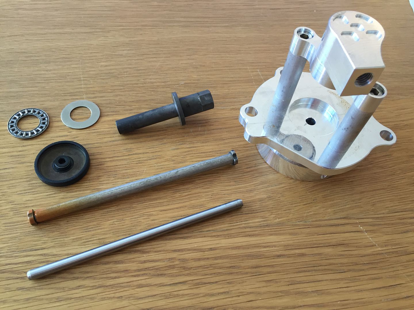
Oil seal, only posted here for my future reference
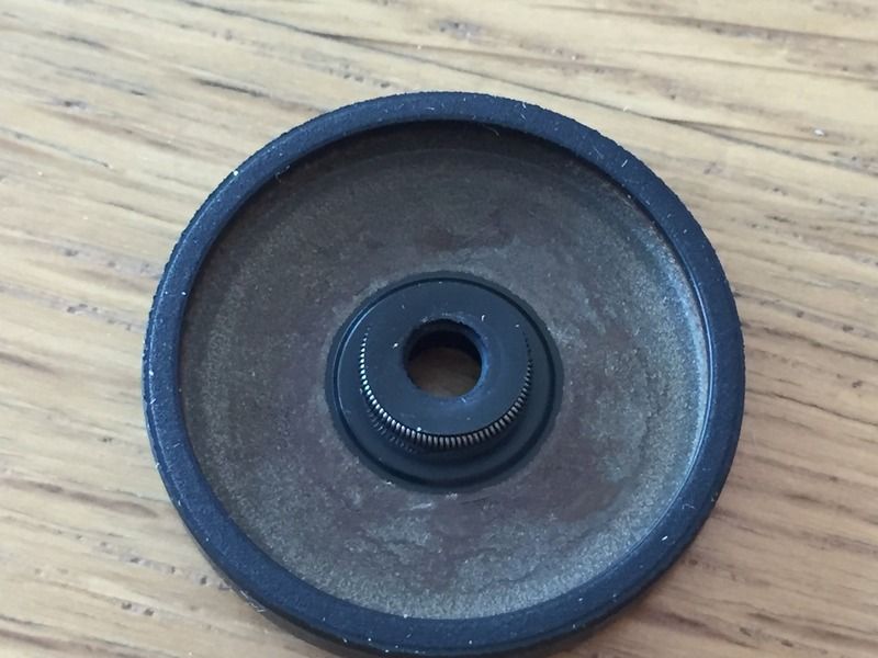
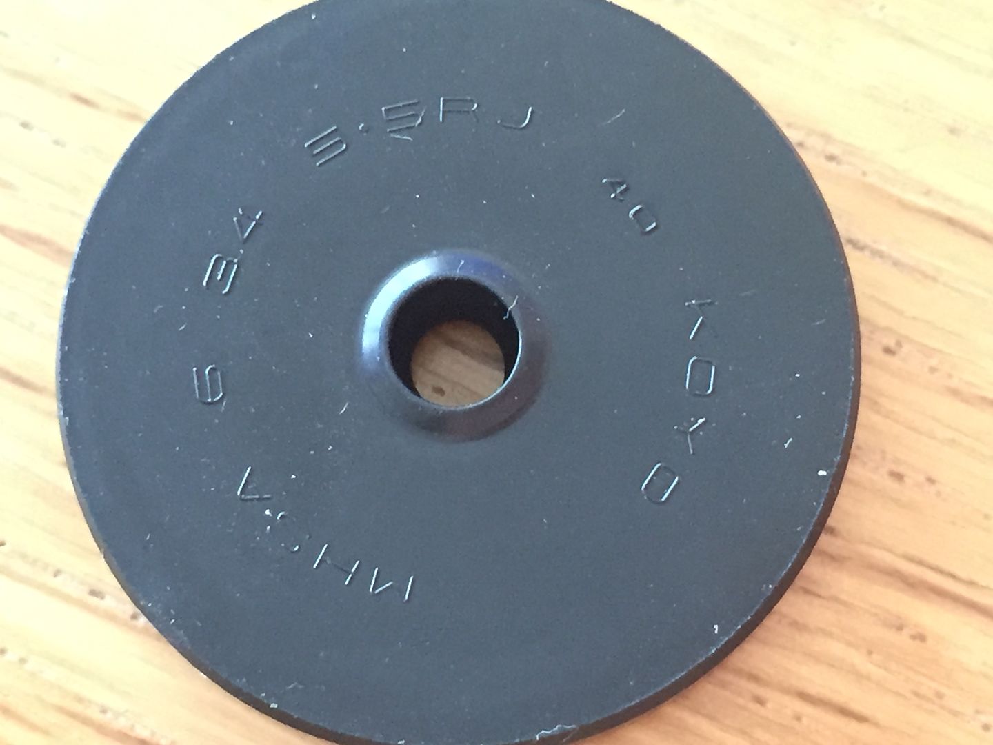
Seal and push rod installed.
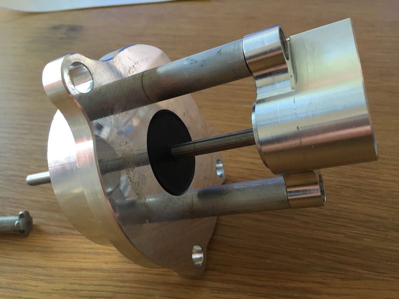
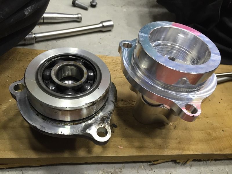
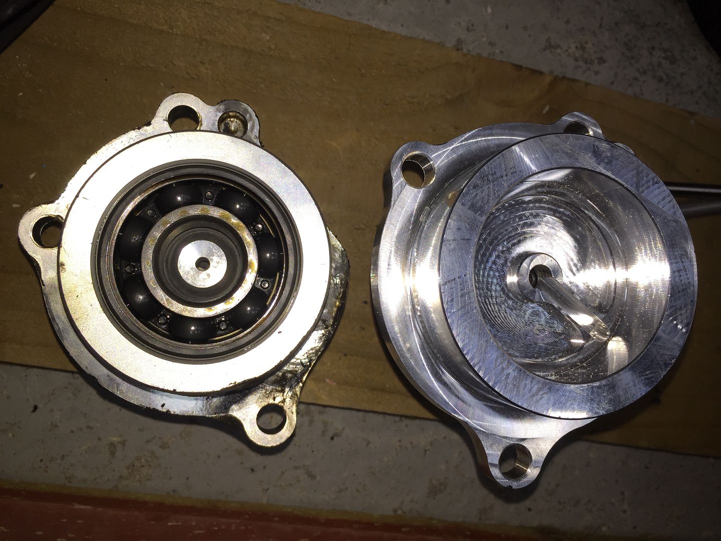
The slave cylinder assembly is designed to replace the input shaft end bearing housing, so a new bearing will need to be installed into it prior to final installation. You can see the machined oilway in the bottom of the bearing housing which feeds oil from the engine casing to the bearing.
Clutch slave cylinder assembly installed on the engine, adequate clearance noted between the dry sump oil scavenge pump and sprocket, or in my case on the car, the sprocket adaptor which mates to the propshaft.
The original Kawasaki uses a cable which pulls on a lever, this lever pulls on a pin in the centre of the clutch which opens a gap between the clutch plates, thereby disengaging the clutch.
The hydraulic slave cylinder is mounted to the opposite side of the engine to the clutch assembly, as the transmission input shaft that the clutch is mounted on is hollow, this means that hydraulic slave cylinder can push a rod through the centre of the input shaft and disengage the clutch.


Oil seal, only posted here for my future reference
Seal and push rod installed.

The slave cylinder assembly is designed to replace the input shaft end bearing housing, so a new bearing will need to be installed into it prior to final installation. You can see the machined oilway in the bottom of the bearing housing which feeds oil from the engine casing to the bearing.


Clutch slave cylinder assembly installed on the engine, adequate clearance noted between the dry sump oil scavenge pump and sprocket, or in my case on the car, the sprocket adaptor which mates to the propshaft.


jontysafe said:
Please for the love of GOD do NOT USE THAT PUMP as main coolant pump.
You WILL kill your engine
http://www.sbdev.co.uk/Hayabusa/Hayabusa_cooling_systems.htmYou WILL kill your engine
I couldn't find a flow output rating for the standard bike water pump for direct comparison, but that's not the case according to SBD Motorsport.
Other people in America have ran similar pumps on bikes with no issues
Easily upgraded to a larger pump if required.
Still I wouldn't put one of those near my car. I had that exact pump as my intercooler pump.
If using an electric pump was as good or as easy as that then all the OEMs would be doing it. BMW, Merc and VW are now but look at what they are using. The small Bosch or Davies Craig thingies are woefully under spec.
Look at:
Pierburg cwa200 and 400 with a CAN controller like this: http://www.tecomotive.com/en/tinycwa-en
This is what I will be using. If you want to go smaller then they do a cwa50 and cwa100.
Speak to Max Power on here.
Edited by jontysafe on Saturday 3rd September 23:31
Red16 said:
http://www.sbdev.co.uk/Hayabusa/Hayabusa_cooling_s...
I couldn't find a flow output rating for the standard bike water pump for direct comparison, but that's not the case according to SBD Motorsport.
Other people in America have ran similar pumps on bikes with no issues
Easily upgraded to a larger pump if required.
It's not necessarily flow but head. Show those pumps any pressure and flow dies. Even their bigger pumps flow sweet FA at typical coolant system pressure.I couldn't find a flow output rating for the standard bike water pump for direct comparison, but that's not the case according to SBD Motorsport.
Other people in America have ran similar pumps on bikes with no issues
Easily upgraded to a larger pump if required.
Plenty time over the winter to consider my options on water flow, i'll give it some further thought.
Slighty different issue but flow related all the same, the oil pump and oil pressure. Low hot idle pressure is an issue on a lot of high performance bikes and bike engines, currently my oil pressure is great when cold but once hot and at low rpm it drops away to very low figures, increasing the engine idle speed gets around the issue but that's a crude and frankly annoying remedy.
This low pressure could be due to excessive leakage past the main and big end bearings, but the engine was rebuilt fairly recently and the car has not done a lot of miles, so i'm pretty confident those clearances are still ok. It could also be that the standard oil pump feeding thermostatic plate, external oil cooler, turbo and all the external hoses is asking a bit too much. Or any one of a host of other resons.
Other bike engines such as the ZX12R, ZX14R, Hayabusa, GSXR1000 have overdrive oil pump gears available off the shelf from tuning companies, these gears typically overdrive the oil pump by around 10%, but unfortunately my ZX10R does not have this luxury, so it's down to the DIY approach once again.
Here's the standard oil pump and drive gear arrangement
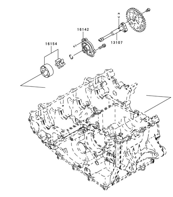
The oil pump gear is driven by the flywheel, which is driven by the crankshaft. Here are the gears on the flywheel and oil pump.
The standard drive ratio is 31 teeth on the flywheel which drives the oil pumps 37 teeth, 31:37 or 1.194:1.
By measuring the original gears and shaft centre distances, I've found gears that will allow me to change from 31:37 to 33:35 and will mesh correctly at my shaft centre distance. This new gear ratio will increase oil pump rotation speed by 12.5%, meaning i can reduce idle speed to normal and still have good oil pressure at hot idle, which is great as i plan some oiling modifications which will be detailed later in the thread.
Here is the clutch basket, you can see the three rivots which hold the flywheel and basket assembly together.
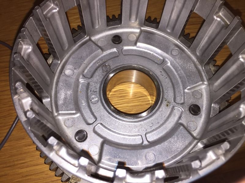
With the assembly viewed from the other side you can see the rivots and the drive gear that is part of the flywheel, this needs to be removed.
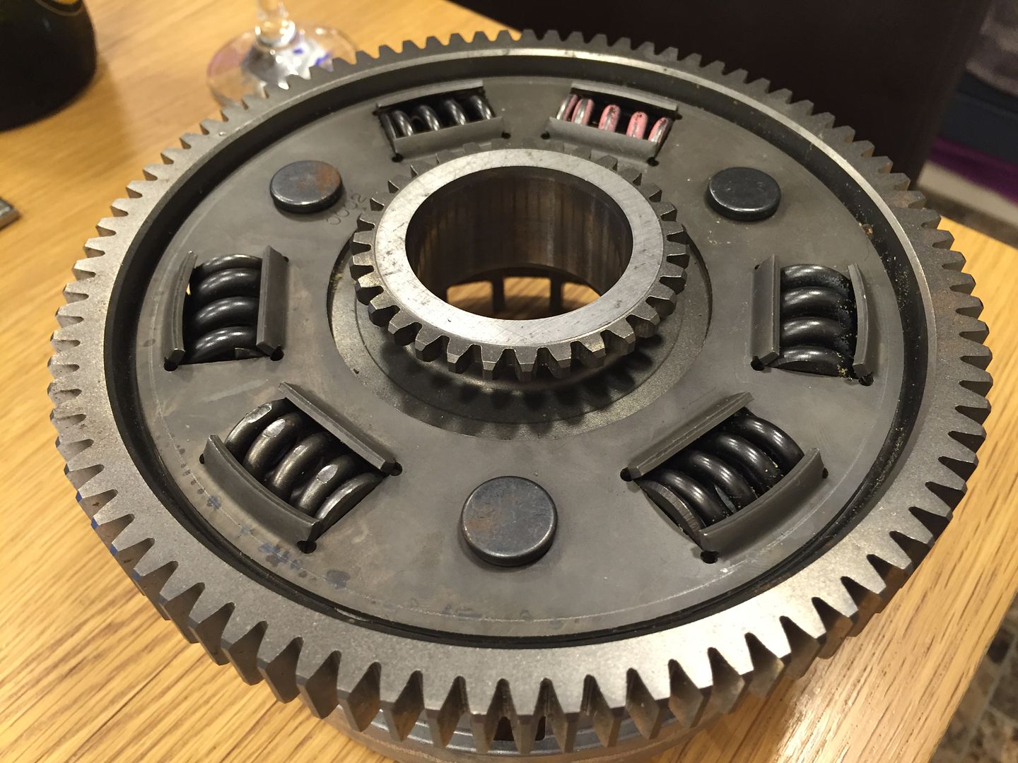
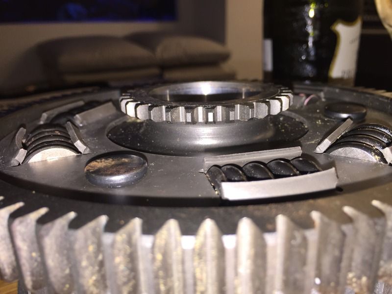
With the three rivots removed the clutch assembly looks like this
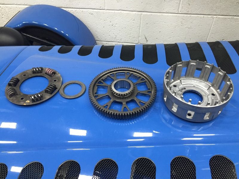
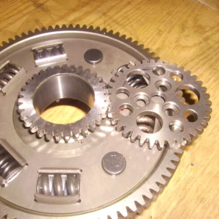
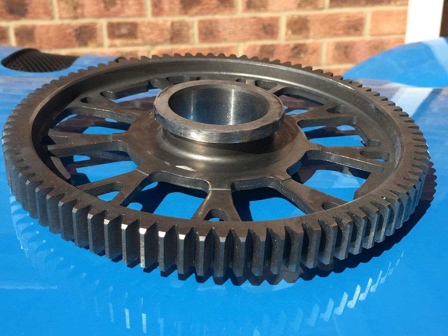
Flywheel, driven by the crankshaft on the big outer, drives the oil pump on the small teeth
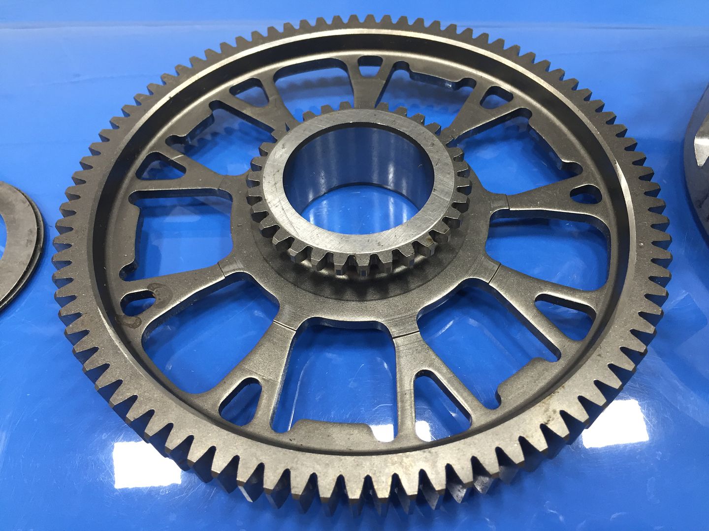
Oil pump drive gear teeth ground off, the flywheel is now away being machined to remove the rest of the small gear and have a light skim on the outer diameter where the oil pump drive gear gear currently is.
Once the flywheel is finished being machined it can be measured up and a gear sleeve like this can be made up to match the new gear ratio. This gear sleeve will be an interference fit on the flywheel so it will need to be heated up and shrunk onto the flywheel. Not decided wether to TIG weld and skim it again once it's shrunk on yet.
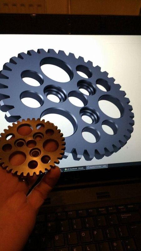
A friend is pretty handy with CAD and 3D modelling, here's the gear that fits on the oil pump shaft being modelled, once the above is done i'll need this gear remade with the correct dimension and teeth to suit the flywheel.
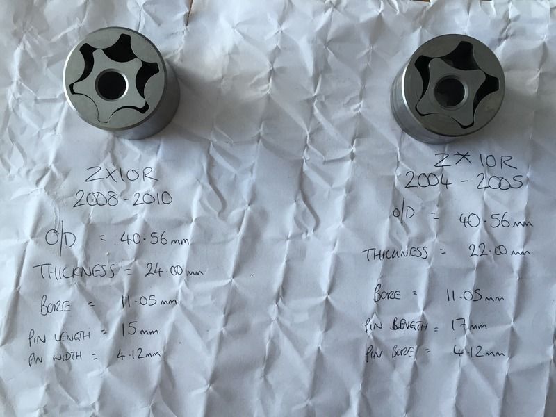
One other thing that needs a bit of research is the oil pump assembly. The later model 2008-2010 pump is 2mm (approx 10%) longer than my pump and it's drive ratio is also different, it is in fact driven more slowly, possibly because it outputs more oil per revolution than mine does with it being different number of teeth and length. There is enough material in my engine casing to allow my oil pump housing to be machined to allow the newer pump to fit... more reading and thinking required!
Slighty different issue but flow related all the same, the oil pump and oil pressure. Low hot idle pressure is an issue on a lot of high performance bikes and bike engines, currently my oil pressure is great when cold but once hot and at low rpm it drops away to very low figures, increasing the engine idle speed gets around the issue but that's a crude and frankly annoying remedy.
This low pressure could be due to excessive leakage past the main and big end bearings, but the engine was rebuilt fairly recently and the car has not done a lot of miles, so i'm pretty confident those clearances are still ok. It could also be that the standard oil pump feeding thermostatic plate, external oil cooler, turbo and all the external hoses is asking a bit too much. Or any one of a host of other resons.
Other bike engines such as the ZX12R, ZX14R, Hayabusa, GSXR1000 have overdrive oil pump gears available off the shelf from tuning companies, these gears typically overdrive the oil pump by around 10%, but unfortunately my ZX10R does not have this luxury, so it's down to the DIY approach once again.
Here's the standard oil pump and drive gear arrangement

The oil pump gear is driven by the flywheel, which is driven by the crankshaft. Here are the gears on the flywheel and oil pump.

The standard drive ratio is 31 teeth on the flywheel which drives the oil pumps 37 teeth, 31:37 or 1.194:1.
By measuring the original gears and shaft centre distances, I've found gears that will allow me to change from 31:37 to 33:35 and will mesh correctly at my shaft centre distance. This new gear ratio will increase oil pump rotation speed by 12.5%, meaning i can reduce idle speed to normal and still have good oil pressure at hot idle, which is great as i plan some oiling modifications which will be detailed later in the thread.
Here is the clutch basket, you can see the three rivots which hold the flywheel and basket assembly together.

With the assembly viewed from the other side you can see the rivots and the drive gear that is part of the flywheel, this needs to be removed.


With the three rivots removed the clutch assembly looks like this

Flywheel, driven by the crankshaft on the big outer, drives the oil pump on the small teeth

Oil pump drive gear teeth ground off, the flywheel is now away being machined to remove the rest of the small gear and have a light skim on the outer diameter where the oil pump drive gear gear currently is.

Once the flywheel is finished being machined it can be measured up and a gear sleeve like this can be made up to match the new gear ratio. This gear sleeve will be an interference fit on the flywheel so it will need to be heated up and shrunk onto the flywheel. Not decided wether to TIG weld and skim it again once it's shrunk on yet.
A friend is pretty handy with CAD and 3D modelling, here's the gear that fits on the oil pump shaft being modelled, once the above is done i'll need this gear remade with the correct dimension and teeth to suit the flywheel.

One other thing that needs a bit of research is the oil pump assembly. The later model 2008-2010 pump is 2mm (approx 10%) longer than my pump and it's drive ratio is also different, it is in fact driven more slowly, possibly because it outputs more oil per revolution than mine does with it being different number of teeth and length. There is enough material in my engine casing to allow my oil pump housing to be machined to allow the newer pump to fit... more reading and thinking required!

jontysafe said:
Why can't you just add a pressure stage to your dry sump system?
I could do it that way but I plan to build a turbo motorbike after this car is finished, bike will be the donor bike my engine is from and running a wet sump so will use the exact same parts as my car regarding oil pump overdrive gear setup etc.

Coskev said:
Some nice parts there 
Is the clutch a fully custom design?
Both the lock up clutch and hydraulic clutch pusher are off the shelf upgrades from companies in America.Is the clutch a fully custom design?
Coskev said:
How's this looking now?
Long time since a update again!
Do you run a vented 'drip tank' on your turbo oil return,then the scavenge pump pulls out of the tank?
No real change with the car at the moment, but that's about to start happening, the engine is out and upgrades are in progress, i'll detail them soon.Long time since a update again!
Do you run a vented 'drip tank' on your turbo oil return,then the scavenge pump pulls out of the tank?
I used to run a hose with JIC fittings from the turbo oil drain to the electric scavenge pump then a hose with JIC4 fittings from the scavenge pump to the clutch cover, where it returned to the crankcase via the oil filler hole. The electric scavenge pump is now gone and the turbo will drain back to the crankcase via a custom insert in the oil level sight glass location.
Mr MXT said:
Enjoyed reading this, any updates OP?
I'm about to start the updates now.New goodies bought but not installed...
One Davis Craig EWP80 water pump with MBE amplifier to allow the ECU to control the speed (output) of the pump depending on temperature.
There is also an oil temperature sensor in there too, which will be installed into the dry sump oil tank.
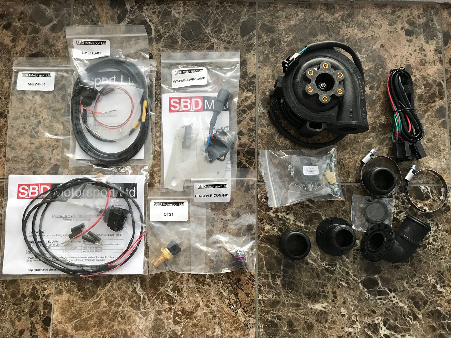
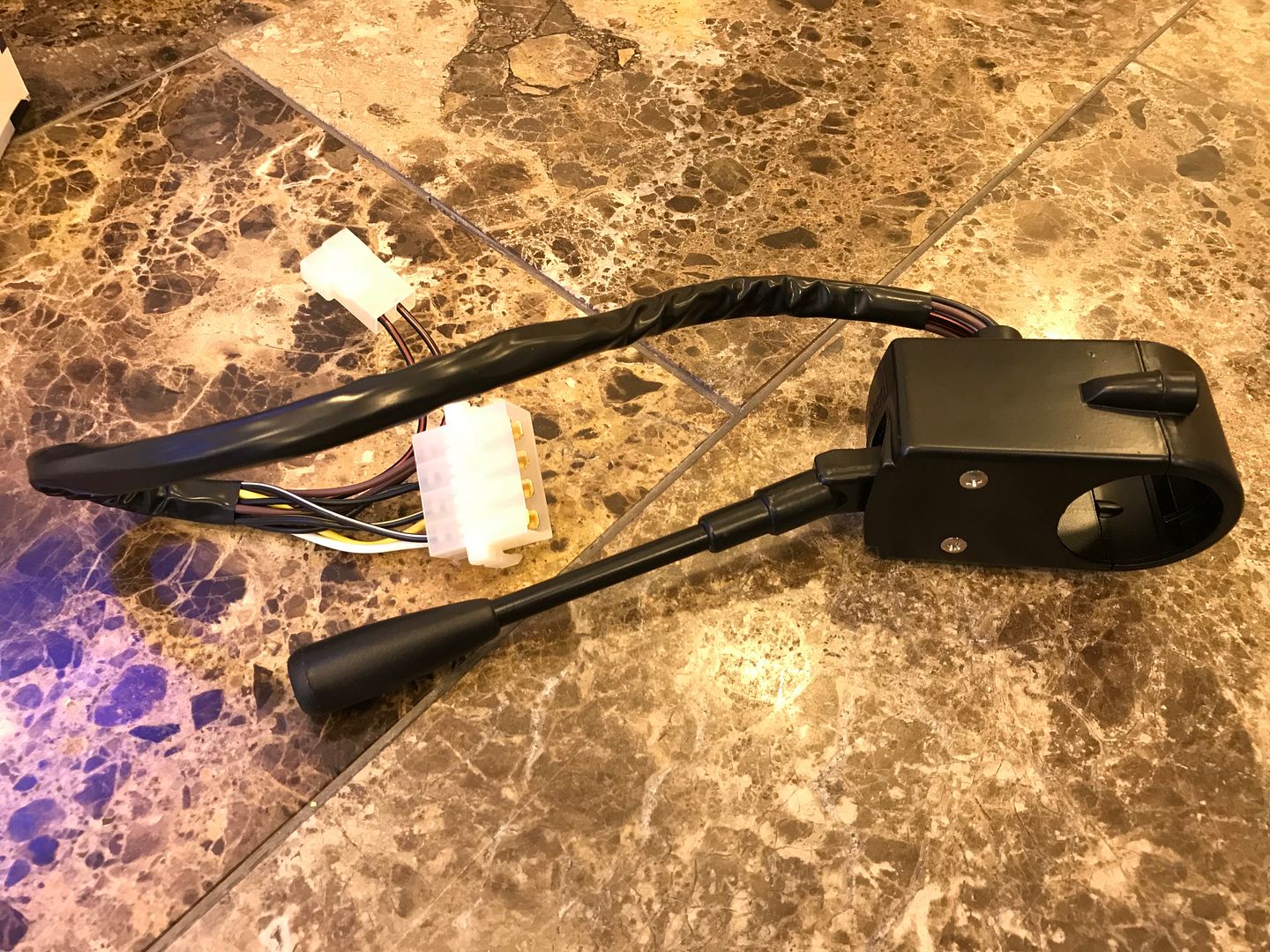
A stalk to control indicators, headlights, flashing of lights and horn to make driving the car a simpler experience.
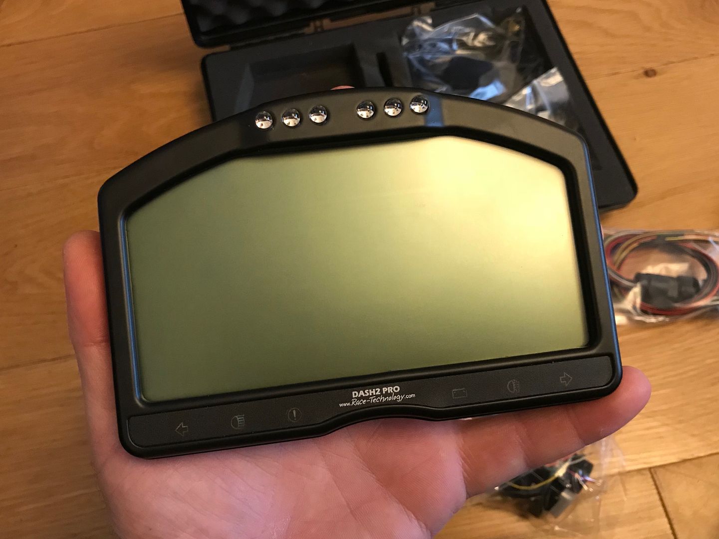
A Race Technology Dash 2 Pro dash with canbus to allow it communicate with the MBE 9A4 ECU and display/monitor/log any parameters the ECU is reading.
One Davis Craig EWP80 water pump with MBE amplifier to allow the ECU to control the speed (output) of the pump depending on temperature.
There is also an oil temperature sensor in there too, which will be installed into the dry sump oil tank.

A stalk to control indicators, headlights, flashing of lights and horn to make driving the car a simpler experience.

A Race Technology Dash 2 Pro dash with canbus to allow it communicate with the MBE 9A4 ECU and display/monitor/log any parameters the ECU is reading.

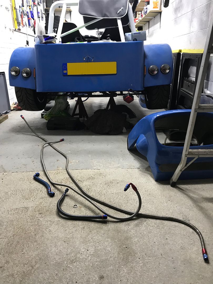
The original rubber lined braided petrol hoses had perished and were leaking so they have been removed
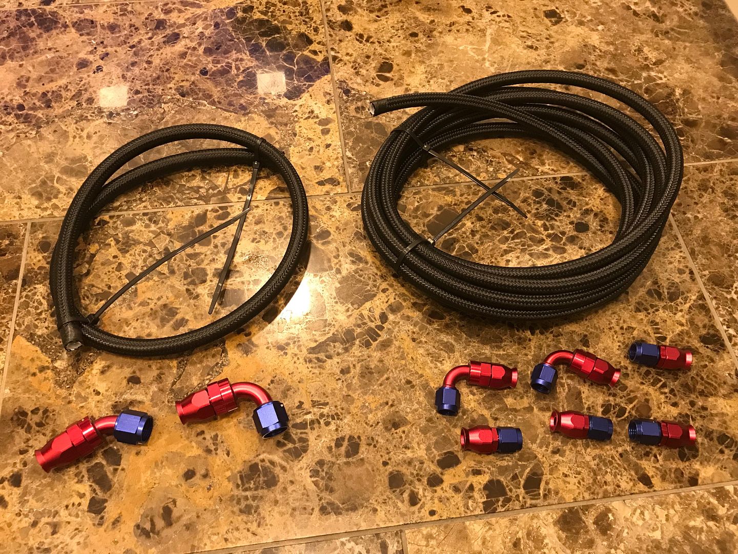
and are to be replaced by PTFE lined black braided hoses and new fittings
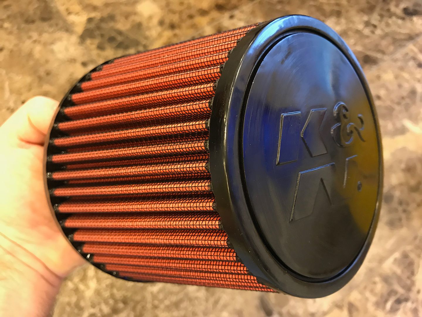
A new K&N filter which I plan to relocate behind the dash in the passenger compartment to breath nice cool air
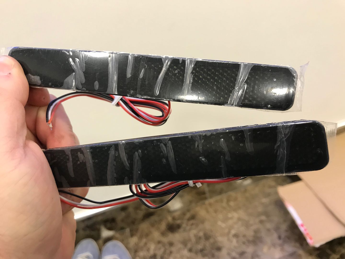
Some smoked foglights to mount low down at the rear of the chassis, once installed they should be very discreet.

and are to be replaced by PTFE lined black braided hoses and new fittings

A new K&N filter which I plan to relocate behind the dash in the passenger compartment to breath nice cool air

Some smoked foglights to mount low down at the rear of the chassis, once installed they should be very discreet.

Edited by Red16 on Sunday 23 December 19:00
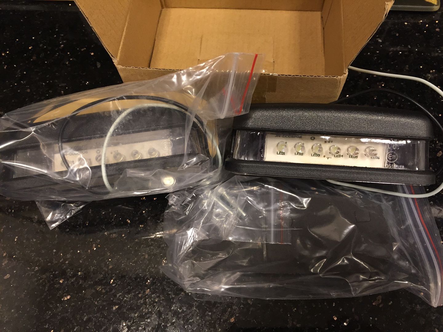
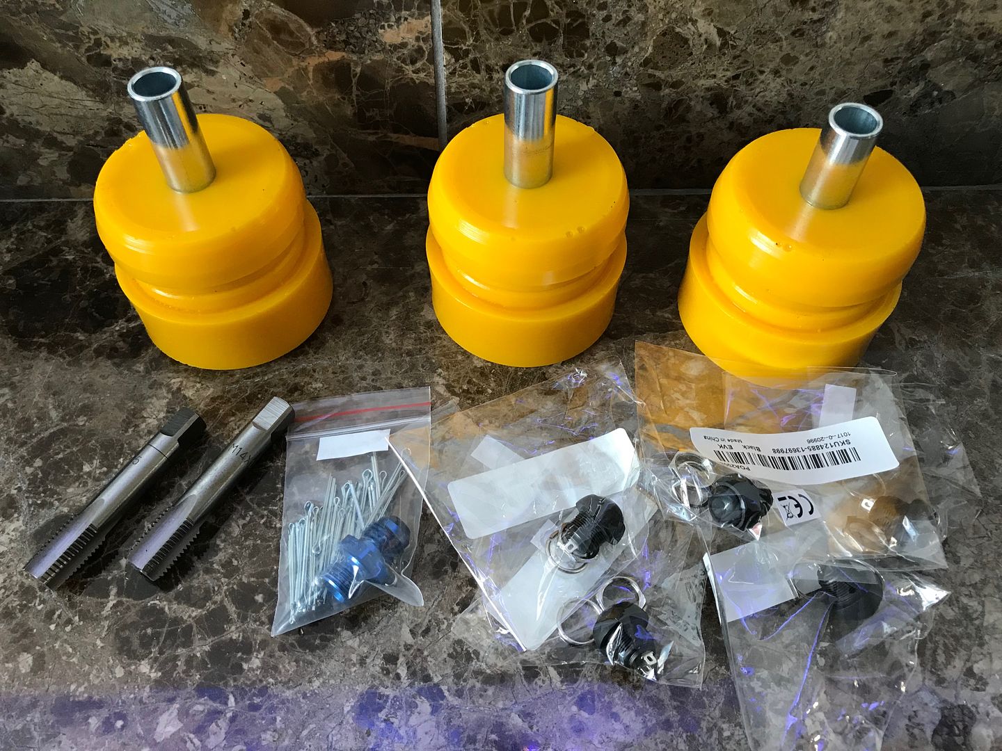
Some not so exciting rear number plate lights to replace the broken one that's currently fitted, obviously only installing one light not both of them.
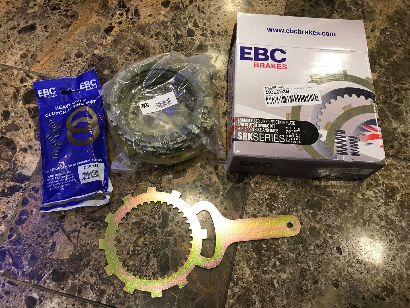
New EBC Kevlar friction plates and steel plates for the clutch, aswell as heavy duty springs.
Some polyurethane rear diff mounts. An M14x1.5mm tap set, M14x1.5mm to JIC6 fitting which will be used to make the oil return to the oil sight glass hole. And some black buttons to allow the Race Technology dash to be used.

New EBC Kevlar friction plates and steel plates for the clutch, aswell as heavy duty springs.

Some polyurethane rear diff mounts. An M14x1.5mm tap set, M14x1.5mm to JIC6 fitting which will be used to make the oil return to the oil sight glass hole. And some black buttons to allow the Race Technology dash to be used.

The engine is now out of the car and has been stripped down for inspection.
Last year I had the oil pressure warning light come on at hot idle, the light went away when the throttle was blipped and revs increased.
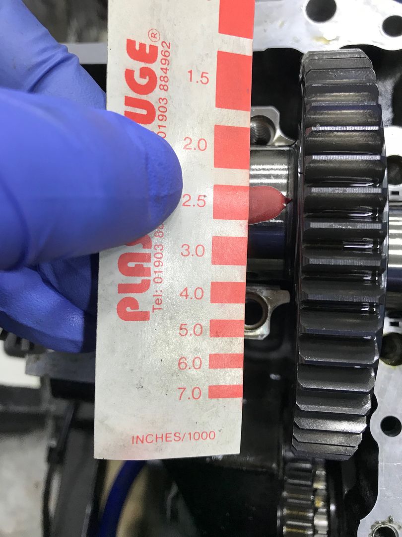
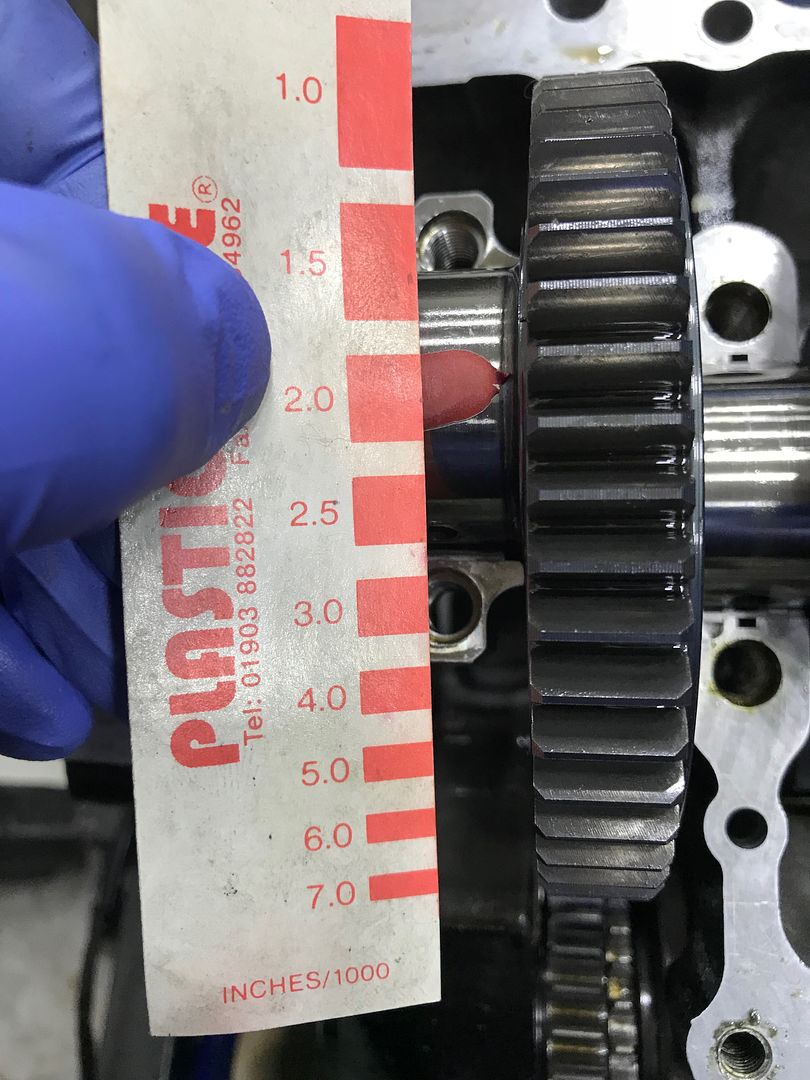
The main and big end bearings looked in good condition, much to my surprise.
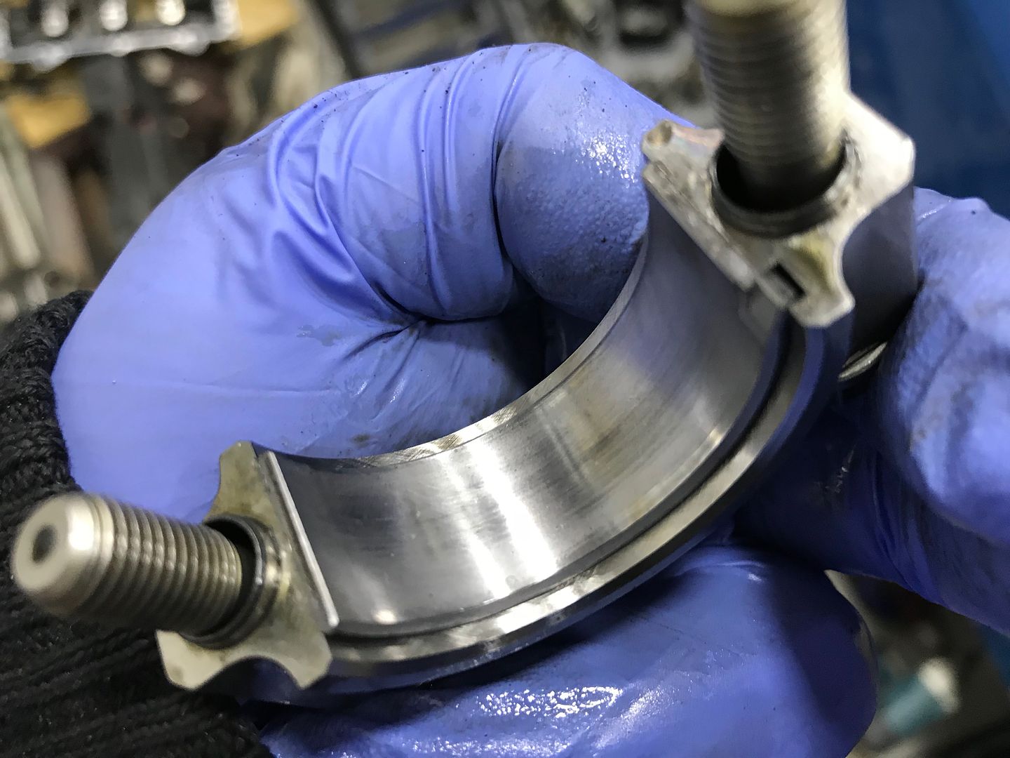
Bearing clearances measured somewhere between 0.002" and 0.0025", which is perfectly acceptable considering they were 0.002" when I last built it.
Last year I had the oil pressure warning light come on at hot idle, the light went away when the throttle was blipped and revs increased.
The main and big end bearings looked in good condition, much to my surprise.

Bearing clearances measured somewhere between 0.002" and 0.0025", which is perfectly acceptable considering they were 0.002" when I last built it.


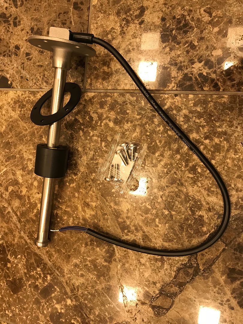
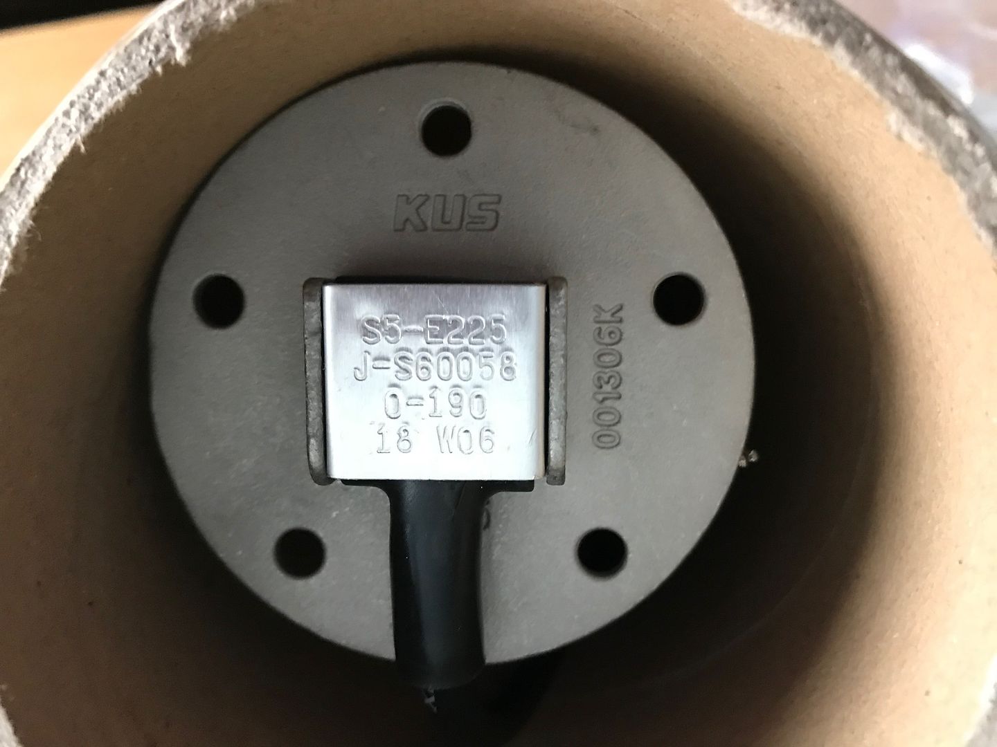
The standard ZX10R fuel sender never worked since installing the MBE 9A4 ECU, I've finally got around to buying a float style fuel level sender, this one is from KUS Auto, is 225mm long and has a range of 0-190 Ohms.
A few holes were drilled in the tank, the tanks was then flushed to clear away any swarf and debris
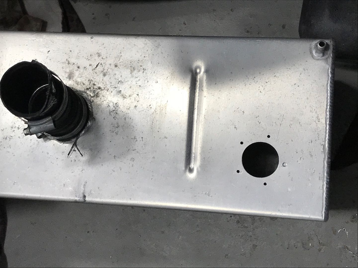
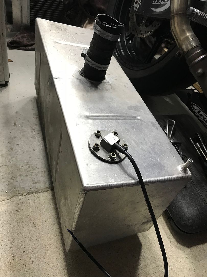
As the tank is too thin to tap threaded holes into it, I made some aluminium plates to mount on the underside with M6 taped holes in them to allow the sender to be bolted in position, making the plates was easy enough but mounting them inside the tanks with the sender unit was very fiddly. The sender installed looks like this.


A few holes were drilled in the tank, the tanks was then flushed to clear away any swarf and debris

As the tank is too thin to tap threaded holes into it, I made some aluminium plates to mount on the underside with M6 taped holes in them to allow the sender to be bolted in position, making the plates was easy enough but mounting them inside the tanks with the sender unit was very fiddly. The sender installed looks like this.

Gassing Station | Kit Cars | Top of Page | What's New | My Stuff