3428TM Build Log
Discussion


Apparently, Ford's Al9 ECU is a capable unit that can be improved on with a chip. Unmodified, it already has sequential injection, and with re-maps, can support quite a lot of power, for not very much money. That goes to the tuner.
Another route is to go with a standalone system like motec or Haltech but those are pricey. From there, there's a degradation of features and/or quality in parallel with cost. Right up to the point where you run into this.
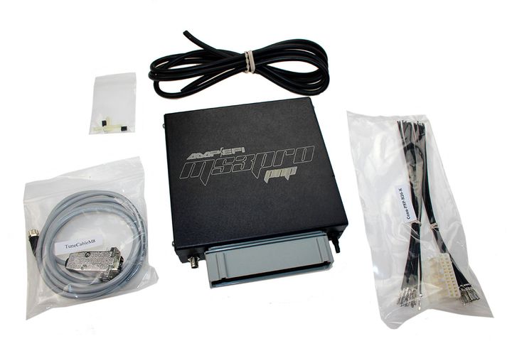
Then, the quality and features spike. Not only that, but I don't have to be a dealer, to tune it. And if that means you can avoid dealing with an absolute prima Donna named "Tom the Tuner", whom you'd rather push under a moving train, than allow them to touch your car, then isn't that worth something too?
It's going to be the first time I play with EFI, so I'm equally scared and excited.
And like the man with the knife said, . . . it won't be long now.
Another route is to go with a standalone system like motec or Haltech but those are pricey. From there, there's a degradation of features and/or quality in parallel with cost. Right up to the point where you run into this.
Then, the quality and features spike. Not only that, but I don't have to be a dealer, to tune it. And if that means you can avoid dealing with an absolute
prima Donna named "Tom the Tuner", whom you'd rather push under a moving train, than allow them to touch your car, then isn't that worth something too? It's going to be the first time I play with EFI, so I'm equally scared and excited.
And like the man with the knife said, . . . it won't be long now.
It was close to 100°F, today. Aluminum and stainless steel parts were getting so hot from laying in the sun, that we were throwing them in pool, to cool them enough to touch barehanded.
Nevertheless, we made good progress.
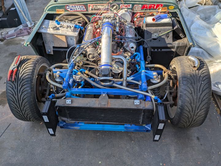
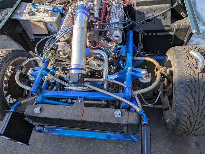
Lubrication plumbing: close to 100%
Coolant plumbing: close to 100%
Fuel plumbing: most supply/return lines made, still need to be installed. Still have to find/make fuel inlet pipes.
Induction system 100% (to be able to run) but I still need to make an air cleaner box.
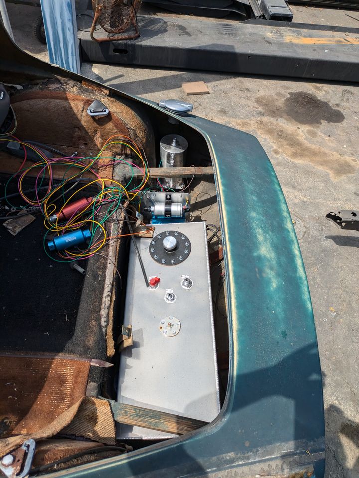
Since we moved the pre-oiler lower in the chassis, there's going to be lots of space for the ECU. Other than that, we're quickly running out of real estate.
Nevertheless, we made good progress.
Lubrication plumbing: close to 100%
Coolant plumbing: close to 100%
Fuel plumbing: most supply/return lines made, still need to be installed. Still have to find/make fuel inlet pipes.
Induction system 100% (to be able to run) but I still need to make an air cleaner box.
Since we moved the pre-oiler lower in the chassis, there's going to be lots of space for the ECU. Other than that, we're quickly running out of real estate.
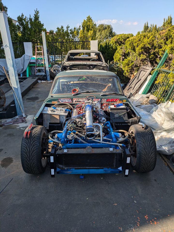
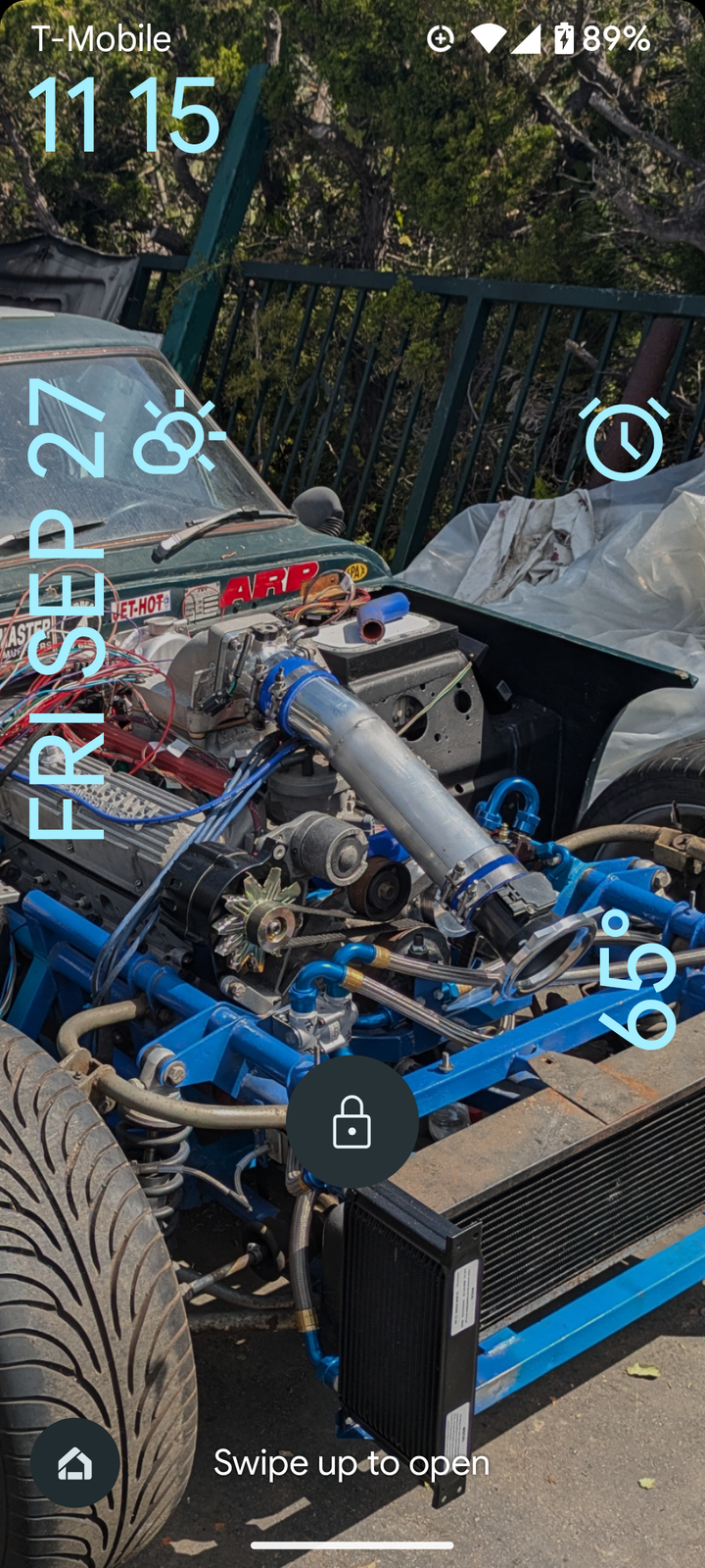
No progress for nine days, but this is my locked screen and it makes me happy every time I look at it.
Meanwhile, the new aluminum radiator and fuel filler neck arrived today. And I dug out new door rubber, a blue throttle cable, and the back footwells in my captious daily wagon are filled with all of the fluids except four fuel.
It's taken a lot to get to this point, but I'm finally happy with the level of almost 100% of everything that's been worked on.
I've been making, installing, and procuring hardware for brackets, and looking for missing fasteners and replacing them. Throttle linkages and cabling are getting closer. Fuel system is needs clamps and the tank side filler neck swapped out. 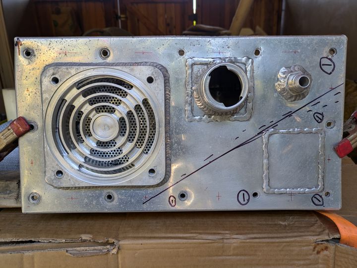
Also spent the past week going through the oil tank, making a little improvement at a time. It started with a good scrub inside and out. Then I used a C clamp to push the cratered bolt holes against a soft piece of wood wrapped in cloth. When the indent went the other way a bit, I backed off. Flat enough for a good seal, I think.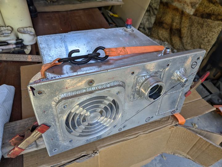
It also seems apparent that whoever overtightened the flange bolts in the first place did so in an effort to cure a seal. I'm going to double the number of fasteners along the flange and use large diameter (1"), thick washers as load spreaders. Along the way I also attracted a project helper. My neighbors have the privilege of housing and feeding her.
Also spent the past week going through the oil tank, making a little improvement at a time. It started with a good scrub inside and out. Then I used a C clamp to push the cratered bolt holes against a soft piece of wood wrapped in cloth. When the indent went the other way a bit, I backed off. Flat enough for a good seal, I think.
It also seems apparent that whoever overtightened the flange bolts in the first place did so in an effort to cure a seal. I'm going to double the number of fasteners along the flange and use large diameter (1"), thick washers as load spreaders.
It's an Oberg filter. The circular grille is one half of a sandwich with this stainless steel element in the middle. 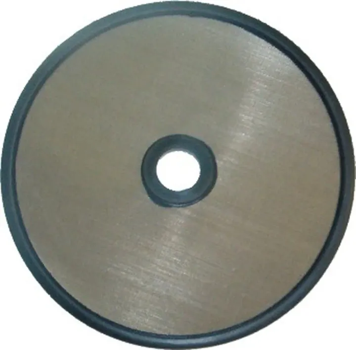
Oil enters the tank through the filter screen and then there's another, larger screen, then there's a corrugated, perforated baffle. It's 18qt. That means I should expect to have between 9 and 12 quarts in it (running) plus whatever additional capacity the engine itself, the pump, the coolers, filter, lines, and fittings need. Probably somewhere under 17 quarts total.
Oil enters the tank through the filter screen and then there's another, larger screen, then there's a corrugated, perforated baffle. It's 18qt. That means I should expect to have between 9 and 12 quarts in it (running) plus whatever additional capacity the engine itself, the pump, the coolers, filter, lines, and fittings need. Probably somewhere under 17 quarts total.
I've not seen such a thing before and, having converted your US quarts into a envisageable volume, wonder how many days it will take to reach operating temperature! 
Where will you site it? ...the usual place for a large oil tank is the boot, but it would be rather inaccessible there, surely?
Where will you site it? ...the usual place for a large oil tank is the boot, but it would be rather inaccessible there, surely?
Tank inside is 6×12×14. It's the flange that's costly in terms of real estate. Must be 1 1/2", at least.
I'm using oil to cool the engine. It has a thermostatic valve to bypass one of the coolers. I'm also going to add puller fans on the oil coolers and the radiator, if they're needed. I can go to The Valley for warm weather testing. Gets toasty there.
I'm using oil to cool the engine. It has a thermostatic valve to bypass one of the coolers. I'm also going to add puller fans on the oil coolers and the radiator, if they're needed. I can go to The Valley for warm weather testing. Gets toasty there.
Slow M said:
Tank inside is 6×12×14. It's the flange that's costly in terms of real estate. Must be 1 1/2", at least.
I'm using oil to cool the engine. It has a thermostatic valve to bypass one of the coolers. I'm also going to add puller fans on the oil coolers and the radiator, if they're needed. I can go to The Valley for warm weather testing. Gets toasty there.
I'm using oil to cool the engine. It has a thermostatic valve to bypass one of the coolers. I'm also going to add puller fans on the oil coolers and the radiator, if they're needed. I can go to The Valley for warm weather testing. Gets toasty there.

The folded sheet aluminum baffle ís a close fit, so the flange has to be external to facilitate its removal and reinstallation.
I've been thinking of a flange that's made of something like 7/16" or 1/2" plate, in the vertical orientation, but still external. That way it'll save the most space but still work with the baffle. And it could potentially add capacity when coupled with an equal counterpart on the mating flange.
By the way, the placement also has to do with pushing all parts as close as possible to the mass centroid. Also keeps the line runs shorter, for less overall weight and less strain on the pump.
Gassing Station | TVR Classics | Top of Page | What's New | My Stuff