95 Griff random wires
Discussion


So another thread I’m starting which I hope will get me through tracing random ripped out wires. I have a few, some easier to trace than others so first one is below:
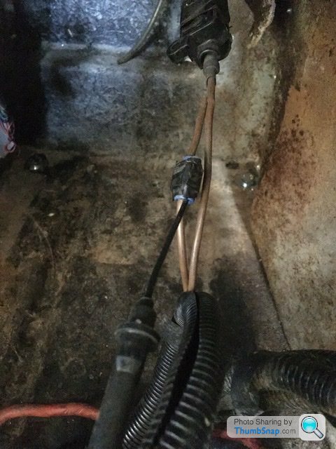
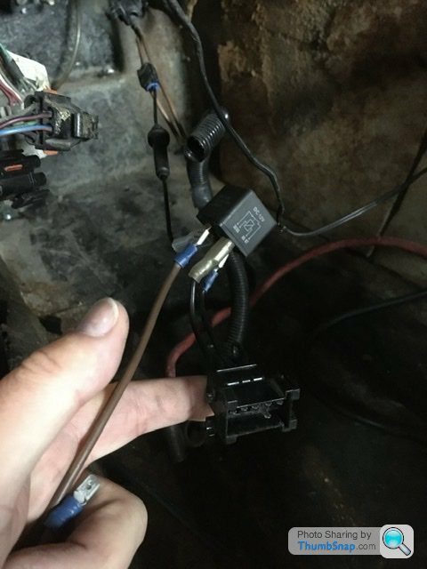
First wire is shown is in the picture below. It’s passenger side (rhd) attached to a micro switch on the central locking solenoid. It has a blade fuse attached mid way but it’s been pulled off somewhere hence a bare end on the cable.


If I had dismantled the car myself I would have taken pictures accordingly for reassembly. I didn’t rip these wires.
My fingers are crossed and thanks in advance for any help
First wire is shown is in the picture below. It’s passenger side (rhd) attached to a micro switch on the central locking solenoid. It has a blade fuse attached mid way but it’s been pulled off somewhere hence a bare end on the cable.
If I had dismantled the car myself I would have taken pictures accordingly for reassembly. I didn’t rip these wires.
My fingers are crossed and thanks in advance for any help
Belle427 said:
I seem to remember a mod for a mag switch at the rear somewhere to open the boot using a microswitch here.
Worth checking.
That makes sense. My car had that mod so it’s for that then Worth checking.
I’ll have another look in the morning and hopefully confirm that

Cheers guys
I’ll post next random wire soon

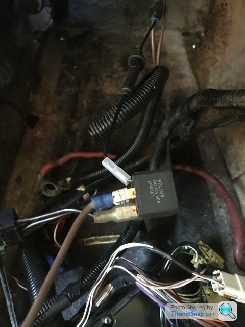
See if it energises in the crank position, if so it's the world famous hot start mod.
It's a terrible botch whatever it is.
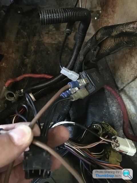
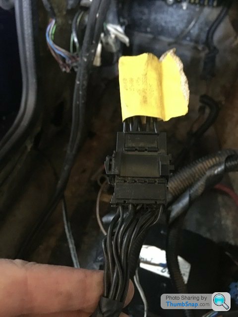
Multiple blacks are normally immobiliser related so be careful!
Usually the hot start mod is spliced into those blacks in the connector.
It's a terrible botch whatever it is.
Multiple blacks are normally immobiliser related so be careful!
Usually the hot start mod is spliced into those blacks in the connector.
Edited by Belle427 on Monday 20th March 08:35
Belle427 said:
See if it energises in the crank position, if so it's the world famous hot start mod.
It's a terrible botch whatever it is.
Multiple blacks are normally immobiliser related so be careful!
Usually the hot start mod is spliced into those blacks in the connector.
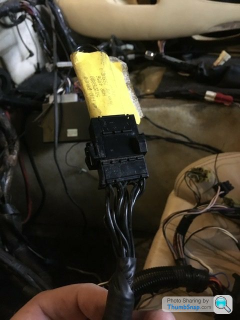
Right so I seem to have had an unspliced connection fitted onto the bunch of black wires. Which makes that scotch lock relay redundant.It's a terrible botch whatever it is.
Multiple blacks are normally immobiliser related so be careful!
Usually the hot start mod is spliced into those blacks in the connector.
Edited by Belle427 on Monday 20th March 08:35
The info from Bertram-Hill is interesting. The mods to wiring for the windows and windscreen I’ll definitely do. I might as well move the fuse board to the glove box as well while I have good access to the wiring.
A few years back I did modify the battery box to slide a battery in and out without removing the battery box via the bolts through the floor. I think now is the ideal time to finish that mod thoroughly.
A few years back I did modify the battery box to slide a battery in and out without removing the battery box via the bolts through the floor. I think now is the ideal time to finish that mod thoroughly.
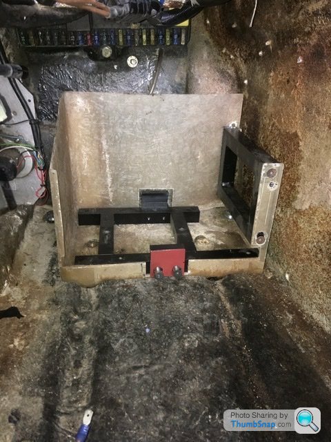
Here is the cut up and altered battery box.
If you notice the grooves in the body floor, the opposite is present on the base of the battery box but to fit within those grooves the box needed a bit of trimming off the right hand side and the right hand rear corner to clear the body mounting bolt. I made a frame to fit within so it clamps the box from underneath then made a pair of clamps to hold the base of the battery. So that allows removal of the battery by removing the red painted clamp. The battery then slides out. It still needs finishing but the basics are there.
BIG DUNC said:
That looks good. I toyed with the idea of doing something similar, but in the end I refitted the original battery box.
Cheers. Just thought might as well finish this while everything is stripped out. The fuse box behind I’m going to move to the glove box which then gives space to mount the ecu behind the battery box. The rats nest of wires on the battery isn’t the greatest by tvr lol.I’m never happy with the wiring and have been doing some further mods to mine whilst I’m recommissioning, kind of finishing a project (with upgrades) from before it went into storage. The team who’ve done the body off have allowed me to play in the footwell and do the stereo etc. whilst we had dash out - bless ‘em!!
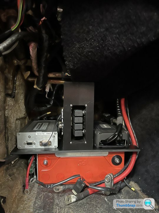
Excuse the carpet, not fully fitted/finished yet. Or all the last wiring when the photo was taken - it is all done now. I already had the ECU/engine loom custom made. Previously hiding the ECU above glovebox. Junked the engine loom completely for custom made loom when I did the ECU.
I have run an Odyssey battery for years and now I’ve sorted the whole footwell area out with ECU, amplifier, mini relay bank in custom bracket I printed up. I have no need for extended footwell length, this is almost exactly the same, <2cm better than with std battery box, but no significant gain.
You could do the same battery mod without all the loom/ECU changes I’ve done. Battery is bolted to floor in std Odyssey cage, lightly modded with an ABS plastic plinth, I ended up using Velcro to attach the plinth versus a mechanical fixing for ease of removal of necessary. Battery removal is 2 bolts under the car and it slides out, cage stays in place.
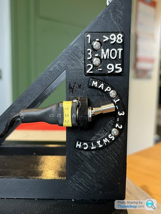
I had no desire for battery in boot, behind seats is also just more useful space lost. The footwell is best place for it and now it’s a bit more organised, access to fuses slightly easier and I’ve found a home for the amplifier for the stereo upgrade I’ve been doing as well. ECU easily accessible with 3 way map switch mounted to 3d printed bracket - which supports footboard. A front cover for the battery will get printed up when I’ve had time to design it.
ECU, bracket and amplifier all bolted to plinth using M3’s into inserts set into the plastic, easy done with a soldering gun etc.
I junked the hot start mod I had and initially I have upgraded the 20yr old 35mm cable to 50mm and will see how that goes before tackling the immobiliser issue as a longer term fix.
Ideally I’d junk the whole lot and go with a PDM unit running the car, but I don’t have time for all that!!
Excuse the carpet, not fully fitted/finished yet. Or all the last wiring when the photo was taken - it is all done now. I already had the ECU/engine loom custom made. Previously hiding the ECU above glovebox. Junked the engine loom completely for custom made loom when I did the ECU.
I have run an Odyssey battery for years and now I’ve sorted the whole footwell area out with ECU, amplifier, mini relay bank in custom bracket I printed up. I have no need for extended footwell length, this is almost exactly the same, <2cm better than with std battery box, but no significant gain.
You could do the same battery mod without all the loom/ECU changes I’ve done. Battery is bolted to floor in std Odyssey cage, lightly modded with an ABS plastic plinth, I ended up using Velcro to attach the plinth versus a mechanical fixing for ease of removal of necessary. Battery removal is 2 bolts under the car and it slides out, cage stays in place.
I had no desire for battery in boot, behind seats is also just more useful space lost. The footwell is best place for it and now it’s a bit more organised, access to fuses slightly easier and I’ve found a home for the amplifier for the stereo upgrade I’ve been doing as well. ECU easily accessible with 3 way map switch mounted to 3d printed bracket - which supports footboard. A front cover for the battery will get printed up when I’ve had time to design it.
ECU, bracket and amplifier all bolted to plinth using M3’s into inserts set into the plastic, easy done with a soldering gun etc.
I junked the hot start mod I had and initially I have upgraded the 20yr old 35mm cable to 50mm and will see how that goes before tackling the immobiliser issue as a longer term fix.
Ideally I’d junk the whole lot and go with a PDM unit running the car, but I don’t have time for all that!!
Edited by Johno on Tuesday 21st March 22:38
Gassing Station | Griffith | Top of Page | What's New | My Stuff