95 4lt Fuel gauge wireing
Discussion


Hi
I have just replace the dash, making careful notes of which wires go where. Not careful enough!!
I have the larger fuel gauge with a low fuel warning light, all was working well. upon wiring as per my notes the fuel gauge goes off the scale and the warning light is dim. There are 4 wires excluding the bulb + and -. can anyone point me in the right direction. Many thanks.
Please post the cable colours
This may help
Green is the feed to all the instruments (should be stabilized but isn't).
Black is the ground (for instrument & lighting)
Red/white is the lights.
To the Tank sender/warning are:
Blue (common)
Green/black(tank gauge)
Red/Black (low level warning)
Copied from https://www.pistonheads.com/gassing/topic.asp?h=0&...
Edited by Penelope Stopit on Monday 14th May 14:15
I have been having problems with my fuel gauge / sender.
I found the sender unit has a resistance range from about 30-430 ohms.
I contacted ETB to see if they had any information they could share. They were very helpful and provided me with this drawing.
I hope it can help someone else
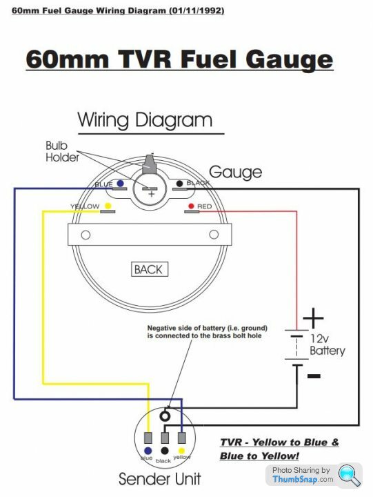
The text that came with the mail was:-
The yellow and blue markings on the gauge and sender are these 2 varying resistances. (On TVR they swapped them, so blue on gauge goes to yellow on sender and vice versa). The black / centre terminal on the sender operates the low fuel LED. The brass bolt hole on the sender earths the whole system (there is no earth to the gauge).
I found the sender unit has a resistance range from about 30-430 ohms.
I contacted ETB to see if they had any information they could share. They were very helpful and provided me with this drawing.
I hope it can help someone else
The text that came with the mail was:-
The yellow and blue markings on the gauge and sender are these 2 varying resistances. (On TVR they swapped them, so blue on gauge goes to yellow on sender and vice versa). The black / centre terminal on the sender operates the low fuel LED. The brass bolt hole on the sender earths the whole system (there is no earth to the gauge).
Gassing Station | Chimaera | Top of Page | What's New | My Stuff