VR Sensor Air Gap
Discussion


Thanks, this is inline with my research.
This weekend I checked my VR sensor air gap and it had been set by my engine management installers at just 0.4mm!, this was not slippage as the sensor is very secure as is the bracket, the bracket bolts were found to be extremely tight too so the air gap had been intentionally set to 0.4mm , I regapped to a far more reasonable but still conservative 0.8mm and the car immediately idled and ran smoother, noticeably smoother!
I have since researched the outcome of a VR sensor that's been set too close to the trigger wheel and essentially it gives the ECU are really hard time making sense of the signal, set the air gap too tight and the sensor output signal becomes unstable, the wave form it produces becomes inconsistent and can indeed be completely lost for a few milliseconds.
The ECU struggles to process this poor input signal and the results are poor ignition coil and injector control, micro misfires are the common result of a VR sensor being set too close to the trigger wheel causing an erratic idle and poor drivabilty. Both the way too tight 0.4mm gap the installers set my VR sensor at and my recently discovered battery terminal/cable connection issues clear have combined to make some significant improvements in the way the car idles and drives.
My idle is even smoother, throttle response is sharper and drivability especially below 2,000rpm is greatly enhanced. The engine and so the whole car feels way more refined, even above 2,000rpm there seems to be a smoothing effect like all the high frequency vibrations once felt throughout the car but especially through my metal Leven throttle pedal have gone.
It wasn't like it was dreadful before, more that the changes have brought something so much better that the comparison is very pronounced. Even the wife without me even prompting her said "wow the TVR feels a lot smoother", she would be the first to admit she has no mechanical aptitude whatsoever so believe me for her to say that is praise indeed.
I knew I had voltage/earthing/charging issues which is why I've been focussing on this area for a while now, but it turns out the issue I was looking for were all at my battery terminals, this and opening up my VR sensor gap have together delivered fantastic improvements.
My research has also revealed setting a VR sensor too close to the trigger wheel can damage it, not necessarily physical damage as such although this is always a consideration, but internal electrical damage within the sensor. I believe my 7 year old pattern part sensor has had a hard life being run so close to the trigger wheel all these years, its also been covered in a thick jacket of oil and road dirt for a lot of this time, I only noticed the build-up of grime a few weeks ago and cleaned a ton of goo from it.
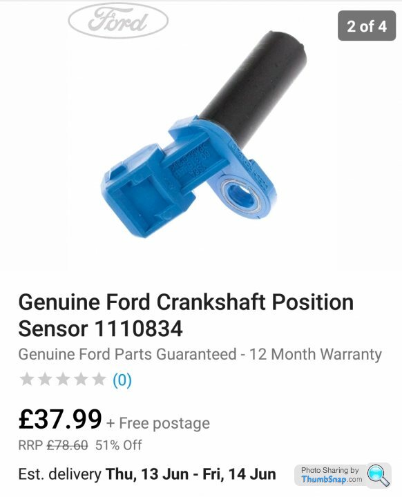
So with all this in mind and the the real improvements I've seen from increasing my VR sensor air gap I've decided to treat the car to a brand new genuine Ford sensor, with such a critical job to do I figured its not worth messing about with a cheap pattern part as it only saves be £18 and to be frank I've become very fed up with finding myself at the side of the road because of poor quality components being fitted to my car.
Fuse holders that fail before the fuse itself and no name pattern part idle valves are all now banished to the bin where they belong, all to be replaced with genuine Bosch, Ford and GM sensors and components and proper MtA midi fuse holders and fuses.
Dave.
This weekend I checked my VR sensor air gap and it had been set by my engine management installers at just 0.4mm!, this was not slippage as the sensor is very secure as is the bracket, the bracket bolts were found to be extremely tight too so the air gap had been intentionally set to 0.4mm
, I regapped to a far more reasonable but still conservative 0.8mm and the car immediately idled and ran smoother, noticeably smoother! I have since researched the outcome of a VR sensor that's been set too close to the trigger wheel and essentially it gives the ECU are really hard time making sense of the signal, set the air gap too tight and the sensor output signal becomes unstable, the wave form it produces becomes inconsistent and can indeed be completely lost for a few milliseconds.
The ECU struggles to process this poor input signal and the results are poor ignition coil and injector control, micro misfires are the common result of a VR sensor being set too close to the trigger wheel causing an erratic idle and poor drivabilty. Both the way too tight 0.4mm gap the installers set my VR sensor at and my recently discovered battery terminal/cable connection issues clear have combined to make some significant improvements in the way the car idles and drives.
My idle is even smoother, throttle response is sharper and drivability especially below 2,000rpm is greatly enhanced. The engine and so the whole car feels way more refined, even above 2,000rpm there seems to be a smoothing effect like all the high frequency vibrations once felt throughout the car but especially through my metal Leven throttle pedal have gone.
It wasn't like it was dreadful before, more that the changes have brought something so much better that the comparison is very pronounced. Even the wife without me even prompting her said "wow the TVR feels a lot smoother", she would be the first to admit she has no mechanical aptitude whatsoever so believe me for her to say that is praise indeed.
I knew I had voltage/earthing/charging issues which is why I've been focussing on this area for a while now, but it turns out the issue I was looking for were all at my battery terminals, this and opening up my VR sensor gap have together delivered fantastic improvements.
My research has also revealed setting a VR sensor too close to the trigger wheel can damage it, not necessarily physical damage as such although this is always a consideration, but internal electrical damage within the sensor. I believe my 7 year old pattern part sensor has had a hard life being run so close to the trigger wheel all these years, its also been covered in a thick jacket of oil and road dirt for a lot of this time, I only noticed the build-up of grime a few weeks ago and cleaned a ton of goo from it.
So with all this in mind and the the real improvements I've seen from increasing my VR sensor air gap I've decided to treat the car to a brand new genuine Ford sensor, with such a critical job to do I figured its not worth messing about with a cheap pattern part as it only saves be £18 and to be frank I've become very fed up with finding myself at the side of the road because of poor quality components being fitted to my car.
Fuse holders that fail before the fuse itself and no name pattern part idle valves are all now banished to the bin where they belong, all to be replaced with genuine Bosch, Ford and GM sensors and components and proper MtA midi fuse holders and fuses.
Dave.
First time I've ever heard of this ..
I always set my sensors up by eye, I learned years ago that as long as there's a gap which is there-abouts then that's fine.
I do use a trigger wheel that's a bit larger diameter than most people though, so the effective linear speed of the sensor past the teeth is greater than with a small diameter wheel, which might help me.
On that point though, I've seen sensors actually being ground away on the trigger wheel with no apparent issues. This is incredibly common on the later tvrs - unless the sensor has been spaced out with a small washer .. you remove the crank sensor for cleaning at service to find the end ground away by the wheel.
Maybe the canems is more sensitive to this, or maybe the non OE sensor type makes the effect more noticeable, but the effect on your car's running that you've experienced isn't something I can say I've experienced before.
If it's better, it's better though, so worth doing in your case.
- would have been interesting to see a data log or osciloscope trace to prove it
spitfire4v8 said:
First time I've ever heard of this ..
I always set my sensors up by eye, I learned years ago that as long as there's a gap which is there-abouts then that's fine.
I do use a trigger wheel that's a bit larger diameter than most people though, so the effective linear speed of the sensor past the teeth is greater than with a small diameter wheel, which might help me.
On that point though, I've seen sensors actually being ground away on the trigger wheel with no apparent issues. This is incredibly common on the later tvrs - unless the sensor has been spaced out with a small washer .. you remove the crank sensor for cleaning at service to find the end ground away by the wheel.
Maybe the canems is more sensitive to this, or maybe the non OE sensor type makes the effect more noticeable, but the effect on your car's running that you've experienced isn't something I can say I've experienced before.
If it's better, it's better though, so worth doing in your case.
I guess to an extent it depends on which signal conditioning IC is being used by the ECU and what the supporting circuitry does. The trick is clearly to make sure that the signal to noise ratio is correct, and I can see that if there are other electrically noisy components in area that noise may be picked up on the sensor input, but I don't understand how a smaller sensor gap could cause that noise to be amplified. A smaller gap should just produce larger signal voltages at the sensor (I suppose the conditioner might ignore them if they got too large?). I would be interested to see the reference material on it.I always set my sensors up by eye, I learned years ago that as long as there's a gap which is there-abouts then that's fine.
I do use a trigger wheel that's a bit larger diameter than most people though, so the effective linear speed of the sensor past the teeth is greater than with a small diameter wheel, which might help me.
On that point though, I've seen sensors actually being ground away on the trigger wheel with no apparent issues. This is incredibly common on the later tvrs - unless the sensor has been spaced out with a small washer .. you remove the crank sensor for cleaning at service to find the end ground away by the wheel.
Maybe the canems is more sensitive to this, or maybe the non OE sensor type makes the effect more noticeable, but the effect on your car's running that you've experienced isn't something I can say I've experienced before.
If it's better, it's better though, so worth doing in your case.
- would have been interesting to see a data log or osciloscope trace to prove it
I don't think linear speed of the teeth will be having an effect in your case as a larger diameter wheel will naturally have wider teeth thereby keeping the frequency constant (assuming the same number of teeth).
I run a hall sensor. I noted when building my system that the most common problem people had was with VR sensors and loss of sync / wrong sync / weird triggering issues, so I just stayed away from them.
spitfire4v8 said:
First time I've ever heard of this ..
I always set my sensors up by eye, I learned years ago that as long as there's a gap which is there-abouts then that's fine.
I do use a trigger wheel that's a bit larger diameter than most people though, so the effective linear speed of the sensor past the teeth is greater than with a small diameter wheel, which might help me.
On that point though, I've seen sensors actually being ground away on the trigger wheel with no apparent issues. This is incredibly common on the later tvrs - unless the sensor has been spaced out with a small washer .. you remove the crank sensor for cleaning at service to find the end ground away by the wheel.
Maybe the canems is more sensitive to this, or maybe the non OE sensor type makes the effect more noticeable, but the effect on your car's running that you've experienced isn't something I can say I've experienced before.
If it's better, it's better though, so worth doing in your case.
Knowing the principles of variable reluctance a change in the trigger wheel size will quite clearly make a difference as the signal developed by the VR sensor is proportional to speed.I always set my sensors up by eye, I learned years ago that as long as there's a gap which is there-abouts then that's fine.
I do use a trigger wheel that's a bit larger diameter than most people though, so the effective linear speed of the sensor past the teeth is greater than with a small diameter wheel, which might help me.
On that point though, I've seen sensors actually being ground away on the trigger wheel with no apparent issues. This is incredibly common on the later tvrs - unless the sensor has been spaced out with a small washer .. you remove the crank sensor for cleaning at service to find the end ground away by the wheel.
Maybe the canems is more sensitive to this, or maybe the non OE sensor type makes the effect more noticeable, but the effect on your car's running that you've experienced isn't something I can say I've experienced before.
If it's better, it's better though, so worth doing in your case.
- would have been interesting to see a data log or osciloscope trace to prove it
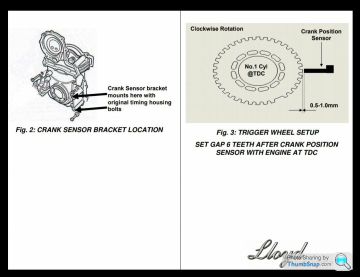
It's always been my experience there are very good reasons why clear specifications exist for this type of critical sensor clearance so I try to follow them, I found my air gap to be set by the installers at 0.4mm which is a lot tighter than the Canems manual recommends at 1.5mm.

Strangely even the installers own manual states 0.5mm to 1.0mm so I have no idea why I got 0.4mm.
I'm not quite sure why the installers would quite different figures to the ECU designer but there it is, perhaps this and the 0.4mm air gap I got was the function of being an early adopter and maybe things have been learned since my car received its engine management installation, actually that's not a maybe as I know an awful lot has been learned by everyone since then!
Anyway, I open the gap from my tight as a nun's chuff 0.4mm setting to 0.8mm which I felt walked a nice line and go for a drive to find the car is most definitely smoother idling and driving, it's not a maybe a bit better thing..... its an unquestionably better thing!
Thems the facts and very happy I am with them too

ric355 said:
I run a hall sensor. I noted when building my system that the most common problem people had was with VR sensors and loss of sync / wrong sync / weird triggering issues, so I just stayed away from them.
The above is of interest to me as is an option I am exploring myself, my Canems ECU will accept a Hall sensor and I hear they are less susceptible to EMI issues which I've most definitely suffered from in the past.Let me try my new and genuine Ford VR sensor, following this a Hall sensor may well be my nest step

Edited by ChimpOnGas on Monday 10th June 14:57
I use inductive triggers so the amplitude of the wave is proportional to the speed of the trigger past the sensor. It's the reason why I use a slightly oversize trigger wheel compared to most kits as at cranking I want the ecu to properly "see" the wheel at around (or under with a poor battery) 100rpm or so cranking speed. The oversize wheel gives a higher signal amplitude for any given angular velocity, because the equilavlent linear speed of the teeth past the sensor is greater.
Here's a great test of wheels and speeds :
https://trigger-wheels.com/store/contents/en-uk/d2...
Here's a great test of wheels and speeds :
https://trigger-wheels.com/store/contents/en-uk/d2...

spitfire4v8 said:
I use inductive triggers so the amplitude of the wave is proportional to the speed of the trigger past the sensor. It's the reason why I use a slightly oversize trigger wheel compared to most kits as at cranking I want the ecu to properly "see" the wheel at around 100rpm or so. The oversize wheel gives a higher signal amplitude for any given angular velocity, because the equilavlent linear speed of the teeth past the sensor is greater.
Here's a great test of wheels and speeds :
https://trigger-wheels.com/store/contents/en-uk/d2...
My Canems system definitely takes a few seconds to pick up the crank signal, I'd be interested to know how quickly your setup picks it up?Here's a great test of wheels and speeds :
https://trigger-wheels.com/store/contents/en-uk/d2...
The gap increase I'm covering here was definitely an improvement and that includes starting, the ECU clearly likes a bigger gap so I most certainly will not be returning to the 0.4mm I was given

ChimpOnGas said:
The above is of interest to me as is an option I am exploring myself, my Canems ECU will accept a Hall sensor and I hear they are less susceptible to EMI issues which I've most definitely suffered from in the past.
Let me try my new and genuine Ford VR sensor, following this a Hall sensor may well be my nest step
My hall sensor is a BMW 1214170327. I'm running it with a 5v supply. It switches to ground if I remember correctly but I wasn't sure whether it floated or supplied the input voltage when not switched, so I stuck with 5v so that I was sure it could go straight into the ECU.Let me try my new and genuine Ford VR sensor, following this a Hall sensor may well be my nest step
Edited by ChimpOnGas on Monday 10th June 14:57
ric355 said:
I guess to an extent it depends on which signal conditioning IC is being used by the ECU and what the supporting circuitry does. The trick is clearly to make sure that the signal to noise ratio is correct, and I can see that if there are other electrically noisy components in area that noise may be picked up on the sensor input, but I don't understand how a smaller sensor gap could cause that noise to be amplified. A smaller gap should just produce larger signal voltages at the sensor (I suppose the conditioner might ignore them if they got too large?). I would be interested to see the reference material on it.
I don't think linear speed of the teeth will be having an effect in your case as a larger diameter wheel will naturally have wider teeth thereby keeping the frequency constant (assuming the same number of teeth).
I run a hall sensor. I noted when building my system that the most common problem people had was with VR sensors and loss of sync / wrong sync / weird triggering issues, so I just stayed away from them.
What I'm being told is for VR you need a quality conditioning solution and apparently not all VR conditioner boards are created equal, maybe this fact combined with me running a well used pattern part sensor is the reason I saw such an improvement from open my air gap?I don't think linear speed of the teeth will be having an effect in your case as a larger diameter wheel will naturally have wider teeth thereby keeping the frequency constant (assuming the same number of teeth).
I run a hall sensor. I noted when building my system that the most common problem people had was with VR sensors and loss of sync / wrong sync / weird triggering issues, so I just stayed away from them.
While I'll take the improvements with a smile something is definitely still not right in the VR department, very occasionally at around 1,600rpm I am seeing an RPM drop out accompanied by what what I would describe as a monetary hard misfire.
I'm not a fan of the parts darts approach but before I get scoping it's getting a new genuine Ford VR sensor, after all my pattern part sensor has done 7 years service and on my TVR that means during that time it's been subjected to not inconsiderable levels of oil contamination, heat and vibration.
With very real improvements found in a simple gap change and the nature of the fault also pointing me in the VR direction, I don't feel the investment in a new genuine sensor is the greatest leap of faith... especially given the very affordable cost of the thing.
While these things are generally pretty reliable VR sensor failure is far from uncommon, I know the one fitted to my car is not a genuine part made to strict OEM standards and I know it's had a hard life...... so lets hope I'm on the right track
ric355 said:
ChimpOnGas said:
The above is of interest to me as is an option I am exploring myself, my Canems ECU will accept a Hall sensor and I hear they are less susceptible to EMI issues which I've most definitely suffered from in the past.
Let me try my new and genuine Ford VR sensor, following this a Hall sensor may well be my nest step
My hall sensor is a BMW 1214170327. I'm running it with a 5v supply. It switches to ground if I remember correctly but I wasn't sure whether it floated or supplied the input voltage when not switched, so I stuck with 5v so that I was sure it could go straight into the ECU.Let me try my new and genuine Ford VR sensor, following this a Hall sensor may well be my nest step
Edited by ChimpOnGas on Monday 10th June 14:57
Dave.

This is an interesting read:
https://fullfunctioneng.com/info/Hall%20vs%20VR.pd...
Its especially worth digesting the part about how VR sensors make more voltage the closer they are set to the trigger wheel, of course as voltage increases so does the potential for noise/interference (EMI), actually the paper discusses how increasing the distance from the ferrous material is a solution to the inherent flaw all VR sensors come with...... IE by design they are perfect little EMI generators themselves!
Closer = higher voltage and increases EMI while further away decreases voltage reducing EMI until eventually its so far away the effects of reluctance are lost, this all makes perfect sense, moreover it tells us why VR sensor air gap specifications never just say from as close as you can get it to say 1.0mm.
Clearly too close is actually a very bad thing! Indeed in many respects too close is worse than too far away because at least if the gap is too wide the engine most likely will simply fail to start!
We now have very strong evidence to support a theory that says the reason my engine idles and drives so much better since I opened the gap from the ridiculously close 0.4mm the installers gave me to the much more reasonable 0.8mm is because my sensor voltage is now within the design limits of both the sensor and what my ECU can tolerate in the way of EMI produced by said sensor.
I also now understand why I was advised by a reputable source that a VR sensor can actually become damaged electrically when placed too close to the trigger wheel, too close and the sensor may make more voltage than it's designers intended, not only will it generate more EMI than the engine management system can tolerate it could also be enough to start damaging the sensor's delicate internals IE is fine wire coil windings.
See, a little study goes a long way
I feel an experiment coming on. Trigger wheel mounted to a pillar drill and sensor on an adjustable mount. Measure the output signal with a scope. Compare sensors and sensor distance. See if the signal amplitude significantly changes while adjusting sensor distance between 0.4 and 2mm? Also observe the signal waveform. Check for signal jitter and also noise spikes on the signal. Ideally you also need a high speed counter to count the pulses for a fixed amount of rotation, this will confirm it’s accurate.
And directly from the Canems manual, I give you.......

Maybe all we need is a little help from Edwin Hall

Maybe all we need is a little help from Edwin Hall
ric355 said:
I run a hall sensor. I noted when building my system that the most common problem people had was with VR sensors and loss of sync / wrong sync / weird triggering issues, so I just stayed away from them.
ChimpOnGas said:
What I will say though is that VR sensors are used industry-wide with no issues, for hundreds of thousands of miles, in all conditions.
I have never used anything other than VR sensors in any of my installs and have never had any problems with any of the ecus I've been involved with .. megasquirt, emerald, omex, dta, mbe, motec, etc so from the entry level to the top end. In fact one of the reasons I have never strayed from inductive sensors towards hall sensors is precisely because they have been incredibly reliable, robust and simple to set up.
I have never seen any running issues with sensors mounted too close (including touching / wearing themselves away) so despite what the internet says, it doesn't appear to actually be to much of a problem in reality?
Also I haven't heard anyone else with a canems mentioning anything about their issues, so ..
is this just an issue with your ecu and/or your particular install?
Nobody else is seeing these problems ?? This is obviously important for you to get the best out of your car, but for everyone else is a bit of a non-issue ?
I occasionally get some uneven running below 2K on my canems. Its just inconsistent, sometimes it drives ok. What we really need is a connector on the ecu that breaks out all the raw electrical signals for observation on a scope, measure, analyse then make the changes. Parts darts gets expensive.
All the signals might look ok then its comes down to how good the embedded software is on the ECU processor! The canems is using the AVR processor. I've written embedded software for microchip and AVR processors and its not easy to get it right for all possible situations!
All the signals might look ok then its comes down to how good the embedded software is on the ECU processor! The canems is using the AVR processor. I've written embedded software for microchip and AVR processors and its not easy to get it right for all possible situations!
I run it as close as possible without contact. You'll get a steeper dV/dT at the zero crossing that way which improves timing accuracy.
Rather like the change in pitch of an emergency vehicle siren as it passes you appears more sudden the closer you are to its route of travel.
If you're going to go proper close (like a couple of tenths) you'll want a nice rigid bracket - my current install has a custom billet ally bracket. Any vibration at close quarters could result in the wheel chewing the sensor tip.
Also I bought a Hella VR sensor from a Ford of some sort - as mentioned above the VR sensor is a king pin and the engine will die immediately without it - don't buy a crap £5 one.
Edit: Whilst I would not seek to question CoG's experience with sensor placement, I suspect that may be some kind of coincidence - unless the RPM input signal is very poorly filtered I cant see a wider gap making any difference whatsoever. It generally is fine all the way from microns out to about 5mm where the dV/dT has fallen so much that the timing accuracy goes out and then it'll run quite poorly with lots of sync losses.
Edited by ed_crouch on Tuesday 11th June 10:00
Edited by ed_crouch on Tuesday 11th June 10:04
spitfire4v8 said:
What I will say though is that VR sensors are used industry-wide with no issues, for hundreds of thousands of miles, in all conditions.
Despite my earlier comments about sticking with hall due to all of the issues I've seen around VR sensors, I absolutely agree with you on this. In fact the reason all these people are trying to use VR in the first place is because they are wanting to re-use the original equipment on cars that already have OEM ECU, which was working just fine of course. It's obviously more of an integration problem than it is a specific issue with the technology.I had another reason for using hall; since I had no sensor at all I could reduce the cost as it meant I did not need to use the VR conditioning module.
The only time I would consider using an Hall sensor is for a cam sensor they sync up more reliably at slower rotational speeds , like mentioned you should have no issue with the stock style Ford VR sensor Dave a far better price for you though, never paid more than £20 direct from Ford themselves I have only changed a handful of these due to failure over a very wire era of usage on various Ford vehicles Fiesta to Transit (same sensor) not seen any fail under Megasquirt usage including my own although it does run close to the exhaust down-pipe  https://www.ebay.co.uk/itm/GENUINE-FORD-MONDEO-ESC...
Dave a far better price for you though, never paid more than £20 direct from Ford themselves I have only changed a handful of these due to failure over a very wire era of usage on various Ford vehicles Fiesta to Transit (same sensor) not seen any fail under Megasquirt usage including my own although it does run close to the exhaust down-pipe https://www.ebay.co.uk/itm/GENUINE-FORD-MONDEO-ESC...Gassing Station | Chimaera | Top of Page | What's New | My Stuff