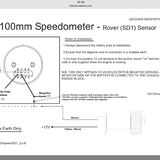
LT77 speedo sensor
Discussion


you do need to drop the exhaust but you can do this on your own. I removed rear ARB as well
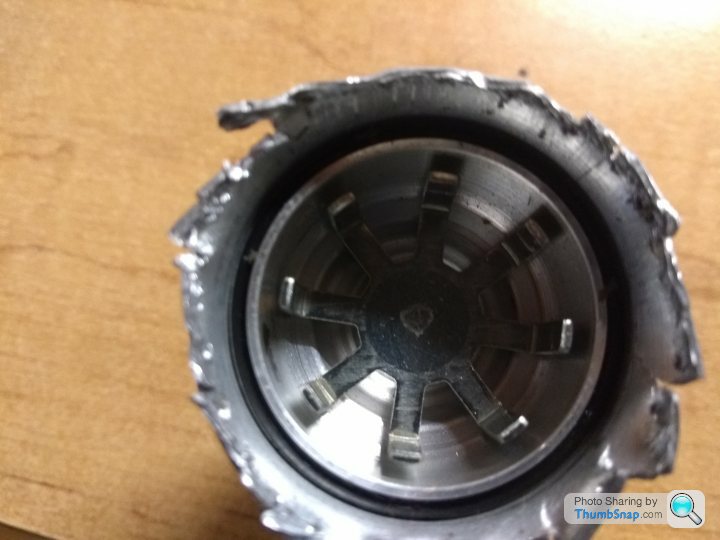
mine speedo was intermittent so i pulled ithe transducer apart, i mean literally, where it is crimped over, open that up and get the pcb out. Replace the wires running through the back and bond it all back up. Bracket holds it all together anyhow one in place.
It's electrically very simple, and unlikely to fail, it is usually connectors and broken wires. i think i posted some pictures a year back.
Ive got a dead one to bits at the moment. Its a pretty simple device with a simple set of metal vanes that run past an inductor. There are a couple of transistors to amplify the signal, but Ive not worked out the full circuit yet. You can still get the transistors, so ill swap these out and see if it works.
blitzracing said:
Ive got a dead one to bits at the moment. Its a pretty simple device with a simple set of metal vanes that run past an inductor. There are a couple of transistors to amplify the signal, but Ive not worked out the full circuit yet. You can still get the transistors, so ill swap these out and see if it works.
Watching with interest.Still need to know how to test one.
Steve
blitzracing said:
Ive got a dead one to bits at the moment. Its a pretty simple device with a simple set of metal vanes that run past an inductor. There are a couple of transistors to amplify the signal, but Ive not worked out the full circuit yet. You can still get the transistors, so ill swap these out and see if it works.
MarkThanks for investigating, I'm also watching with great interest, good to know they are not a simple magnet & reed switch like Land Rover’s & MGR V8's transducers driven off the old style speedo drive cable.
As its signal is switched via transistors could it be powered up by connecting the Yellow Black to 12v and the body to Neg and then test the brown signal wire for 0v and 12v with a multi-meter.
| TVR loom | Speedo Transducer | Function |
| Green | Yellow/Black | +12V Ign |
| Green/Yellow | Brown | Pulse (0v /+12v) |
Also, does anyone know if a black gear with 23 teeth (24.7mm dia) is interchangeable with a Brown gear with 21 teeth (24.6 mm dia), I realise the calibration will change but that’s not an issue for us.
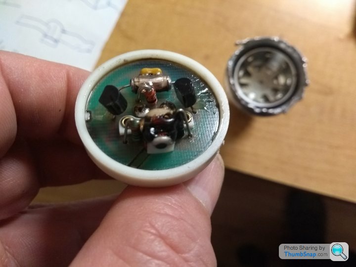
Lucas traditionally use brown for an un switched live and yellow black is the electronic speedo, so the TVR wiring would be around the wrong way? There does not appear to be any way of removing the cog. Anyway heres the guts, there does not appear to be a grounding connection to the case from the electronics.
Now really keen on you finding the fault/cure as it looks like it could be repaired.
Have to say the one I opened will go back much neater than yours. I made a series of cuts into the swagged rim so I could fold back individual 'petals'. If I could replace some components mine would go back together neat enough to offer the repair on customers cars.
Steve
Have to say the one I opened will go back much neater than yours. I made a series of cuts into the swagged rim so I could fold back individual 'petals'. If I could replace some components mine would go back together neat enough to offer the repair on customers cars.
Steve

Mark
Before you start trying to take yours apart any further I have discovered that the wires do no connect through to the PCB as it looks from the PCB side. They connect to a pair of resistors (I think) which then solder into the PCB.
My resistors were broken (or I have broken them) so can you see if you can establish a value before you go any further.
Steve
ETA Look to be 10 Ohm 10% (Brown Black Black Silver)
Edited by Steve_D on Thursday 14th February 14:40
Update. Have made an attempt at the circuit.
If you see a question mark in a part number it means I think there are further markings which I can't read. Mainly because the components are glued to each other.
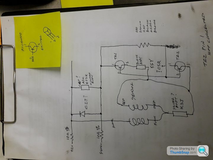
See if it makes any sense. I don't know electronics so am confused at one of the transistors not having pin 1 connected.
Steve
ETA Both transistors are marked C558C PH 5 5
If you see a question mark in a part number it means I think there are further markings which I can't read. Mainly because the components are glued to each other.
See if it makes any sense. I don't know electronics so am confused at one of the transistors not having pin 1 connected.
Steve
ETA Both transistors are marked C558C PH 5 5
Edited by Steve_D on Thursday 14th February 22:34
Im still at a loss with this- firstly there are no resistors in the potting, it is a direct connection to the back of the PCB, but it did look like there was some sort of black sleeve on the back that would look like a broken resistor. I cant see how the coil is wired as there is so much gloop, or what some of the component values are, but all the semiconductors on mine appear to be in order, so not much else to blow really. The lack of a ground confuses me, and why you have a transistor with just the base and collector connected is really weird. I can see that the twin coils will use the metal to change the coils inductance as it passes, but that needs some sort of oscillator to pick up the change. Ill rewire just the PCB and and scope it to see if there are any ac wave forms.
ummm- i did a resistance check before I pulled it to bits and it gave 0 ohms between the wires and the PCB. I got it to bits with some heat, so did not need a Dremmel. Im still none the wiser on how it works, especially with the two wire transistor.... I can confirm I think it needs a ground path to get a reading via the speedo sensor wire, although a colleague managed to get a reading of sorts on ohms on a DVM. I did get a nice square wave with a scope and it connected to a speedo, but I dont have a speedo to hand now to repeat the experiment.
Edited by blitzracing on Wednesday 20th February 09:14
Steve_D said:
Sorry for poor pic. trying to use my phone.
Enough of the resistor body to read the value

In this you can see the ball ends of the leads that go into the carbon
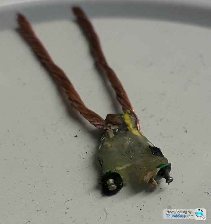
Steve
Id say looking at the remains you have a 10 ohm resistor on one side and a diode on the other. The diode will stop any damage if the voltages are reversed. The resistor could just be there to limit the current if the output wire was grounded directly by mistake.Enough of the resistor body to read the value
In this you can see the ball ends of the leads that go into the carbon
Steve
Edited by Steve_D on Monday 18th February 13:03
Better picture showing the remnants of the wire wound resistor which is why I think they are both resistors.
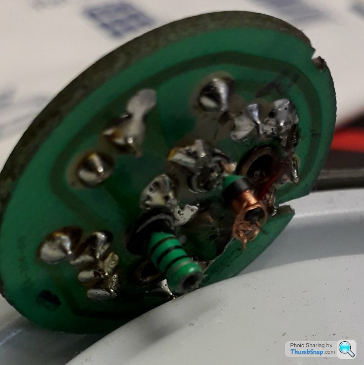
You mentioned the gloop preventing you seeing where the pickup wires terminated. same on mine but i'm pretty sure i've identified mine and have them correct on my cct diag.
Steve
You mentioned the gloop preventing you seeing where the pickup wires terminated. same on mine but i'm pretty sure i've identified mine and have them correct on my cct diag.
Steve
blitzracing said:
Im still at a loss with this- firstly there are no resistors in the potting, it is a direct connection to the back of the PCB, but it did look like there was some sort of black sleeve on the back that would look like a broken resistor. I cant see how the coil is wired as there is so much gloop, or what some of the component values are, but all the semiconductors on mine appear to be in order, so not much else to blow really. The lack of a ground confuses me, and why you have a transistor with just the base and collector connected is really weird. I can see that the twin coils will use the metal to change the coils inductance as it passes, but that needs some sort of oscillator to pick up the change. Ill rewire just the PCB and and scope it to see if there are any ac wave forms.
Blitz, the transistors are PNP, so current flow is emitter to collector and base - TR2 is shown as open collector. It looks like a simple LC oscillator tank circuit to me, with TR2 acting as a simple PN junction diode at the bottom of the LC part. TR1 and its circuit does the 'squaring'. Also the unit's 'earth' is realised via the Brown line and an external pull down resistor. Gassing Station | Griffith | Top of Page | What's New | My Stuff