Instructions to change fuel maps on 14CUX Griffith, Chimaera
Discussion


I know that other Lucas ECU used in Nissan Primera 2.0 SLX P10 93 possible to modify for using O2 sensors based on zirconium. Only needed to cut that resistor making 0.45V like basic for titanium O2 sensor. I am going to try it. In general it sounds good. ADC converter in the end operating by voltage 0-1V so same what we get from zirconium sensor.
I think you would need to get up to around 1.2 volts minimum to have any real effect on the shunting- right at the point the response curve flattens right off. Personally I think a better bet would just be turn the lambda feedback off completely from say 1500 to 2000 rpm, and just tweak the map if needed in that region. I don't think my worries about cooking the catalyst would be an issue any more as you can chuck 13.5:1 AFR into the cats at WOT and they don't melt, and this is where you want to be to reduce the shunting. As for the potential divider- don't forget the voltage source for the resistive probe voltage is the 12 volt heater wire, so this will fluctuate with the battery voltage, and influence the output, so maybe this just reduces the effect against using a stabilised voltage?
Edited by blitzracing on Thursday 14th September 20:28
MPO said:
I want to extend my cranking time before the injectors start pulsing any idea where this variable is in the code anyone?
Cheers
MPO
Maybe try "startupDelayCount" in the data asm file, you probably missed it becuase its not in the normal data section (0->800) but rather a constant in the code.Cheers
MPO
Please let me know if it works.
Steve
Hi, to all first time poster. This is not strictly a tvr issue, but relating to tunerpro and the 14cux adx file.
My hard drive died recently ,and after a new hard drive and new install of win7 (64bit), I am having a problem getting tunerpro to work properly.
After I load the xdf file there are maps and scalars listed on the tree, but only about half of them. Flags are missing altogether.
I have tried various versions of tunerpro, and I have uploaded all the microsoft c++ visual studio things I can find. ,but still no good.
Has anyone here had cause to reload tunerpro recently. Any advice appreciated. Steve ( range rover classic 4.6 Thor manifold)

RR90 said:
Hi, to all first time poster. This is not strictly a tvr issue, but relating to tunerpro and the 14cux adx file.
My hard drive died recently ,and after a new hard drive and new install of win7 (64bit), I am having a problem getting tunerpro to work properly.
After I load the xdf file there are maps and scalars listed on the tree, but only about half of them. Flags are missing altogether.
I have tried various versions of tunerpro, and I have uploaded all the microsoft c++ visual studio things I can find. ,but still no good.
Has anyone here had cause to reload tunerpro recently. Any advice appreciated. Steve ( range rover classic 4.6 Thor manifold)
Yes and I reinstalled an old version.My hard drive died recently ,and after a new hard drive and new install of win7 (64bit), I am having a problem getting tunerpro to work properly.
After I load the xdf file there are maps and scalars listed on the tree, but only about half of them. Flags are missing altogether.
I have tried various versions of tunerpro, and I have uploaded all the microsoft c++ visual studio things I can find. ,but still no good.
Has anyone here had cause to reload tunerpro recently. Any advice appreciated. Steve ( range rover classic 4.6 Thor manifold)
As you are running Windows 7 I suggest you also stick to the older version, below, which also contains the required Visual C++ runtime.
http://www.remap-14cux.uk/TunerPro/TunerProWin7(VC...
Here are my latest 14CUX Definition files and checksum.dll that needs to be copied to the TunerPro directory.
http://www.remap-14cux.uk/TunerPro/TunerPro14CUXCo...
However, if you’ve updated your Visual C++ runtime and can’t down grade VC to the earlier 2013 you could try this later TunerPro 5.
Free Version
http://www.remap-14cux.uk/TunerPro/vc2015/SetupTun...
Emulator Version
http://www.remap-14cux.uk/TunerPro/vc2015/SetupTun...
Visual C++ 2015 Runtime
http://www.remap-14cux.uk/TunerPro/vc2015/vc_redis...
http://www.remap-14cux.uk/TunerPro/vc2015/vc_redis...
Please let me know how you get on.
Steve
Your files worked a treat. I tried them on my desktop pc initially, without luck. My pc then croaked it and refused to boot up.
I then tried my rovergauge laptop and it worked first go. I'm guessing my desktop is haunted.
Anyway ,I'm back in business, your help was much appreciated . Thanks again Steve.
I then tried my rovergauge laptop and it worked first go. I'm guessing my desktop is haunted.
Anyway ,I'm back in business, your help was much appreciated . Thanks again Steve.
Now that my laptop is working ,I am trying to remap my 4.6 with the 5am afm
I am happy enough with the afm scalar ,(91) but now the block used at idle is hard up against the top row.
Am I right in thinking the row scalar adjustment will shift it down one row if I increase this value?
Thanks,Steve
I am happy enough with the afm scalar ,(91) but now the block used at idle is hard up against the top row.
Am I right in thinking the row scalar adjustment will shift it down one row if I increase this value?
Thanks,Steve
How have you set the afm scalar ? the scalar and offset need to be massaged a bit at a time to get the ecu using the complete map from overrun to full throttle. Unless you've looked at the usage of the map at full throttle, and on overrun, you won't know if your values are right. The Lucas map is small so using the available rows wisely is an important first step. If your engine is near standard, using standard values is probably the best advice especially if you're testing things out on the road rather than a dyno or datalogging.
I have tried to set the scalar by driving at full throttle up a local hill, while rovergauge is being recorded by video camera in the back seat. It's a bit crude but I have got as close as I can, I have also bumped the main scalar up a bit.
I think I'm in the ballpark, but I want to move the idle down one row.
I think I'm in the ballpark, but I want to move the idle down one row.
I have to add, my car is a 90 range rover classic.
The block is 4.6, with crower 50229 cam and Thor manifold. So the fuel map is gong to be a bit weird. The ignition map certainly is. (Megajolt). It tends to not like too much advance under load at around 2000 rpm, most maps seem to have around 18-20 degrees, I have about 10-12 at the moment.
In hindsight maybe a less torquey type cam would have been a better choice, and let the manifold take care of the low speed area.
I may retard the cam a couple of degrees if I have the need to take the timing cover off.
Cheers Steve
RR90 said:
I have to add, my car is a 90 range rover classic.
The block is 4.6, with crower 50229 cam and Thor manifold. So the fuel map is gong to be a bit weird. The ignition map certainly is. (Megajolt). It tends to not like too much advance under load at around 2000 rpm, most maps seem to have around 18-20 degrees, I have about 10-12 at the moment.
In hindsight maybe a less torquey type cam would have been a better choice, and let the manifold take care of the low speed area.
I may retard the cam a couple of degrees if I have the need to take the timing cover off.
Cheers Steve
Hi, I have the same setup. 14cux and megajolt.The block is 4.6, with crower 50229 cam and Thor manifold. So the fuel map is gong to be a bit weird. The ignition map certainly is. (Megajolt). It tends to not like too much advance under load at around 2000 rpm, most maps seem to have around 18-20 degrees, I have about 10-12 at the moment.
In hindsight maybe a less torquey type cam would have been a better choice, and let the manifold take care of the low speed area.
I may retard the cam a couple of degrees if I have the need to take the timing cover off.
Cheers Steve
When I rev the motor up to 5500-6000 rpm most times the ecu freezes and engine dies. I need to switch of ignition for a few sec (until the relay clicks) and then restart. Do you experience any issue like this?
In the connection between coil signals and 14cux rpm pickup, what are you using? zener diode? resistor?
The 14CUX is pretty bullet proof, Ive never seen it glitch due to external EMF or stray signals from an ignition source, so if the ECU is locking up, Id assume the processor is hanging. A simple thing to try is fit resistive plugs as this calms down stray EMF from the coils as they switch, should that be glitching the 14CUX. Can you get reliable RPM readings on the 14CUX from the Megajolt with RoverGauge? Otherwise Id use 4 simple diodes to feed the ECU input- something like a IN4007 as the back EMF from the coils can be hundreds of volts. The negative side of the diodes would go to the negative side of the coils, and the positive side of the diodes would all be joined together and connected to the ECU input. You will also need a pull up resistor (say 1k ohms) to the ignition from ECU input to hold it at 12 volts when the coils are not grounded by the megajolt switching signal.
Edited by blitzracing on Friday 28th December 09:55
blitzracing said:
The 14CUX is pretty bullet proof, Ive never seen it glitch due to external EMF or stray signals from an ignition source, so if the ECU is locking up, Id assume the processor is hanging. A simple thing to try is fit resistive plugs as this calms down stray EMF from the coils as they switch, should that be glitching the 14CUX. Can you get reliable RPM readings on the 14CUX from the Megajolt with RoverGauge?
Resitive plugs I have not tried. The RPM readings are stable and reliable.
blitzracing said:
Otherwise Id use 4 simple diodes to feed the ECU input- something like a IN4007 as the back EMF from the coils can be hundreds of volts.
I am using bellow schematic (with 4 diodes) and 15v zener diode. I have tried both with the 6.8K resistor or without.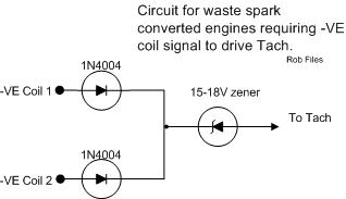
blitzracing said:
The negative side of the diodes would go to the negative side of the coils, and the positive side of the diodes would all be joined together and connected to the ECU input.
If I understand your message, my diodes are correct.blitzracing said:
You will also need a pull up resistor (say 1k ohms) to the ignition from ECU input to hold it at 12 volts when the coils are not grounded by the megajolt switching signal.
I have not installed a pull -up resistor. I will give it a try.The way you have the diagram- the diodes would be putting 12 volts onto the tacho input as the megajolt turns the coils on (leading edge) and you would need a resistor to ground, not 12v that way around to make sure the tacho input drops cleanly to 0 volts as the coils goes off. I think Its more usual to trigger on a 12v to 0 volt signal, (trailing edge) as the wave forms on the primary of the coil are very different as the voltages collapse in the coil primary and produces a couple of extra voltage spikes. The tacho triggers off the biggest spike that can be 100's of volts. Its also why there is a 6.8 k reistor there to stop these spikes reaching the ECU. You could try the diodes around the other way with a pull up resistor
Have a look here:
https://www.picoauto.com/library/automotive-guided...
My other concern would be the "mark-space" ratio of the signal you are using. The coils have a long dwell period as you have 4 of them, with a relatively short firing time and as it now if there is power on any coil, then the tacho input is high, so according to the diagram you would only get a low voltage to the tach when all 4 coils are at 0 volts, and I have no idea how long or when this occurs on your system. Personally Id be happier with the tacho input dropping to zero when any coil drops to zero with the diodes around the other way (??). Of course we could simply be getting confused over it all if you have stable tacho readings anyway.

Hi - hopefully just a quick question as a newbie. I have a 1992 RRC 3.9l V8 with no cat and a 14CUX. Following your super instructions I managed to hook it up to my laptop with RoverGuage and a FTDI board from my local electronics store. I then got a bit carried away cutting out the old EPROM with the dremel (as it was running fine on a 2666 tune) and soldered in a socket and a mate has written me a 3383 tune with 2 fuel maps that was online and it all works sweetly. As I am just having a play - I have just got another 3383 tune out of a junked 1994? Disco thanks to my handy new cable and Roverguage. It has all 5 fuel maps on it. But actual question was - is the 3383 about as good as gets for a stock tune for a 1992 RRC 3.9l V8 with no cat and a 14CUX?
Gassing Station | Griffith | Top of Page | What's New | My Stuff